
INTRODUCING A UML PROFILE FOR
DISTRIBUTED SYSTEM CONFIGURATION
1,2
N. Alexopoulou,
1
A. Tsadimas,
1
M. Nikolaidou,
1,2
A. Dais,
1
D. Anagnostopoulos
1
Harokopio University of Athens, El. Venizelou Str 35, 17671, Athens, Greece
2
Department of Informatics and Telecommunications, University of Athens, Panepistimiopolis, 15771, Athens, Greece
Keywords: UML 2.0 extension, UML Profile, Distributed System Configuration, Distributed Application Modelling.
Abstract: Distributed system configuration consists of distributed application component placement and underlying
network design, thus is a complex process dealing with interrelated issues and comprising various stages. A
common metamodel for distributed system representation in all configuration stages is thus required, so that
unclear dependencies between discrete stages can be easily identified. This model should also be easily
adopted by autonomous software tools used for the automation of discrete configuration stages and for the
efficient development of system specifications by designers. We propose such a metamodel using UML 2.0.
More specifically, we introduce a UML 2.0 profile facilitating distributed system configuration process. In
this profile, different UML 2.0 diagrams are integrated and properly extended, in order to model all aspects
of the distributed system configuration process.
1 INTRODUCTION
Distributed system technology provides the platform
to build modern enterprise information systems
consisting of a combination of interrelated Intranet-
based and Internet-based applications. Distributed
systems are built on multi-tiered client-server
models. As they become more complex, there is a
constant effort to provide a common user application
interface through the Web both at Intranet and
Internet level (for example the J2EE architecture).
Such platforms distinguish application logic from
the user-interface and contribute to distributed
system configurability and extensibility. Although,
vendors actively promote information system
development using the aforementioned platforms,
the proposed solutions, although expensive, often
fail to provide the desired performance (Savino-
Vázquez N.N. et al., 2000). A potential cause is that
configuration issues, although interrelated, are
solved in isolation.
In (Nikolaidou et. al, 2005) a systematic
approach for configuring web-based distributed
systems was proposed. A four-staged methodology
was introduced, aiming at the exploration of unclear
dependencies between resource allocation policy
(process and file replica placement and
synchronization) and underlying network
architecture, which are often the source of poor
system performance. The four discrete stages
identified correspond to functional specification,
recourse allocation, network configuration and
performance evaluation. The main advantage of the
proposed methodology is that it allows the adoption
of a common metamodel for the representation of
distributed system architectures in all configuration
stages, ensuring interoperability and model
exchangeability.
Three alternative views are utilized emphasizing
specific requirements of each configuration stage.
Application View is used to describe functional
specifications (e.g. application logic and user
behaviour). Topology View facilitates the definition
of system access points and the resource allocation
and replication. Resources (e.g. processes and data)
and the way they interact are already described
through Application View. Physical View refers to
the aggregate network. Network nodes are either
workstations allocated to users or server stations,
running server processes. Topology and Physical
Views correspond to application and network
architecture respectively, thus they are interrelated.
Both Topology and Physical Views are decomposed
into hierarchical levels of detail. At the lowest level,
network nodes are related to process/data replicas.
In this paper, we focus on the formal definition
of a UML Profile, named Distributed System
Configuration Profile, comprising the UML 2.0
This research was supported in part by Pythagoras program (MIS 89198)
co-funded by the Greek Goverment (25%) and the European Union (75%).
542
Alexopoulou N., Tsadimas A., Nikolaidou M., Dais A. and Anagnostopoulos D. (2006).
INTRODUCING A UML PROFILE FOR DISTRIBUTED SYSTEM CONFIGURATION.
In Proceedings of the Eighth International Conference on Enterprise Information Systems - ISAS, pages 542-545
DOI: 10.5220/0002458405420545
Copyright
c
SciTePress
extensions needed to efficiently model the
aforementioned alterative views of distributed
systems. The profile can be used within Rational
Modeler platform (IBM, 2005). The distributed
system model created by the designer through
Rational Modeler is exported in XML in order to be
used by the proper configuration tool and imported
again in order for the designer to view
corresponding results.
It should be noted that for the representation of
Physical View, UML deployment diagrams are
commonly used to represent network architectures
(Kaehkipuro, 2001). In the proposed model, Physical
View is represented as a deployment diagram. No
additional extension is needed to represent network
architecture. Thus Physical View is not further
discussed. Instead, we focus on application
architecture and functionality representation.
2 APPLICATION VIEW
For each application operating in the distributed
system platform, a discrete Application View is
defined. Applications are conceived as sets of
interacting modules (either server or client), such as
Application Servers, File Server, etc. Each module
offers specific services. Service implementation
consists of simple tasks occurring upon module
activation, called operations. User behaviour is also
described in this View through user profiles
activating client modules. Each profile includes user
requests, which invoke specific services of client
processes operating on the user’s workstation.
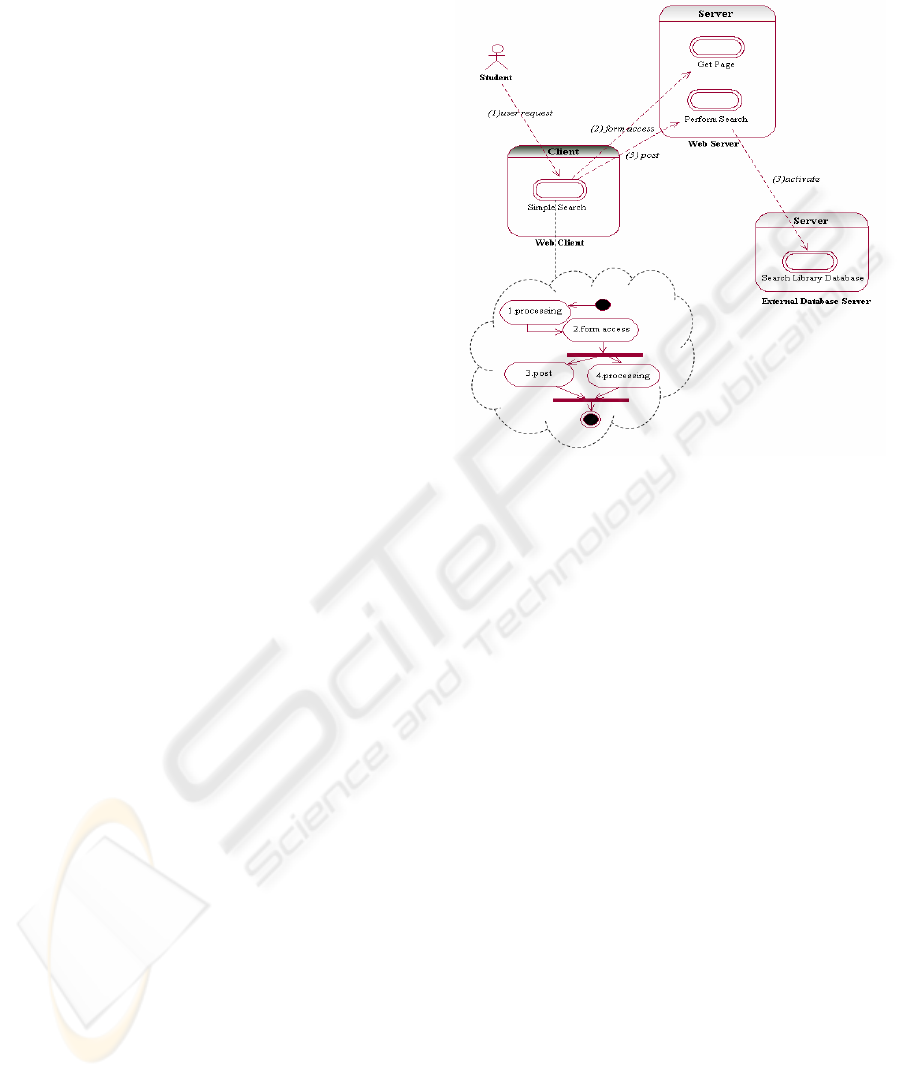
An example of an Application View is presented
in figure 1. A user (student) initiates a simple search
in a library OPAC, thus performs a database search
through the appropriate CGI in the Web Server. In
particular, this example involves three modules,
Web Client, Web Server and External Database
Server depicted through rounded rectangles
respectively labelled. Their services are illustrated
using a double-lined ellipse within each module. The
user profile is represented by the UML actor icon.
Also, as shown in figure 1, interactions among
modules are depicted by dotted arrows between
services. Each service is implemented by a set of
operations, named application operations, selected
from Operation Dictionary. Operations must be
ultimately decomposed into elementary ones (i.e.
processing, storing and transferring) to estimate the
QoS required from the underlying network. Node
elements on the Physical View are responsible for
performing corresponding elementary operations.
Intermediate operations are needed to simplify
operation decomposition. Consequently, Operation
Dictionary comprises three types of operations
(application, intermediate and elementary) in an
interconnected manner showing invocation order
and message passing among them.
As deduced by the previous description,
Application View comprises an external part
showing the interactions among services and hence
among modules, and several internal parts, one for
every service appearing in the external part. The
Simple Search internal part is depicted in figure 1
within the dashed cloud. Each internal part
represents a service implementation, which includes
internal operations as well as operations that require
communication with other modules. For every
operation of the latter there is a corresponding arrow
in the external part labelled with the name of the
operation combined with its sequence number in the
operation flow (e.g. (3)post).
3 TOPOLOGY VIEW
Defining the access points of the system is supported
through Topology View. Topology View comprises
sites, processes and user profiles. The term site is
used to characterize any location (i.e. a building, an
office, etc.). As such, a site is a composite entity
which can be further analyzed into subsites, forming
thus a hierarchical structure. User profiles and
processes are associated with atomic sites, i.e. sites
which cannot be further decomposed, constituting
therefore the lowest level of the hierarchy. In
essence, the hierarchy indicates where (in which
location) each process runs and each user profile is
Figure 1: An example of Application View.
INTRODUCING A UML PROFILE FOR DISTRIBUTED SYSTEM CONFIGURATION
543
placed. The site hierarchy should correspond to the
network architecture depicted in Physical View,
while process and user profiles are related to nodes
included in Physical View.
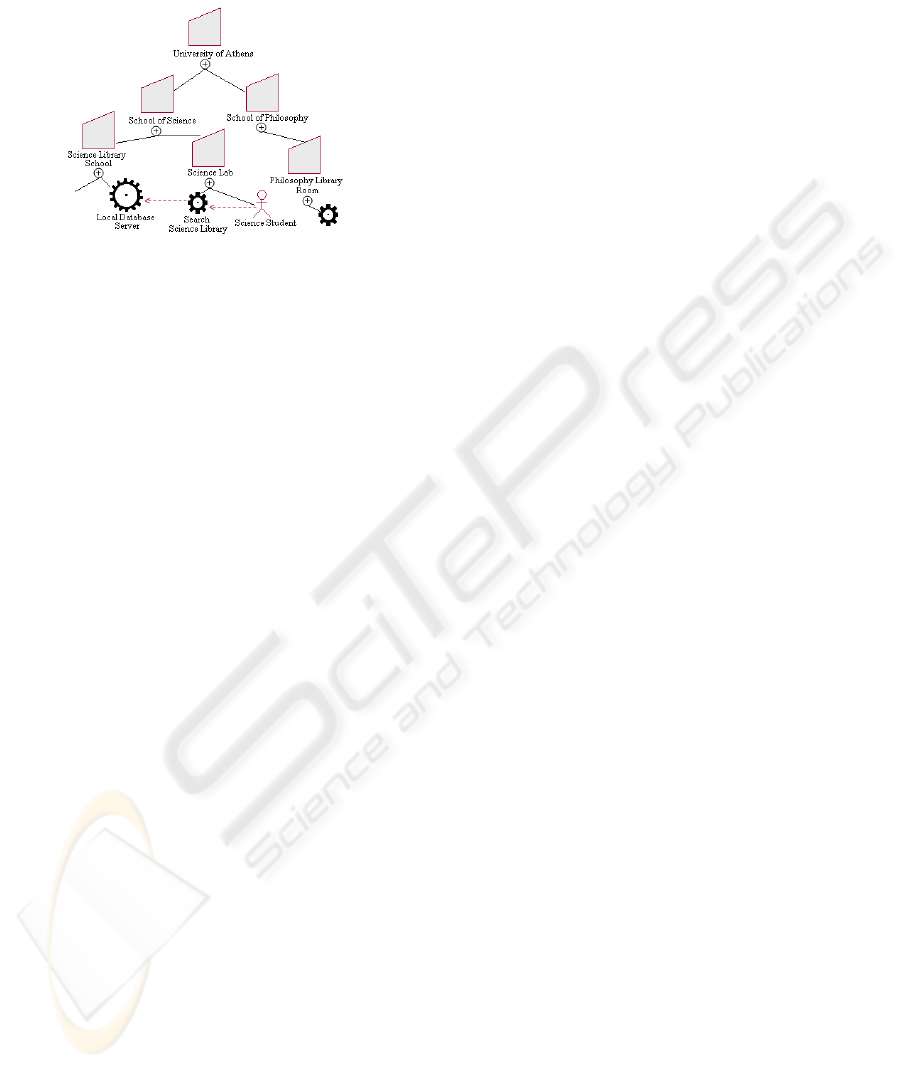
An example of Topology View is shown in figure
2. This example illustrates the University of Athens
and its schools. Sites are depicted through trapezium
icons. According to figure 2, School of Science,
comprises a Science Library and a Science Lab.
Science Lab, for instance, includes the Science
Student Profile and a client process, namely Search
Science Library. The former is illustrated using the
UML actor icon while the latter using the small
cogwheel icon. The large cogwheel denotes a server
process (e.g. Local Database Server). The notation
used for the connections between sites and processes
or user profiles is the membership notation
introduced in UML 2.0. Lastly, figure 2 shows also
the interaction among processes and user profiles
through the dashed lines. These interactions are in
compliance with the interactions among modules
included in the respective Application View, as
processes of Topology View correspond to modules
of Application View.
4 UML EXTENSIONS
All stereotypes that constitute the Distributed
System Configuration Profile are listed in appendix
A, along with the base class they derive from, their
attributes and constraints. As stated implicitly by the
Application View table, the representation of the
external and internal parts of Application View are
based on use cases and activity diagrams
respectively. Use cases in UML are means for
specifying system functionality. As such, they are
suitable for the representation of services, since each
service corresponds to specific functionality offered
by the relative system module. Modelling services as
use cases and the owning modules as packages, we
have used UML in a valid and consistent manner in
order to produce a functional and descriptive model
for our purposes. Indeed, the relation among services
can be pertinently modelled using the Include
relationship defined in UML between use cases.
This relationship means that the base use case is not
complete in itself but dependent on the included use
case (OMG, 2004) similarly as between services in
Application View. Also, the behaviour of a use case
can be described through interaction, activity or state
machine diagrams. We used this feature by adopting
activity diagrams to illustrate the implementation of
a service. Since a service implementation involves
flow of operations, the eligibility of activity
diagrams for its representation is obvious.
As far as Operation Dictionary is concerned,
since it involves interactions between operations
showing in particular invocation order and
parameter passing between them, its representation
is facilitated by the UML communication diagrams
which focus on the interaction between entities.
Lastly, the representation of Topology View is
based on UML component diagrams, because in this
view, system modules are not examined in terms of
their services but they are considered as pieces of
software which must be installed at specific atomic
sites. Furthermore, taking into consideration that
Physical View is modelled by deployment diagrams,
adopting component diagrams for the representation
of Topology View facilitates mapping between the
two views, since the relationship between node and
component model entities are already supported in
the core UML metamodel. As a result, site range can
be mapped onto network range, enabling thus the
identification of dependencies between application
configuration and network topology.
REFERENCES
IBM Co, 2005. Introducing Rational Software Modeler,
http://www-128.ibm.com/developerworks/rational/
library/05/329_kunal/
Kaehkipuro P., 2001. “UML-Based Performance
Modeling Framework for Component-Based
Distributed Systems”, Lecture Notes in Computer
Science 2047, Performance Engineering, Springer-
Verlag.
Nikolaidou M., D. Anagnostopoulos, 2005. “A Systematic
Approach for Configuring Web-Based Information
Systems”, Distributed and Parallel Database Journal,
Vol 17, pp 267-290, Springer Science.
OMG Inc, 2004. UML Superstructure Specification,
Version 2.0, 8/10/2004.
Savino-Vázquez N.N. et al., 2000. “Predicting the
behaviour of three-tiered applications: dealing with
distributed-object technology and databases”,
Performance Evaluation Vol. 39, no 1-4, Elsevier
Press.
Figure 2: An example of Topology View.
ICEIS 2006 - INFORMATION SYSTEMS ANALYSIS AND SPECIFICATION
544

APPENDIX A: Distributed System Configuration Profile.
Stereotype
Base Class Attributes Constraints
ServerModule
Package
Package ServerModulePackages must contain only ServiceUseCases.
ClientModule
Package
Package ClientModulePackages must contain only ServiceUseCases.
ServiceUseCase UseCase
moduleName
inputParameterList
Each ServiceUseCases cannot be related to more than one activity diagram.
The moduleName corresponds to the name of the ServerModulePackage or the ClientModulePackage the
service belongs to.
Invokes Include
A service cannot invoke itself.
Invokes relationship cannot connect UserProfileActors to ServiceUseCases belonging to
ServerModulePackages.
The value of the name attribute of Invokes objects is identical to the value of the name attribute of the
corresponding OperationAction that generated the invocation.
UserProfileAct
or
Actor
activationFrequency
activationProbability
startTime
endTime
The total of the percentage of all initiations starting from a specific UserProfileActor must be 100.
The value of activationFrequency must be either “daily”, “monthly” or “weekly”.
Initiates Association
percentage
valueList
The valueList attribute contains the corresponding values of the inputParameterList of the invoked client
ServiceUseCase.
Initiates relationship may connect only UserProfileActors to ServiceUseCases belonging to a
ClientModulePackage.
Service
Implementation
Activity
Activity
moduleName
inputParameterList
The values of both attributes are identical to the corresponding moduleName and inputParameterList of the
owing ServiceUseCase.
All parameters included in InputParameterList must be passed as values in included OperationAction
valueLists and vs.
OperationActio
n
Action
actionSequence
operation
valueList
targetModule
targetService
The value of operation attribute corresponds to an application operation included in the operation dictionary.
The value of actionSequence must be an “internal” action id.
The value of name is generated by the concatenation of actionSequence and operation.
valueList must comprise the values of the parameters that correspond to the operation attribute. These values
must be either constant or included in the inputParameterList attribute of the corresponding ServiceUseCase.
targetModule must be an existing module defined in the external part of the ApplicationView.
targetService must be one of the ServiceUseCases included in the defined targetModule.
APPLICATION VIEW
ApplicationVie
w
Model
ApplicationView may comprise only ServerModulePackages, ClientModulePackages, ComponentUseCases,
UserPofileActors and relationships of type Invokes or Initiates.
SitePackage Package
range
type
The value of attribute type must be either “atomic” or “composite”.
Composite SitePackages may contain only other SitePackages while simple SitePackages may contain only
ServerProcessComponents, ClientProcessComponents, and UserProfileComponents.
ServerProcess
Component
Component
application
processId
module
application must correspond to one ApplicationView.
The module attribute indicates the corresponding ServerModulePackage in the selected Application View. This
ServerModulePackage must have been already defined.
The value of the name attribute is produced as a concatenation of istanceId and module attributes.
ClientProcess
Component
Component
instances
application
processId
module
application must correspond to one ApplicationView.
The module attribute indicates the corresponding ClientModulePackage in the selected Application View. This
ClientModulePackage must have been already defined.
The value of the name attribute is produced as a concatenation of processId and module attributes.
UserProfile
Component
Component
instances
application
profileId
userProfile
application must correspond to one ApplicationView.
UserProfileComponents may be connected only to ClientProcessComponents.
The value of the name attribute is produced as a concatenation of profileId and userProfile attributes.
The userProfile attribute indicates the corresponding UserProfileActor in the selected Application View. This
UserProfileActor must have been already defined.
Initiate Dependency
Initiate may connect only UserProfileComponents to ClientProcessComponents.
Every Initiate relationship must be included in the corresponding Application View.
Invoke Dependency
Invoke may connect only ClientProcessComponents or ServerProcessComponents to
ServerProcessComponents.
Every Invoke relationship must be included in the corresponding Application View.
TOPOLOGY VIEW
TopologyView Model
TopologyView may comprise only SitePackages, ServerProcessComponents, ClientProcessComponents and
UserProfileComponents.
Elementary
OperationLifeli
ne
Lifeline parameterList
ElementaryOperationLifelines cannot have outcoming arrows (i.e. they do not use other operations).
targetModule and targetService parameters must be included in the parameterList.
Intermediate
OperationLifeli
ne
Lifeline parameterList
Every parameter of each IntermediateOperationLifeline must be passed at least once as input parameter to
another IntermediateOperationLifeline, ElementaryOperationLifeline or ApplicationOperationLifeline.
targetModule and targetService parameters must be included in the parameterList.
Application
OperationLifeli
ne
Lifeline parameterList
Every parameter of each ApplicationOperationLifeline must be passed at least once as input parameter to
another IntermediateOperationLifeline, ElementaryOperationLifeline or ApplicationOperationLifeline.
targetModule and targetService parameters must be included in the parameterList.
Call Message
invocationOrderSet
parameterList
valueList
The union of invocationOrderSets of Call messages sent by each operation must form a sequence starting from
1 while the intersection of invocationOrderSets of Call messages sent by each operation must be equal to ∅.
valuerList must be identical to the parameterList of the invoked operation.
OPERATION DICTIONARY
Operation
Dictionary
Model
OperationDictionary may comprise only ElementaryOperationLifelines, IntermediateOperationLifelines,
ApplicationOperationLifelines and Call relationships between them.
There can only be one OperationDictionary.
All elementary operations must be included in advance in the OperationDictionary.
INTRODUCING A UML PROFILE FOR DISTRIBUTED SYSTEM CONFIGURATION
545
