
Thermal Model of a House using Electric Circuits Analogy
Xhilda Merkaj
1 a
, Darjon Dhamo
2 b
and Eglantina Kalluc¸i
1
1
Applied Mathematics Department, Faculty of Natural Sciences, University of Tirana, Tirana, Albania
2
Automation Department, Faculty of Electrical Engineering, Polytechnic University of Tirana, Tirana, Albania
Keywords:
Smart Grid, Green Communications, Energy Efficiency, Energy Aware.
Abstract:
The aim of this paper is to produce a thermal model of a house using electrical circuit analogy which gives
information about indoor temperatures and power consumption of electrical heater in each room of the house.
The information obtained from the power consumption of each electrical heater serves to estimate the peak
consumption which gives problems in the grid. The house under survey has 5 rooms: a bedroom, a bathroom,
a kitchen, a living-room, and an anteroom. The layers of internal and external walls, windows, roofs and
floors are thermal modeling into electrical components from which a circuit is assembled. Using node voltage
method in each circuit a state space equations are obtained, each of this equations are simulated in MATLAB
environment considering electrical heater time of use based on occupant behavior. Having this model allows
us to simulate the change of temperature of each room, design efficiency the controls algorithm and estimates
peak consumption for improving its reduction.
1 INTRODUCTION
A recent report from the International Energy Agency
(IEA, 2018) shows that energy consumption has in-
creased, especially in the residential and commer-
cial buildings sector. Excessive energy consumption
nowadays has caused problems for the environment
due to the increase in carbon emissions and there-
fore the reduction of energy consumption especially
in buildings is a trend in the world today. Statistics
(ERE, 2017) show that in Albania only 49 of total en-
ergy goes to residential users. Seeing these problems
we decided that the main contribution in this paper is
to use analogies between thermal and electrical mod-
els and methods in order to obtain a better durabil-
ity in terms of increasing energy efficiency in build-
ings. This analogy is the most important objective
for smart grid technologies. Reduction of energy con-
sumption can be done by choosing materials that are
good thermal insulators or with efficient management
of heating or cooling. An energy efficient building has
many advantages including reduction of the green-
house effect, environment degradation, consumption
of natural resources, energy dependence on the out-
side and environmental damage and pollution. It de-
crease costs in energy from houses and businesses, in-
a
https://orcid.org/0000-0002-8084-2907
b
https://orcid.org/0000-0003-0058-6550
crease the security of the energy supply and decrease
production costs.In this article the thermal model of
a house is created using electric circuit analogy (Par-
nis, 2012),(Vasak et al., 2011), (Ivan et al., 2017). The
house is composed of 5 rooms where each of them has
an RC circuit model where R and C represent respec-
tively the resistance and thermal capacity of the ma-
terial of the layer of walls, ceiling, foundation, win-
dows and doors presented in section 2. The current in
the circuit represents the heat flux and the electric po-
tential at the point represents the temperature of that
point. A model of state space was obtained in each of
the circuits. In section 3 we present the temperatures
and power consumed by the heaters in each room.
The results are obtained by simulating the state space
model in the MATLAB environment (Behravan et al.,
2017)for 168 hours. We are considering outdoor tem-
perature variation for typical winter day in Tirana Al-
bania (Lee et al., 2016). The model in MATLAB also
includes a program that determines the working time
of heaters. Knowing that during working days in Al-
bania normal working time is 08:00-16:00. The total
power consumed by heaters over a week is shown in
section 4 including peak power consumption occur-
rence and its value.
Merkaj, X., Dhamo, D. and Kalluçi, E.
Thermal Model of a House using Electric Circuits Analogy.
DOI: 10.5220/0010401000810088
In Proceedings of the 10th International Conference on Smart Cities and Green ICT Systems (SMARTGREENS 2021), pages 81-88
ISBN: 978-989-758-512-8
Copyright
c
2021 by SCITEPRESS – Science and Technology Publications, Lda. All rights reserved
81

2 THERMAL MODEL OF HOUSE
Consider a storey house (Skruch, 2014) containing
five rooms: a living-room, a bedroom, an anteroom, a
kitchen and a bathroom (Figure 1) (Shi et al., 2018).
The external walls of all rooms are made of four lay-
ers (the total thickness of the walls is 47 cm) includ-
ing mineral wool as an insulating material (15 cm),
internal (1 cm) and external (1 cm) cement-lime plas-
ters, structural clay tile (30 cm). The internal walls
are made of three layers (the thickness of the walls is
12 cm) including brick (10cm) and cement-lime plas-
ter on both sides (1 cm). The roof is flat made of
four layers (24.29 cm thick) including mineral wool
(20 cm), EPDM (ethylene propylene diene monomer)
rubber (4.5 mm), timber wood (2.54 cm) and plaster
ceiling tiles (1.3 cm). The foundation is made of five
layers (61 cm thick) including gravel (15 cm), aer-
ated concrete slab (20 mm), polystyrene as an insulat-
ing material (20 cm), screed (5 cm) and wood (1cm).
All exterior and internal doors are made of wood. All
windows are double glazed.
Living-room
Bedroom
Bathroom
Anteroom Kitchen
Figure 1: Floor plan of the house.
The surfaces of the internal and external walls, floors,
and ceilings A
i j
(m
2
) are summarized in the Table 2.
In the Table 1 is shown list of the rooms. In this table
are considered as rooms the earth and outer space with
index -1 and 0, respectively.
Table 1: List of rooms with associated indexes.
Room name Index i
Earth -1
Outer space 0
Bedroom 1
Bathroom 2
Living-room 3
Kitchen 4
Anteroom 5
Table 2: Areas of the surfaces between separated zones.
A
i j
(m
2
)
-1 0 1 2 3 4 5
1 7.51 21.18 0 6.9 0 0 6.77
2 5.31 10.11 6.9 0 6.9 0 4.8
3 36.43 79.36 0 6.9 0 6.87 4.75
4 13.02 31.07 0 0 6.87 0 11.8
5 9.39 14.14 6.77 4.8 4.75 11.8 0
To obtain the thermal models of each room we will
first start with the dimensions of the foundation, ceil-
ing, walls, windows and doors. Each of them is made
up of several layers of different thicknesses and ma-
terials that influence the room’s interior temperature.
A wall can be represented by an RC electrical circuit
where the active electrical resistance R represents the
thermal resistance of the layer, the capacitance C rep-
resents the thermal capacity of the layer. The same
procedure is performed for foundation, ceiling, door
and window of the room. Knowing the surface, the
thickness and the type of material of each layer, we
first calculate the resistance and thermal capacity of
the layers then obtaining the whole thermal model of
the room based on electrical circuit analogy.
For example, the value of a resistor used to model
the thermal resistance of a layer of area A (m
2
), thick-
ness x (m) and thermal conductivity k (W /mK) is
given by equation 1:
R =
x
A · k
(1)
The electrical capacitance used to model the thermal
capacitance of a wall layer of area A (m
2
), thickness x
(m) and made of material with density ρ (kg/m
3
) and
specific heat c
p
(J/kg · C) is given by equation 2:
C =
x · A · ρ · c
p
3600
(2)
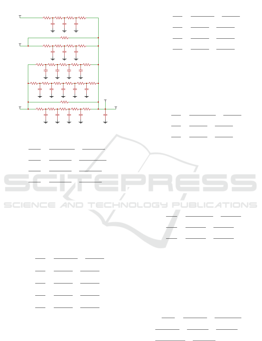
2.1 Bedroom Modeling
The bedroom except the floor, ceiling and walls con-
tain a window which is in contact with the outer space
and a door which is in contact with the anteroom. Af-
ter calculating the resistances and capacities of each
layer we create the whole thermal model of the room
(Bastida et al., 2019). The exterior walls, founda-
tion and ceiling have the same model for each of the
rooms. For this reason, it is not necessary to repeat
these equations many times. The equation are written
in this section.
State Space equations which determine the tem-
perature of each layer of external wall of Bedroom:
SMARTGREENS 2021 - 10th International Conference on Smart Cities and Green ICT Systems
82
C1EWB C2EWB C3EWB C4EWB CRB
R2EWB R3EWB R4EWB R5EWBR1EWB
RW
R1FB R5FBR4FBR3FBR2FB
C4FBC3FBC2FBC1FB
C5FB
R6FB
R1CB R5CBR4CBR3CBR2CB
C4CBC3CBC2CBC1CB
R1IBE R4IBER3IBER2IBE
C3IBEC2IBEC1IBE
RD
C1IBB C2IBB C3IBB
R2IBB R3IBB R4IBBR1IBB
Bedroom
External Wall (EWB)
Window (W)
Foundation (FB)
Ceiling (CB)
Internal Wall Anteroom-Bedroom (IBE)
Internal Wall Bathroom-Bedroom (IBB)
Door (D)
T1EWB T2EWB T3EWB T4EWB
T1FB T2FB T3FB T4FB T5FB
T1CB T2CB T3CB T4CB
T1IBE T2IBE T31IBE
T1IBB T2IBB T3IBB
Toutside
Tanteroom
Tbathroom
Tinside
IheaterBE
Figure 2: Thermal Circuit Model of Bedroom.
C
1ewb
·
dT
1ewb
dt
=
T
outside
−T
1ewb
R
1ewb
+
T
2ewb
−T
1ewb
R
2ewb
C
2ewb
·
dT
2ewb
dt
=
T
1ewb
−T
2ewb
R
2ewb
+
T 3ewb−T2ewb
R3ewb
C
3ewb
·
dT
3ewb
dt
=
T
2ewb
−T
3ewb
R
3ewb
+
T
4ewb
−T
3ewb
R
4ewb
C
4ewb
·
dT
4ewb
dt
=
T
3ewb
−T
4ewb
R
4ewb
+
T
5ewb
−T
4ewb
R
5ewb
(3)
where, C
1ewb
, C
2ewb
, C
3ewb
and C
4ewb
- thermal capac-
ities of each layer of external wall (J/C), T
1ewb
, T
2ewb
,
T
3ewb
, T
4ewb
and T
5ewb
- Temperature of each layer of
external wall (C), T
outside
, - outside temperature (C),
R
1ewb
, R
2ewb
, R
3ewb
, R
4ewb
and R
5ewb
- thermal resis-
tance of each layer of external wall (C/W).
State Space equations which determine the tem-
perature of each layer of foundation of Bedroom:
C
1 f b
·
dT
1 f b
dt
=
T
outside
−T
1 f b
R
1 f b
+
T
2 f b
−T
1 f b
R
2 f b
C
2 f b
·
dT
2 f b
dt
=
T
1 f b
−T
2 f b
R
2 f b
+
T
3 f b
−T
2 f b
R
3 f b
C
3 f b
·
dT
3 f b
dt
=
T
3 f b
−T
2 f b
R
3 f b
+
T
4 f b
−T
3 f b
R
4 f b
C
4 f b
·
dT
4 f b
dt
=
T
3 f b
−T
4 f b
R
4 f b
+
T
5 f b
−T
4 f b
R
5 f b
C
5 f b
·
dT
5 f b
dt
=
T
4 f b
−T
5 f b
R
5 f b
+
T
6 f b
−T
5 f b
R
6 f b
(4)
where, C
1 f b
, C
2 f b
, C
3 f b
, C
4 f b
and C
5 f b
- thermal ca-
pacities of each layer of foundation (J/C), T
1 f b
, T
2 f b
,
T
3 f b
, T
4 f b
, T
5 f b
and T
6 f b
, - temperature of each layer
of foundation (C), R
1 f b
, R
2 f b
, R
3 f b
, R
4 f b
, R
5 f b
and
R
6 f b
- thermal resistance of each layer of foundation
(C/W).
State Space equations which determine the tem-
perature of each layer of ceiling of Bedroom:
C
1cb
·
dT
1cb
dt
=
T
outside
−T
1cb
R
1cb
+
T
2cb
−T
1cb
R
2cb
C
2cb
·
dT
2cb
dt
=
T
1cb
−T
2cb
R
2cb
+
T
3cb
−T
2cb
R
3cb
C
3cb
·
dT
3cb
dt
=
T
2cb
−T
3cb
R
3cb
+
T
4cb
−T
3cb
R
4cb
C
4cb
·
dT
4cb
dt
=
T
3cb
−T
4cb
R
4cb
+
T
5cb
−T
4cb
R
5cb
(5)
where, C
1cb
, C
2cb
, C
3cb
and C
4cb
- thermal capacities
of each layer of ceiling (J/C), T
1cb
, T
2cb
, T
3cb
, T
4cb
and T
5cb
- Temperature of each layer of external ceil-
ing (C), R
1cb
, R
2cb
, R
3cb
, R
4cb
and R
5cb
- thermal re-
sistance of each layer of external ceiling (C/W ).
State Space equations which determine the tem-
perature of each layer of internal wall between ante-
room and bedroom:
C
1be
·
dT
1be
dt
=
T
anteroom
−T
1be
R
1be
+
T
2be
−T
1be
R
2be
C
2be
·
dT
2be
dt
=
T
1be
−T
2be
R
2be
+
T
3be
−T
2be
R
3be
C
3be
·
dT
3be
dt
=
T
2be
−T
3be
R
3be
+
T
4be
−T
3be
R
4be
(6)
where, C
1be
, C
2be
and C
3be
- thermal capacities of each
layer of internal wall between anteroom and bedroom
(J/C), T
1be
, T
2be
, T
3be
and T
4be
- temperature of each
layer of internal wall between anteroom and bedroom
(C), T
anteroom
, - anteroom temperature (C), R
1be
, R
2be
,
R
3be
and R
4be
- thermal resistance of each layer of in-
ternal wall between anteroom and bedroom (C/W ).
State Space equations which determine the tem-
perature of each layer of internal wall between bath-
room and bedroom:
C
1ibb
·
dT
1ibb
dt
=
T
bathroom
−T
1ibb
R
1ibb
+
T
2ibb
−T
1ibb
R
2ibb
C
2ibb
·
dT
2ibb
dt
=
T
1ibb
−T
2ibb
R
2ibb
+
T
3ibb
−T
2ibb
R
3ibb
C
3ibb
·
dT
3ibb
dt
=
T
2ibb
−T
3ibb
R
3ibb
+
T
4ibb
−T
3ibb
R
4ibb
(7)
where, C
1bb
, C
2bb
and C
3bb
- thermal capacities of
each layer of internal wall between bathroom and bed-
room (J/C), T
1bb
, T
2bb
, T
3bb
and T
4bb
- temperature
of each layer of internal wall between bathroom and
bedroom (C),T
bathroom
, - bathroom temperature (C),
R
1bb
, R
2bb
, R
3bb
and R
4bb
- thermal resistance of each
layer of internal wall between bathroom and bedroom
(C/W).
Differential equation which determine the temper-
ature of bedroom:
C
rb
·
d
Tinside
dt
=
T
4ewb
−T
inside
R
5ewb
+
T
outside
−T
inside
R
w
+
T
5 f b
−T
Tinside
R
6 f b
+
T
4cb
−T
inside
R
5cb
+
T
3be
−T
inside
R
4be
+
T
anteroom
−T
inside
R
d
+
T
3ibb
−T
inside
R
3ibb
+ I
heatrerBE
(8)
where, C
rb
- thermal capacities of bedroom (J/C),
T
inside
, - bedroom temperature (C), R
w
- thermal re-
sistance of the window of room (C/W ), R
d
- thermal
Thermal Model of a House using Electric Circuits Analogy
83

resistance of the door of room (C/W ), I
heatrerBE
- heat
flux of heater in bedroom.
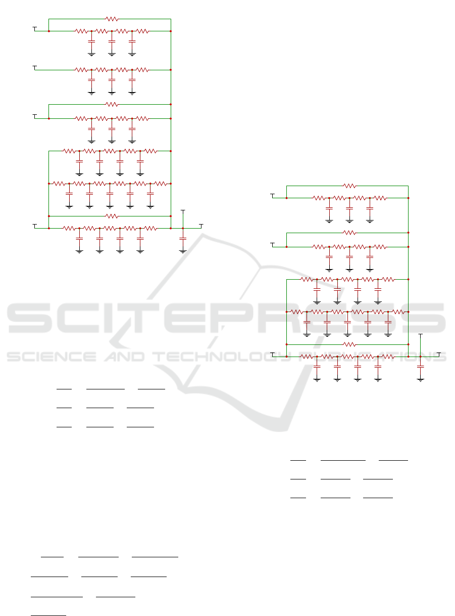
2.2 Bathroom Modeling
The bathroom except the floor, ceiling and walls con-
tain a window which is in contact with the outer space
and a door which is in contact with the anteroom. Af-
ter calculating the resistances and capacities of each
layer we create the whole thermal model of the room.
R1IBB R4IBBR3IBBR2IBB
C3IBBC2IBBC1IBB
RD
C1IB C2IB C3IB
R2IB R3IB R4IBR1IB
C1C C2C C3C C4C
R2C R3C R4C R5CR1C
R6F
C5F
C1F C2F C3F C4F
R2F R3F R4F R5FR1F
RW
R1EW R5EWR4EWR3EWR2EW
CRC4EWC3EWC2EWC1EW
C1ILB C2ILB C3ILB
R2ILB R3ILB R4ILBR1ILB
Internal Wall Bedroom-Bathroom (IBB)
Internal Wall Anteroom-Bathroom(IB)
Ceiling (C)
Foundation (F)
Window (W)
External Wall (EW)
Internal Wall Living-Bedroom (ILB)
Door (D)
Bathroom
T1EW T2EW T3EW T4EW
T1F T2F T3F T4F T5F
T1C T2C T3C T4C
T1IBB T2IBB T3IBB
T1IB T2IB T3IB
T1ILB T2ILB T3ILB
Tinside
Tbathroom
Tanteroom
Toutside
TLiving-room
IheaterB
Figure 3: Thermal Circuit Model of Bathroom.
State Space equations which determine the tempera-
ture of each layer of internal wall between anteroom
and bathroom:
C
1ib
·
dT
1ib
dt
=
T
anteroom
−T
1ib
R
1ib
+
T
2ib
−T
1ib
R
2ib
C
2ib
·
dT
2ib
dt
=
T
1ib
−T
2ib
R
2ib
+
T
3ib
−T
2ib
R
3ib
C
3ib
·
dT
3ib
dt
=
T
2ib
−T
3ib
R
3ib
+
T
4ib
−T
3ib
R
4ib
(9)
where, C
1ib
, C
2ib
and C
3ib
- thermal capacities of each
layer of internal wall between anteroom and bath-
room (J/C), T
1ib
, T
2ib
, T
3ib
and T
4ib
- temperature
of each layer of internal wall between anteroom and
bathroom (C), Tanteroom, - anteroom temperature (C)
R
1ib
, R
2ib
, R
3ib
and R
4ib
- thermal resistance of each
layer of internal wall between anteroom and bathroom
(C/W)
State Space equations which determine the tem-
perature of each layer of internal wall between bed-
room and bathroom are the same as (7).
System of differential equations which determine
the temperature of each layer of internal wall between
bathroom and living-room:
C
1ilb
·
dT
1ilb
dt
=
T
Living
−T
1ilb
R
1ilb
+
T
2ilb
−T
1ilb
R
2ilb
C
2ilb
·
dT
2ilb
dt
=
T
1ilb
−T
2ilb
R
2ilb
+
T
3ilb
−T
2ilb
R
3ilb
C
3ilb
·
dT
3ilb
dt
=
T
2ilb
−T
3ilb
R
3ilb
+
T
4ilb
−T
3ilb
R
4ilb
(10)
where, C
1lb
, C
2lb
and C
3lb
- thermal capacities of each
layer of internal wall between living-room and bath-
room (J/C), T
1lb
, T
2lb
, T
3lb
and T
4lb
- temperature of
each layer of internal wall between living-room and
bathroom (C), TLiving-room, - Living-room temper-
ature (C) R
1lb
, R
2lb
, R
3lb
and R
4lb
- thermal resistance
of each layer of internal wall between anteroom and
bathroom (C/W)
Differential equations which determine the tem-
perature of bedroom:
C
r
·
dT
inside
dt
=
T
4ew
−T
inside
R5ew
+
T
outside
−Tinsde
R
w
+
T
5 f
−T
inside
R
6 f
+
T
4c
−T
inside
R
5c
+
T
5ib
−Tinsde
R
4ib
+
T
anteroom
−T
inside
R
d
+
T
3ibb
−T
inside
R
4ibb
+
T 3ilb−Tinsde
R4ilb
+ I
heatrerB
(11)
where, C
r
- thermal capacities of bathroom (J/C),
T
inside
, - bathroom temperature (C), R
w
- thermal resis-
tance of the window (C/W), R
d
- thermal resistance of
the door (C/W), I
heatrerB
- heat flux of heater in bath-
room.
2.3 Living-room Modeling
The Living-room except the floor, ceiling and walls
contain four windows which are in contact with the
outer space and two doors which are in contact re-
spectively with anteroom and kitchen. After calcu-
lating the resistances and capacities of each layer we
create the whole thermal model of the room.
State Space equations which determine the tem-
perature of each layer of internal wall between living-
room and anteroom:
C
1ik
·
dT
1ik
dt
=
T
anteroom
−T
1ik
R
1ik
+
T
2ik
−T
1ik
R
2ik
C
2ik
·
dT
2ik
dt
=
T
1ik
−T
2ik
R
2ik
+
T
3ik
−T
2ik
R
3ik
C
3ik
·
dT
3ik
dt
=
T
2ik
−T
3ik
R
3ik
+
T
4ik
−T
3ik
R
4ik
(12)
where, C
1ik
, C
2ik
and C
3lik
- thermal capacities of each
layer of internal wall between anteroom and living-
room (J/C), T
1ik
, T
2ik
, T
3ik
and T
4ik
- temperature
of each layer of internal wall between anteroom and
living-room (C), T
anteroom
, - anteroom temperature (C)
R
1ik
, R
2ik
, R
3ik
and R
4ik
- thermal resistance of each
SMARTGREENS 2021 - 10th International Conference on Smart Cities and Green ICT Systems
84
R1IL R4ILR3ILR2IL
C3ILC2ILC1IL
C1EWL C2EWL C3EWL C4EWL CRL
R2EWL R3EWL R4EWL R5EWLR1EWL
RW
R1FL R5FLR4FLR3FLR2FL
C4FLC3FLC2FLC1FL
C5FL
R6FL
R1CL R5CLR4CR3CLR2CL
C4CLC3CLC2CLC1CL
R1IK R4IKR3IKR2IK
C3IKC2IKC1IK
RD
C1IBA C2IBA C3IBA
R2IBA R3IBA R4IBAR1IBA
RD1
Door (D)
Internal Wall Kitchen-Living(IL)
External Wall (EWL)
Windows (W)
Foundation (FL)
Ceiling (CL)
Internal Wall Anteroom-Living(IK)
Internal Wall Bathroom-Living (IBA)
Living-room
T1EWL T2EWL T3EWL T4EWL
T1FL T2FL T3FL T4FL T5FL
T1CL T2CL T3CL T4CL
T1IL T2IL T3IL
T1IK T2IK T3IK
T1IBA T2IBA T3IBA
Tkitchen
Toutside
Tanteroom
Tbathroom
Tinside
IheaterL
Figure 4: Thermal Circuit Model of Living-room.
layer of internal wall between anteroom and living-
room (C/W).
State Space equations which determine the tem-
perature of each layer of internal wall between living-
room and bathroom are the same as (10).
State Space equations which determine the tempera-
ture of each layer of internal wall between kitchen and
living-room:
C
1il
·
dT
1il
dt
=
T
kitchen
−T
1il
R
1il
+
T
2il
−T
1il
R
2il
C
2il
·
dT
2il
dt
=
T
1il
−T
2il
R
2il
+
T
3il
−T
2il
R
3il
C
3il
·
dT
3il
dt
=
T
2il
−T
3il
R
3il
+
T
4il
−T
3il
R
4il
(13)
where, C
1il
, C
2il
and C
3lil
- thermal capacities of
each layer of internal wall between living-room and
kitchen (J/C), T
1il
, T
2il
, T
3il
and T
4il
- temperature of
each layer of internal wall between living-room and
kitchen (C), T
kitchen
, - kitchen temperature (C) R
1il
,
R
2il
, R
3il
and R
4il
- thermal resistance of each layer of
internal wall between living-room and kitchen (C/W )
Differential equations which determine the tem-
perature of living-room:
C
rl
·
dT
inside
dt
=
T
4ewl
−T
inside
R
5ewl
+
T
outside
−T
inside
R
w
+
T
5 f l
−T
inside
R
6 f l
+
T
4cl
−T
inside
R
5cl
+
T
3ik
−T
inside
R
4ik
+
T
anteroom
−T
inside
R
d
+
T
3iba
−T
inside
R
4iba
+
T
3il
−T
inside
R
4il
+ I
heaterL
(14)
where, C
rl
- thermal capacities of living-room (J/C),
T
inside
, - living-room temperature (C), R
w
- thermal
resistance of the window (C/W ), R
d
- thermal resis-
tance of the door (C/W ), I
heatrerL
- heat flux of heater
in living-room.
2.4 Kitchen Modeling
The Kitchen except the floor, ceiling and walls con-
tain two windows which are in contact with the outer
space and two doors which are in contact respectively
with anteroom and living-room. After calculating the
resistances and capacities of each layer we create the
whole thermal model of the room.
R1IL R4ILR3ILR2IL
C3ILC2ILC1IL
RD
C1IA C2IA C3IA
R2IA R3IA R4IAR1IA
C1CK C2CK C3CK C4CK
R2CK R3CK R4CK R5CKR1CK
R6FK
C5FK
C1FK C2FK C3FK C4FK
R2FK R3FK R4FK R5FKR1FK
RW
R1EWK
R5EWKR4EWKR3EW
R2EWK
CRKC4EWKC3EWKC2EWKC1EWK
RD1
Door (D)
Internal Wall Living-Kitchen(IL)
Internal Wall Anteroom-Kitchen(IA)
Ceiling (CK)
Foundation (FK)
Windows (W)
External Wall (EWK)
Kitchen
Door (D1)
T1EWK T2EWK T3EWK T4EWK
T1FK T2FK T3FK T4FK T5FK
T1CK T2CK T3CK T4CK
T1IA T2IA T3IA
T1IL T2IL T3IL
Tinside
TLiving
Tanteroom
Toutside
IheaterK
Figure 5: Thermal Circuit Model of Kitchen.
State Space equations which determine the tempera-
ture of each layer of internal wall between kitchen and
anteroom:
C
1ia
·
dT
1ia
dt
=
T
anteroom
−T
1ia
R
1ia
+
T
2ia
−T
1ia
R
2ia
C
2ia
·
dT
2ia
dt
=
T
1ia
−T
2ia
R
2ia
+
T
3ia
−T
2ia
R
3ia
C
3ia
·
dT
3ia
dt
=
T
2ia
−T
3ia
R
2ia
+
T
4ia
−T
3ia
R
4ia
(15)
where, C
1ia
, C
2ia
and C
3lia
- thermal capacities of each
layer of internal wall between anteroom and kitchen
(J/C), T
1ia
, T
2ia
, T
3ia
and T
4ia
- temperature of each
layer of internal wall between between anteroom and
kitchen (C), T
anteroom
, - anteroom temperature (C)
R
1ia
, R
2ia
, R
3ia
and R
4ia
- thermal resistance of each
layer of internal wall between anteroom and kitchen
(C/W)
State Space equations which determine the tem-
perature of each layer of internal wall between living-
room and kitchen are the same as (13). Differen-
Thermal Model of a House using Electric Circuits Analogy
85
tial equations which determine the temperature of
kitchen:
C
rk
·
dT
inside
dt
=
T
4ewk
−T
inside
R
5ewk
+
T
5 f k
−T
inside
R
6 f k
+
T
4ck
−T
inside
R
5ck
+
T
living
−T
inside
R
d1
+
T
anteroom−
T
inside
Rd
+
T
3il
−T
inside
R
4il
+
T
3ia
−T
inside
R
4ia
+
T
outside
−T
inside
R
w
+ I
heatrerK
(16)
where, C
rk
- thermal capacities of living-room (J/C),
T
inside
, - living-room temperature (C), R
w
- thermal
resistance of the window (C/W ), R
d
- thermal resis-
tance of the door (C/W ), I
heatrerK
- heat flux of heater
in kitchen.
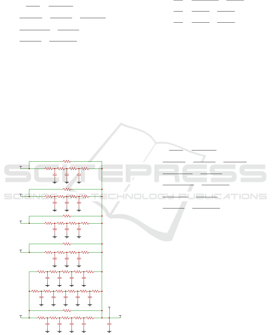
2.5 Anteroom Modeling
The anteroom except the floor, ceiling and walls con-
tain five doors which are in contact respectively with
outer space, bedroom, bathroom, living-room and
kitchen. After calculating the resistances and capaci-
ties of each layer we create the whole thermal model
of the room.
RD3
R1IB R4IBR3IBR2IB
C3IBC2IBC1IB
RD1
C1IBE C2IBE C3IBE
R2IBE R3IBE R4IBER1IBE
C1CA C2CA C3CA C4CA
R2CA R3CA R4CA R5CAR1CA
R6FA
C5FA
C1FA C2FA C3FA C4FA
R2FA R3FA R4FA R5FAR1FA
RD
R1EWA R5EWAR4EWAR3EWAR2EWA
CRAC4EWAC3EWAC2EWAC1EWA
C1IA C2IA C3IA
R2IA R3IA R4IAR1IA
RD2
R1IK R4IKR3IKR2IK
C3IKC2IKC1IK
RD4
Internal Wall Bathroom-Anteroom (IB)
Internal Wall Bedroom-Anteroom(IBE)
Ceiling (CA)
Foundation (FA)
Door (D)
External Wall (EWA)
Internal Wall Kitchen-Anteroom(IA)
Door (D1)
Door (D2)
Internal Wall Living-Anteroom(IK)
Door (D3)
Door (D4)
Anteroom
T1EWA T2EWA T3EWA T4EWA
T1FA T2FA T3FA T4FA T5FA
T1CA T2CA T3CA T4CA
T1IBE T2IBE T3IBE
T1IB T2IB T3IB
T1IA T2IA T3IA
T1IK T2IK T3IK
Tinside
Tbathroom
Tbedroom
Toutside
Tkitchen
TLiving
IheaterA
Figure 6: Thermal Circuit Model of Anteroom.
State Space equations which determine the tempera-
ture of each layer of internal wall between kitchen and
anteroom:
C
1ia
·
dT
1ia
dt
=
T
anteroom
−T
1ia
R
1ia
+
T
2ia
−T
1ia
R
2ia
C
2ia
·
dT
2ia
dt
=
T
1ia
−T
2ia
R
2ia
+
T
3ia
−T
2ia
R
3ia
C
3ia
·
dT
3ia
dt
=
T
2ia
−T
3ia
R
3ia
+
T
4ia
−T
3ia
R
4ia
(17)
where, C
1ia
, C
2ia
and C
3lia
- thermal capacities of each
layer of internal wall between anteroom and kitchen
(J/C), T
1ia
, T
2ia
, T
3ia
and T
4ia
- temperature of each
layer of internal wall between between anteroom and
kitchen (C), T
anteroom
, - anteroom temperature (C)
R
1ia
, R
2ia
, R
3ia
and R
4ia
- thermal resistance of each
layer of internal wall between anteroom and kitchen
(C/W).
System of differential equations which determine
the temperature of each layer of internal wall be-
tween bedroom and anteroom, bathroom and ante-
room, living-room and anteroom, kitchen and ante-
room are respectively the same as (6), (9), (12) and
(15).
Differential equations which determine the tem-
perature of anteroom:
C
ra
·
dT
inside
dt
=
T
4ewa
−T
inside
R
5ewa
+
T
5 f a
−T
inside
R
6 f a
+
T
4ca
−T
inside
R
5ca
+
T
3ibe
−T
inside
R
4ibe
+
T
bedroom
−T
inside
R
d1
+
T
3ib
−T
inside
R
4ib
+
T
bathroom
−T
inside
R
d2
+
T
kitchen
−T
inside
R
d3
+
T
living
−T
inside
R
d4
+
T
3ik
−T
inside
R
4ik
+
T
3ia
−T
inside
R
4ia
+
T
outside
−T
inside
R
d
+ I
heaterA
(18)
where, C
ra
- thermal capacities of anteroom (J/C),
T
inside
, - anteroom temperature (C),(C/W ), R
d
,
R
d1
,R
d2
,R
d3
,R
d4
- thermal resistance of doors (C/W ),
I
heatrerA
- heat flux of heater in anteroom.
3 SIMULATION RESULT
Based on the State Space equations obtained from the
models of thermal circuits of each room we create
models of each room in the Simulink MATLAB en-
vironment. Knowing the dimensions of each layer
given in the first section and the values of the thermal
parameters of each layer Table 4 are calculated the
thermal capacity and resistance of each layer based
on equations (1) and (2).
The model in this environment has been simu-
lated for 168 hours where the outside temperatures
are taken over a week in the city of Tirana, Albania
shown graphically in Figure 7. Knowing that people
in Albania normally work from Monday to Friday
SMARTGREENS 2021 - 10th International Conference on Smart Cities and Green ICT Systems
86
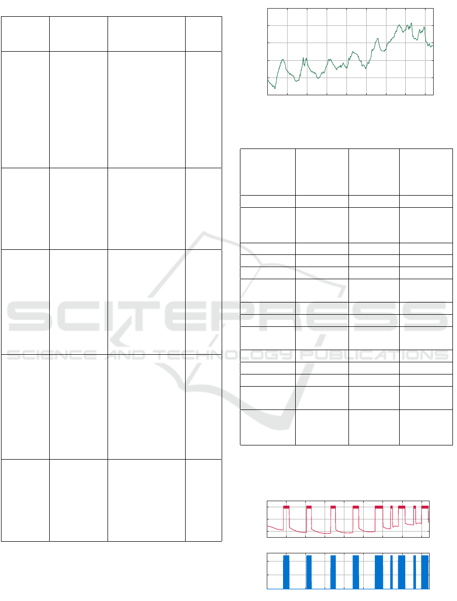
Table 3: Time of use of heater in each room.
Room Day Operating hours Run-
Time
(hours)
Monday 17:00-23:00 6
Tuesday 17:00-22:00 5
Wednesday 18:00-23:00 5
Living
room
Thursday 17:00-23:00 6
Friday 16:00-24:00 8
Saturday 8:00-10:00 2
16:00-23:00 7
Saturday 8:00-10:00 2
16:00-23:00 7
Monday 21:00-23:30 2.5
Tuesday 20:00-23:00 3
Wednesday 22:00-24:00 2
Bedroom Thursday 21:00-23:30 2.5
Friday 21:00-24:00 3
Saturday 20:00-23:00 3
Saturday 21:00-24:00 3
Monday 18:00-21:30 3
Tuesday 17:00-19:00 2
Wednesday 17:30-20:00 2.5
Thursday 18:00-21:00 3
Kitchen Friday 19:00-22:00 3
Saturday 10:00-13:00 3
19:00-21:30 2.5
Saturday 11:00-13:00 2
18:00-21:00 3
Monday 17:00-23:00 6
Tuesday 17:00-22:00 5
Wednesday 18:00-23:00 5
Thursday 17:00-23:00 6
Anteroom Friday 16:00-24:00 8
Saturday 08:00-12:00 4
16:00-23:00 7
Saturday 08:00-13:00 5
16:00-23:00 7
Monday 22:00-23:00 1
Tuesday 21:00-23:00 2
Wednesday 22:00-23:00 1
Bathroom Thursday 21:00-23:00 2
Friday 22:00-23:00 1
Saturday 08:00-09:00 1
Saturday 21:00-23:00 2
between 8:00 and 16:00, we decide the time of oper-
ation of the heaters in each room. The temperature is
controlled with the two-position ON-OFF regulator.
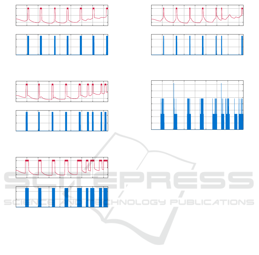
After simulating the thermal model of Living-
room, bedroom, kitchen, anteroom and bathroom
where was implemented also a program which con-
trol the time of use of heater in each room based in
0 20 40 60 80 100 120 140 160
time (hours)
-10
-5
0
5
10
15
Temperature (°C)
Outside temperature
Figure 7: Outside temperature.
Table 4: Time of use of heater.
Material
Descrip-
tion
k c
p
ρ
(W /m · K) (J/kg · C) (W /m · K)
Gravel 0.360 840 1840
Aerated
Concrete
slab
0.160 840 500
Polystyrene 0.030 1380 25
Screed 0.410 840 1200
Wood 0.22 1360 550
Cement
Plaster
0.720 800 1860
Brick 0.840 800 1700
Mosque 0.024
Mineral
Wool
0.046 837 10
Clay Tile 0.840 800 1900
Air 10 1005 1.205
EPDM 0.17 2000 110
Timber
Wood
0.121 837 593
Plaster
Ceiling
Tiles
0.380 840 1120
table 3, the simulation results are obtained and shown
graphically in Figures 8-12.
0 20 40 60 80 100 120 140 160
0
10
20
Temperature (°C)
Living-room temperature
0 20 40 60 80 100 120 140 160
Time (hours)
0
500
1000
Power (W)
Power Consumption of heater
Figure 8: Living-room temperature and power consump-
tion.
Thermal Model of a House using Electric Circuits Analogy
87
0 20 40 60 80 100 120 140 160
0
10
20
Temperature (°C)
Bedroom temperature
0 20 40 60 80 100 120 140 160
Time (hours)
0
500
1000
Power (W)
Power Consumption of heater
Figure 9: Bedroom temperature and power consumption.
0 20 40 60 80 100 120 140 160
0
10
20
Temperature (°C)
Kitchen temperature
0 20 40 60 80 100 120 140 160
Time (hours)
0
500
1000
Power (W)
Power Consumption of heater
Figure 10: Kitchen temperature and power consumption.
0 20 40 60 80 100 120 140 160
0
10
20
Temperature (°C)
Anteroom temperature
0 20 40 60 80 100 120 140 160
Time (hours)
0
500
1000
Power (W)
Power Consumption of heater
Figure 11: Anteroom temperature and power consumption.
4 CONCLUSION
The purposes of this paper has been to develop ther-
mal model of a house using electrical RC circuit anal-
ogy to analyze the temperatures and power consump-
tion of heaters in each room. This analogy makes it
possible to develop directly accurate models insofar
as the temperatures within the walls are not required.
This model is described using state space equations
for temperature response of each room because it is an
efficient and practical method to reduce energy con-
sumption and to improve thermal comfort. We sim-
ulated the model in order to take the temperature of
each room in Matlab, Simulink environment. Dynam-
ics in temperature are controlled using two positional
regulator in specified hours. Total power consump-
tion of all heaters, which is shown in Figure 13 in-
dicates the peak demand occurs between 19:00-20:00
in Tuesday and 08:00- 09:00 in Saturday. Because
0 20 40 60 80 100 120 140 160
0
10
20
Temperature (°C)
Bathroom temperature
0 20 40 60 80 100 120 140 160
Time (hours)
0
500
1000
Power (W)
Power Consumption of heater
Figure 12: Bathroom temperature and power consumption.
0 20 40 60 80 100 120 140 160
time (hours)
0
500
1000
1500
2000
2500
3000
3500
Power (W)
Aggregated House Power
Figure 13: Total power consumption.
of negative effect of peak demand (the cost of energy
production is high due to the use of peaking power
plants) in the future our focus will be reducing energy
for heating using Model Predictive Control (MPC).
REFERENCES
Bastida, H., E.Ugalde-Loo, C., Abeysekera, M., Qadrdan,
M., and Wu, J. (2019). Thermal dynamic modelling
and temperature controller design for a house.
Behravan, A., Obermaisser, R., and Nasari, A. (2017).
Thermal dynamic modeling and simulation of a
heating system for a multi-zone office building
equipped with demand controlled ventilation using
MATLAB/Simulink.
ERE (2017). Raport vjetor, gendja e sektorit t
¨
e energjis
¨
e
dhe veprimtaria e ere-s gjat
¨
e vitit 2016.
IEA (2018). Weo.; iea, world energy outlook.
Ivan, F. S., Buzatu, C., and Popescu, D. (2017). Buildings
thermal modeling.
Lee, T., Asawa, T., Kawai, H., Sato, R., Hirayama, Y., and
Ohta, I. (2016). Multipoint measurement method for
air temperature in outdoor spaces and application to
microclimate and passive cooling studies for a house.
Parnis, G. (2012). Building thermal modelling using elec-
tric circuit simulation.
Shi, H., Liu, J., and Chen, Q. (2018). HVAC precooling
optimization for green buildings: An RC-network ap-
proach.
Skruch, P. (2014). A thermal model of the building for the
design of temperature control algorithms.
Vasak, M., Starcic, A., and Martincevic, A. (2011). Model
predictive control of heating and cooling in a family
house.
SMARTGREENS 2021 - 10th International Conference on Smart Cities and Green ICT Systems
88
