
Real Cockpit Proposal for Flight Simulation with Airbus A32x Models:
An Overview Description
Jos
´
e Carvalho
1 a
, Andr
´
e C. Mendes
1 b
, Thadeu Brito
1,2 c
and Jos
´
e Lima
1,3 d
1
Research Centre in Digitalization and Intelligent Robotics (CeDRI), Instituto Polit
´
ecnico de Braganc¸a,
Campus de Santa Apol
´
onia, 5300-253 Braganc¸a, Portugal
2
Faculty of Engineering of University of Porto, Porto, Portugal
3
INESC TEC - INESC Technology and Science, Porto, Portugal
Keywords:
Flight Simulator, XPlane, Software-in-the-Loop, Hardware-in-the-Loop, Cockpit.
Abstract:
This paper describes the several steps to build an elaborate flight simulator cockpit, where the hardware is de-
signed based on Mechatronic principles and the proposed software was developed using agile methodologies
to create a Cyber-Physical System (CPS). Furthermore, this research attempts to simulate the real environment
from an aircraft as close as possible with a real scale developed cockpit. Based on this, the presented paper
contributions include: (1) The implementation of a complex dynamic system such as a CPS, where the Mecha-
tronic system is part of it; (2) The deployment of a scale model of an Airbus A32x aircraft (one of the most
used), integrating into a mathematical model adapted to the operation of an aircraft flight simulation system,
regarding the physical forces involved. This project is also used to captivate the students’ motivation to the
areas of technology such as electronics and programming and permits its development as a student project and
thesis. Results allow validating the proposed cockpit.
1 INTRODUCTION
Hardware-in-the-Loop (HIL) simulation is a tech-
nique used to develop, test, and validate embedded
systems, by adding the complexity of the plant under
control through a mathematical representation of all
dynamic systems related to the test platform. These
mathematical representations are called “plant simu-
lation” (Gomez, 2001) that communicates with the in-
tegrated system to be tested. This technique reduces
the development cost, time, and risk. These advan-
tages have promoted HIL simulation to become a de-
velopment standard in high-stress industries such as
aeronautics and aerospace. (Ellis, 2012).
On the other hand, Software-in-the-Loop (SIL) is
a tool that allows accurate model validation before
field testing. It is described by the low-cost computer
simulators combined with the reliability of hardware
emulators. Furthermore, it is a solution where model
accuracy and simulation speed do not compete, un-
a
https://orcid.org/0000-0002-6074-8112
b
https://orcid.org/0000-0001-6390-1250
c
https://orcid.org/0000-0002-5962-0517
d
https://orcid.org/0000-0001-7902-1207
like traditional numerical simulators (Demers et al.,
2007).
Nowadays, HIL and SIL simulations are com-
monly used to evaluate controls and algorithms, be-
cause they easily allow dynamic changes in the
model, besides allowing a fast development and in-
creasing safety (Zhang and Mi, 2011; Chudy and
Rzucidlo, 2012). After all, in such specialized in-
dustries (as aeronautics and aerospace), because the
necessity for real test flights is minimized, also re-
ducing the number of peripherals involved and con-
sequently decreasing the project’s final cost (Sampaio
et al., 2013). In the development of a HIL simulator,
first one must implement the real-time “plant simu-
lation”, which is a mathematical representation of all
the dynamics embedded in the plant system. Mod-
ern flight simulation techniques and implementations
often result in many sophisticated and complex cal-
culations that require a high level of computational
power (Gomez, 2001; Gholkar et al., 2004), then the
development of this virtual environment is a difficult
task. The employed simulators in several areas, in-
cluding aeronautics and aerospace, have improved by
the technology development such as powerful proces-
sors, GPU, and I/O interface, among others. Thus,
256
Carvalho, J., Mendes, A., Brito, T. and Lima, J.
Real Cockpit Proposal for Flight Simulation with Airbus A32x Models: An Overview Description.
DOI: 10.5220/0010526002560263
In Proceedings of the 11th International Conference on Simulation and Modeling Methodologies, Technologies and Applications (SIMULTECH 2021), pages 256-263
ISBN: 978-989-758-528-9
Copyright
c
2021 by SCITEPRESS – Science and Technology Publications, Lda. All rights reserved

the idea is to use a realistic commercial flight simu-
lator (COTS-FS) running on a standard PC, compos-
ing a low-cost HIL platform with enough computa-
tional power and storage resources. As a result, the
simulators facilitate training on complex maneuvers
and procedures that cannot be performed safely with
the real aircraft, such as the failure of any of the mo-
tors or other also critical. The simulator increases the
number of practical training hours, accelerates pilots’
training, and notably decreases training costs (Cas-
ner SM, 2013).
There are some add-ons to the flight simulators,
such as TrackIR from NaturalPoint manufacturer that
allows to show the cockpit panels presented on the
monitor depending on the pilot head position, but it
also lacks realism. In this context, the main objec-
tive of this work is to build an elaborate flight simu-
lator system, where the hardware is created based on
Mechatronic policies, that is, focusing on the com-
munication system and the mechanical parts. Indeed,
the purposed software aims to be developed using ag-
ile methodologies to create a Cyber-Physical System
(CPS). In this way, this project attempts to simulate
the real environment from an aircraft as close as pos-
sible. Based on this, the project’s contributions in-
clude: (1) The implementation of a complex dynamic
system such as a CPS, where the Mechatronic system
is part of it; (2) The deployment of a real scale model
of an Airbus A32x aircraft, integrating into a mathe-
matical model adapted to the operation of an aircraft
flight simulation system, regarding the physical forces
involved. Further it can be used by pilots to simulate
the flights. The proposed cockpit is a modular ap-
proach since it is used by students to develop projects
and thesis. This cockpit is able to be used by stu-
dents from mechanic, electronics, computer science
and programming courses. It is also an important way
to motivate students to the areas of technology.
2 RELATED WORK
Some look at simulators as training platforms (Merk
and Roessingh, 2016; Boril et al., 2015; Louali et al.,
2011) either to improve pilots’ skills or maintain their
tactical training, if they were military. Real-time
flight simulators (Louali et al., 2011) were also pro-
posed for the pilot-military regime to complement
their physical training, which allows immersion in a
virtual environment, thus contributing to the develop-
ment of decision-making skills. Also, if it can even
be a free flight test center (Cen et al., 2015), with em-
phasis on the design, development, and verification
of the simulation platform. To improve flight simu-
lator analysis and evaluation, Project Magenta came
about 20 years ago to become a very recognizable
name in Flight Simulation and Pilot Training used in
conjunction with a plethora of commercial software
flight simulators well as stand-alone solutions.
A modular flight control strategy to display the
improved command tracking performance with fault
tolerance and reconfiguration capability was pre-
sented in (Khan et al., 2014). Manifold experiments
were analyzed using the Microsoft Flight Simulator,
FlightGear, and X-plane related to the CERTI Infras-
tructure run-time, demonstrating that High-Level Ar-
chitecture (HLA) has been fit to perform the exact
simulations in real-time (Gervais et al., 2012; Chau-
dron et al., 2014).
An automatic flight control system (AFCS) auto-
matically controls the aircraft with high precision dur-
ing surveillance, reconnaissance, and measurement
flights. To test AFCS created for the utility aircraft
STEMME S15, a high-performance motor glider, a
ground test facility in the form of a HIL simulator
was built and validated (Kaden et al., 2013). The role
of pilot training in assessing performance in identify-
ing and managing hazards, especially in the air and
under changing conditions through an automated col-
laborative system for aviation safety, was explained in
(Lofaro and Smith, 2012). The evaluation and charac-
terization of flight training simulator using Microsoft
Flight Simulator 2004 for integration with HIL Archi-
tecture to develop, test, and validate embedded sys-
tems was performed in (Lorains et al., 2011).
In (Adiprawita et al., 2008), HIL simulation was
chosen as a solution for minimizing the effect of
control system failure in field trial step in UAV de-
velopment. A flight simulator Evaluation Course at
QANTAS Airways was developed in (Scamps and
Gibbens, 2005). A meta-analysis on flight simula-
tion to distinguish the important characteristics asso-
ciated with effectiveness in traditional training was
performed in (Hays et al., 1992). A great review of
the literature was classified, of which 26 experiments
have been identified with sufficient information for
the statistical meta-analysis.
Based on the previous authors’ concepts, this arti-
cle addresses a step forward in flight simulation. The
project uses complex dynamic systems to create the
CPS through mechatronics parts that approach the
Airbus A32x aircraft model; the literature does not
point to work with this aircraft model. The simulation
covered in this work demonstrates all the real mod-
ule’s indicators, from the sensors to the mechatronic
control systems. In the next sections, each component
of this work will be described.
Real Cockpit Proposal for Flight Simulation with Airbus A32x Models: An Overview Description
257
3 MAIN SYSTEM
ARCHITECTURE
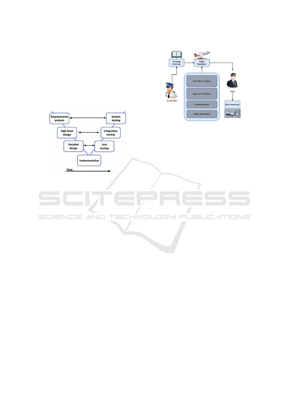
The V-Model allows the design and development
of complex mechatronic systems with an interdisci-
plinary method, where the VDI guideline 2206 can be
applied to obtain systems that are more flexible and
adaptable to the needs of users. The overall devel-
opment process follows the V-Model that is shown in
Figure 1 (Shuping and Ling, 2008; Fodor et al., 2019).
Figure 1: V-model approach used in structured systems de-
sign (Fodor et al., 2019), (Bruyninckx, 2008).
Initially all functional and non-functional require-
ments for the automatic flight control system are
defined in the top-level specification (the developed
cockpit performs the interface to the system whereas
the autopilot control is provided by Toliss). They are
gradually refined top-down from aircraft level via sys-
tem and assembly level to the hardware and software
requirements on component level. After encoding and
production, the gradual integration and verification
(bottom-up) follows. Each process step ends with ver-
ification tests. The final step includes validation tests
with the modules mirroring the data presented in the
game. In order to create a system that simulates the
cockpit of the Airbus A32x model on a real scale, the
system architecture shown in Figure 2 was developed.
The hardware and software used in this work were de-
veloped to always communicate with each other, so
the project takes the pilot in the training phase a real-
istic immersion during the simulation.
As is well known, there are many techniques and
procedures that a fresh pilot must study to complete
his/her flight license. Many of these techniques can
be extensively inserted and trained in this proposed
flight simulation. The entire process can be summa-
rized through Figure 2, as well as the description of
each topic below:
• Fresh Pilot: In this initial phase of training
with the simulated cockpit, the pilot must already
have in mind what type of flight license course,
Figure 2: System Architecture.
which classifications he/she wishes to acquire,
and which flights he/she intends to train.
• Training Protocols: The pilot must already have
a training plan at this stage because the license
has already been chosen, classification, and flights
to be trained in the simulator. So, the pilot must
adapt to the norms and standards required for the
chosen plan. For example, a pilot of Asian origin
could perform a flight simulation under conditions
and standards from Europe and without having to
go training in European territory.
• Flight Simulator: This part is when the flight
simulation happens, that is, when the fresh pilot
trains his/her skills in the simulated cockpit. The
aspiring pilot will find all the modules similar to
those found in the real aircraft, from the seats, but-
tons, indicators, and other elements present in an
Airbus A32x cockpit. Licensed pilots can still
maintain their degree of experience by training
situations they have already experienced in real
flight.
• Procedures Trainer: This tool is vital during pi-
lots’ training since the simulator is a copy almost
identical to that found in the aircraft. Therefore,
the pilot, together with his/her instructor, will
practice possible real flight situations. Thus, the
instructor will assist his/her student in a system
called Flight and Navigation Procedures Trainer
(FNPT), that is, to carry out training that includes
necessary procedures for navigation, classifica-
tion and reading of instruments, and malfunctions
procedures.
• Approach Training: This training can be imple-
mented for pilots who wish to approach different
runway types but in a simulated environment. In
this way, the pilot can choose from a list of op-
tions which airport he/she wants to perform the
Approach Training. In this simulator, the visual
SIMULTECH 2021 - 11th International Conference on Simulation and Modeling Methodologies, Technologies and Applications
258

system implemented makes a reproduction of the
runway markings, runway lights, approach lights,
and also the Runway Aiming Points (primary and
secondary).
• Communications: In addition to navigation
skills, the postulant pilot must also undertake
communication training. This Communication
training simulates the cooperation between the
crew or simulates the pilot’s communication with
the Radio Station Control. Thus, it avoids pos-
sible problems with interactions between people
with different types of pronunciation.
• Safety Procedures: The instructor can also add
safety procedures to the novice pilot’s plan, such
as emergency escape, fire alarm, and emergency
stops.
• Pilot and Real Situations: After exhaustively
conducting numerous simulations, the instructor
will evaluate his/her student to start the tests in
real flight situations. Thus, the beginner pilot will
be able to perform better in testing his/her flight
license.
4 HARDWARE AND SOFTWARE
DEVELOPMENTS
As stated before, this work aims to develop a flight
simulation platform as close as possible to the real
models. In this sense, the developed cockpit imple-
ments all system interfaces that can be found in the
real cockpit of an A32x. This includes all overhead
panel, main panel, Glare-shield, Pedestal and side
bases systems.
Six displays are implemented in the main panel:
two independent Primary Flight (PFD), one for Cap-
tain and other for First Officer; two independent Nav-
igation Displays (ND) for Captain and First Officer;
and two ECAM displays the Engine / Warning Dis-
play (EWD) and and System Display (SD). The dis-
plays show the information sent by the XHSI (eXter-
nal High-resolution Simulator Instruments) applica-
tion and are controlled by the hardware implemented
in the cockpit.
On the captain side, there is the PFD (Primary
Flight Display) with flight parameters, such as the
horizon, speed, altitude, and some extra information
regarding the flight. Then there is the Navigation Dis-
play (ND) that presents a fundamental information to
the navigation, such as the flight plan, way-points,
Navaids, and airports. It can also include the weather
information gathered from the radar and terrain info.
Moreover, the screens info configuration can be ad-
justed by the Electronic Flight Instrument System
(EFIS) placed above the glare shield (to reduce the
effects of glare) near the autopilot commands. It al-
lows selecting several modes, such as LS, VOR, NAV,
ARC, and PLAN.
At the central panel, there is some information
provided by the monitors that can be extracted by
the FCOM (Flight Crew Operating Manual), among
the others: Primary engine indications, fuel quantity,
flap and slat position; Warning and caution alerts, or
memos; Synoptic diagrams of aircraft systems, and
status messages; Permanent flight data.
This structure was followed faithfully, as can be
seen in the results section.
4.1 Cyber-Physical Systems
New challenges have emerged due to the development
of recent technologies, among them is the CPS. This
concept refers to integrating numerous techniques,
such as computing, data network, and data acquisition
system through sensing. Therefore, this integration
process can provide a distributed and autonomous
systems. In other words, the CPS performs a friendly
coupling between the cybernetic and physical com-
ponents (software and hardware); the sensor systems
usually do this coupling. For a CPS system to be suc-
cessful, it is necessary to model each stage of inte-
gration correctly. The modeling will be a link, or a
translator, between the physical and cybernetic envi-
ronments.
As indicated by (Rajkumar et al., 2010), applica-
tions using CPS will have a significant impact in a
wide variety of areas. The aeronautics sector would
not be left out. One of the possible applications of
CPS in the aeronautics sector can be seen in flight
simulation situations, where the devices in the real
cockpit could be modeled to show information in the
simulated environment. For example, the use of ped-
als in a cockpit could be synchronized with the pedal
in the simulated cockpit. Thus, when the pilot is train-
ing his/her flight skills and activates the pedal in the
training cockpit, consequently the pedal in the graphic
simulator will also be activated at the same intensity.
This process could happen for all types of devices
and settings that exist in the Airbus A32x cockpit,
from buttons, indicators, sensors, mechanical parts,
among others. For this to happen, it is necessary to do
each one’s modeling since (as previously mentioned).
However, this work’s focus is not to describe these
components’ modeling due to the degree of complex-
ity and detail required to perform the CPS of this
cockpit.
Real Cockpit Proposal for Flight Simulation with Airbus A32x Models: An Overview Description
259
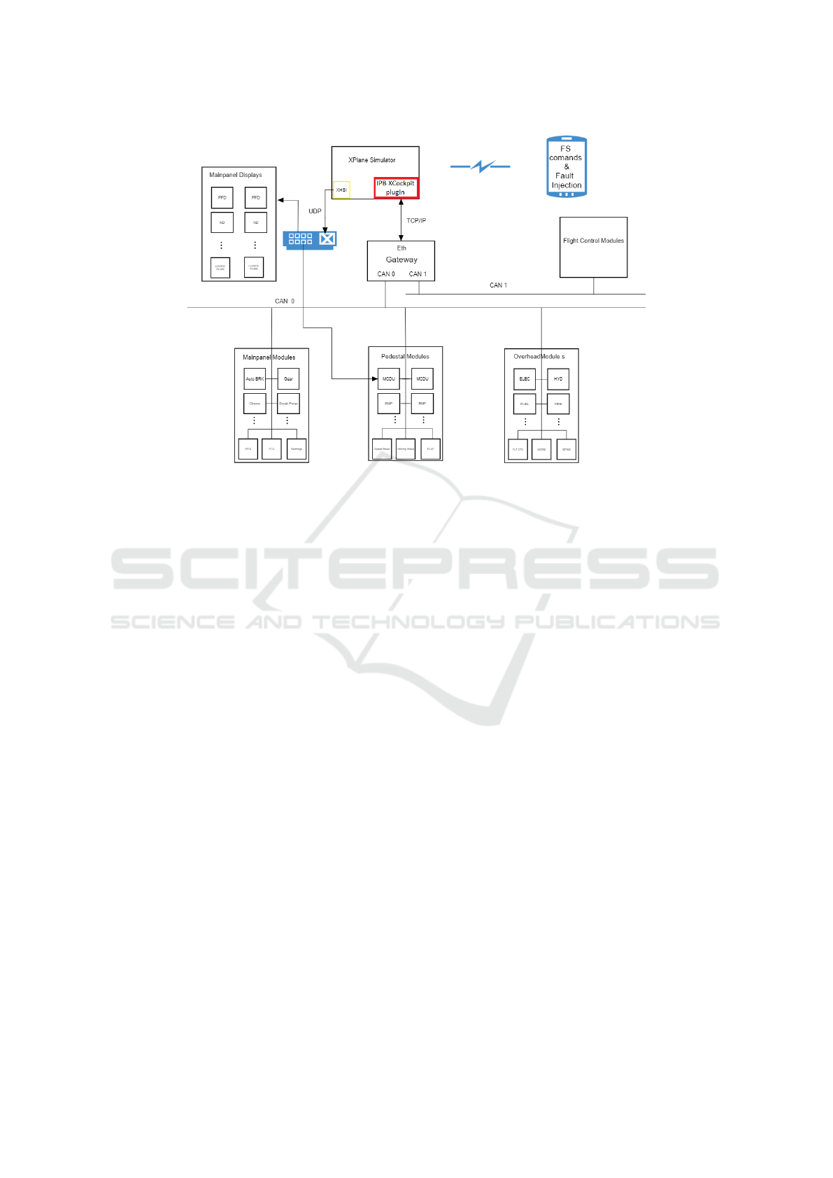
Figure 3: Main system architecture.
4.2 Software and Hardware
Components
The proposed system is mainly composed of the
X − Plane Simulator setting (Meyer, 2011). Al-
though several simulators like Microsoft’s Flight Sim-
ulator and FlightGear, the X −Plane was chosen since
it provides exceptionally accurate aerodynamic and
flight models and allows for real-time data to be sent
into and out of the program as well as the airfoil de-
sign. Different from the Microsoft Flight Simulator,
the X − Plane allows input from and output to exter-
nal sources. While FlightGear (Berndt, 2020) has I/O
capabilities similar to X − Plane, it is not relatively
stable and does not provide the same level of support.
For all these reasons, the X − Plane was chosen to be
used in the HIL simulator. The operation principle of
X − Plane is based on reading the geometric shape of
any aircraft and then predicting how that aircraft will
fly. The aircraft is divided into small elements, and
then the forces on each element are calculated on an
engineering process named “blade element theory”.
Based on the aircraft’s mass and center of gravity, the
forces are converted into accelerations, which are in-
tegrated to generate velocities and positions. All these
variables are managed by a dynamics engine embed-
ded in the game. X − Plane is certified by the U.S.
Agency of Aviation (FAA - Federal Aviation Admin-
istration) to train pilots. Its method ensures a reli-
able system since it is much more detailed, flexible,
and advanced than the flight model based on stability
derivatives used by most other flight simulators. The
controllers developed and tested in X − Plane plat-
forms have been successful when embedded in real
aircraft (Garcia and Barnes, 2009) adding more cred-
ibility to the results obtained in this work. An impor-
tant feature of X − Plane is the capability to commu-
nicate flight data via UDP (User Datagram Protocol)
connection using the IEEE754 format, as well as the
ability to exchange information with the external en-
vironment.
The developed cockpit uses a plugin to communi-
cate with clients and servers based on callback func-
tions.
The chosen airplane model for this work is an
A32x, a member of the Airbus A320 family of short-
to medium-range, narrow-body, commercial passen-
ger twin-engine jet airliners manufactured by Airbus.
The simulation environment is being executed on
a desktop PC with a core I9-9900K Processor, 32Gb
DDR4 memory, a Nvidia
T M
GeForce
T M
RTX 2080
Ti graphics card and a solid-state drive. This system
is powered by a 1 kW power supply. All the con-
nections to the cockpit instruments are based on Eth-
ernet, as it can be presented by figure 3. There are
two main connections established that uses UDP and
TCP to send and receive information to the developed
modules. Moreover, it will further be able to receive
faults injection by a mobile device.
The main panel displays (PFD’s, ND’s, EWD,
SD and MCDU’s pedestal displays) are connected
by the UDP protocol using XHSI. The XHSI mod-
SIMULTECH 2021 - 11th International Conference on Simulation and Modeling Methodologies, Technologies and Applications
260
ule, that is an add-on for the X-Plane flight simu-
lator and displays the PFD, ND, ECAM (Electronic
Centralized Aircraft Monitor), Flaps and Gear indi-
cator, Clock/Chronometer, etc... sends data to the
displays each one connected to a rapsberry pi. The
raspberry pi accesses to the mainpanel monitor with a
HDMI, VGA, DVI, and LCD Control board work for
10.4inch G104X1 L04 1024x768 LCD panel.
On the other side, the TCP connection will handle
the communication to the panels instruments, such as
buttons, lights, actuators among others.
The CAN/ETH gateway connects most cockpit
buttons and commands and the information is sent be-
tween cockpit and simulator PC or simulator cockpit
via TCP/IP, i.e. messages are confirmed by the pro-
tocol. In the case of PFD, ND, ECAM and MCDU
displays on the pedestal the information is not con-
firmed and sent by UDP (multicast). This has every-
thing to do with performance. It is not necessary to
confirm the message because in case of error the next
message refreshes the displays with correct info.
For that purpose, it was developed a plugin
(IPB XCockpit, detailed on Figure 4) that sends and
receives TCP packets from/to the Gateway. This gate-
way allows to connect the CAN0 and CAN1 buses
where all the modules are connected.
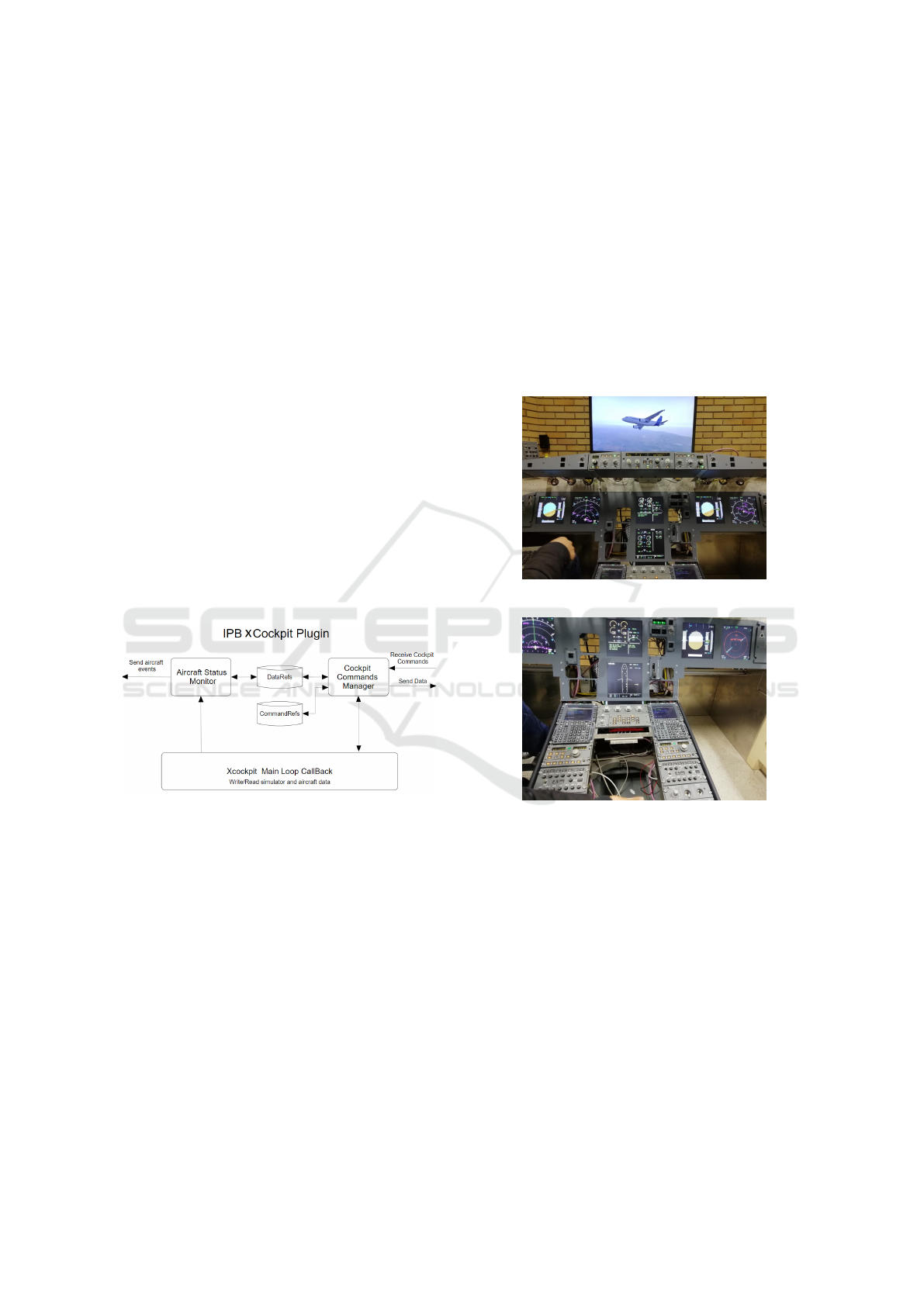
Figure 4: IPB XCockpit plugin detailed.
This developed IPB XCockpit plugin owns a
main loop callback that writes and reads the simula-
tor and aircraft data in order to feed the aircraft sta-
tus monitor and receives commands from the cock-
pit commands manager. This information is stored
into the data refs and command refs respectively. By
this way, it is possible that the cockpit instruments can
read the airplane variables and also control it.
5 RESULTS
The developed system is composed by software, hard-
ware and mechanical components. The mechanical
design of instruments and actuators is not the focus
of this paper. The software is executed on a computer
and communicates with a intelligent sensors network
using a gateway (Ethernet and CAN bused converter).
The intelligent sensor network is spread by all over
the cockpit as a modular approach. Some modules of
hardware and mechanical components are presented
in Figures 5 and 6. The first one shows the flight
screen on a wall television, the front panel composed
by the FCU (Flight Control Unit) where the Autopi-
lot controls are placed. The Barometer system are
installed on the Electronic Flight Instrument System
where warnings and master caution indicators are pre-
sented also. On the other hand, the radio controls and
communication system are presented on Figure 6.
Figure 5: Under development of frontal cockpit at IPB.
Figure 6: Under development of pedestal panel cockpit at
IPB.
All these developed modules are communicating
and the flight simulator assumes the variables intro-
duced by the user on the cockpit modules. It can
be validated by Figure 7 where it is possible to ob-
serve the EFIS and the FCU Flight Control Unit in
which autopilots can be activated either in direct or
managed mode. The BARO was configured, as exam-
ple on 29.92 in Hg. On EFIS, inside the PFD control
part, it is possible to choose between Hg and hPa and
using the encoder to enter the value of the baromet-
ric pressure or standard reference STD. The autopilot
was configured with a speed of 207 knots, a heading
of 23 degrees and an altitude of 19700 feet. As it
can be observed, the instruments of the flight (on the
wall television) assumed this parameters. As previ-
Real Cockpit Proposal for Flight Simulation with Airbus A32x Models: An Overview Description
261
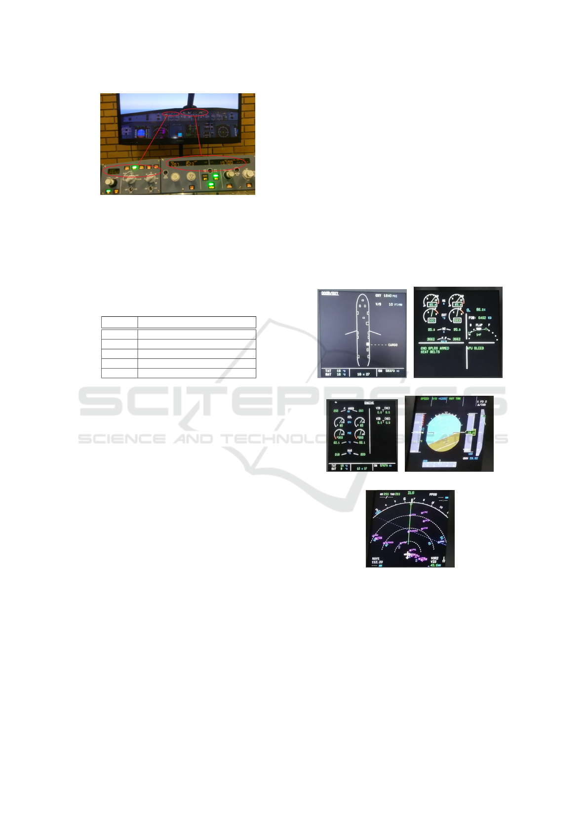
Figure 7: BARO and Autopilot control panel assuming the
programmed values at the developed cockpit validating the
communication between modules.
ously addressed, the monitors presented on the frontal
panel, will display information as the real cockpit.
Each monitor uses a Raspberry pi 4 and some exam-
ples are presented on Figure 8. Table 1 details each
screen information.
Table 1: Main panel Monitors description.
Monitor Description
(a) Door information (DOOR)
(b) Engine/Warning Display (E/WD)
(c) Engines (ENG)
(d) Primary Flight Display (PFD)
(e) Navigation Display (ND)
These monitors can be configured to show differ-
ent information and can be selected by the Electronic
Centralized Aircraft Monitor (ECAM) Control Panel.
It will be possible to use the wall television to show
the landscape and environment as the windows on
the real cockpit. As result, it was proposed a cock-
pit owning several instruments, monitors and controls
to make the flight simulation more realistic. All the
instruments were communicating with the simulator
allowing the pilot to have a flight experience more re-
lated with a real components instead of a television
emulated instruments.
6 CONCLUSIONS & FUTURE
WORK
The presented paper described the development of
a cockpit to be used for flight simulations of Air-
bus A32x. It presented the proposed mechanical
and hardware components as well as its communi-
cation based on Ethernet and CAN buses. The real
scale main panel of a cockpit was developed and
can be used to test pilots on flight task. The instru-
ments presented on panels, such as control buttons,
lights and displays were tested in several simulated
flights that validate the proposed approach. As imple-
mented examples are the FCU (Flight Control Unit),
the EFIS (Electronic Flight Instrument System), and
the ECAM (Electronic Centralized Aircraft Monitor)
control panel to select system pages on System Dis-
play. This modular approach had supported more than
fifty students working on this project. As it can be
noted, this paper presented a continuous working-in-
progress development of a real cockpit to be used in
simulation and there are several modules that can be
included. As future work direction, it can be pointed
out a projection based on three projectors using an im-
mersive methodology and other instruments that will
fit on the designed and planned, such as the develop-
ment of the Throttle control system with motorized
trim wheel, as well as the implementation of all over-
head panels such as Ligh, Elec, HYD/Fuel, Fire, FLT
CTL, ADIRS, Office and GPWS among the others.
(a) (b)
(c) (d)
(e)
Figure 8: Monitors of the front cockpit panel. Monitors
can be selected by the Electronic Centralized Aircraft Mon-
itor (ECAM) Control Panel a) Door information (DOOR),
b) Engine/Warning Display (E/WD), c) Engines (ENG), d)
Primary Flight Display (PFD) where horizon, speed and al-
titude information is presented, e) Navigation Display (ND)
with waypoints, navaids and airports localization.
SIMULTECH 2021 - 11th International Conference on Simulation and Modeling Methodologies, Technologies and Applications
262

ACKNOWLEDGEMENTS
This work has been supported by FCT - Fundac¸
˜
ao
para a Ci
ˆ
encia e Tecnologia within the Project Scope:
UIDB/05757/2020.
REFERENCES
Adiprawita, W., Ahmad, A., and Sembiring, J. (2008).
Hardware in the loop simulator in uav rapid develop-
ment life cycle. arXiv.
Berndt, J. (2020). Flightgear: an open-source flight simula-
tor.
Boril, J., Leuchter, J., Smrz, V., and Blasch, E. (2015). Avi-
ation simulation training in the czech air force. In
2015 IEEE/AIAA 34th Digital Avionics Systems Con-
ference (DASC), pages 9A2–1. IEEE.
Bruyninckx, H. (2008). V model from structured systems
design theory.
Casner SM, Geven RW, W. K. (2013). The Effectiveness of
Airline Pilot Training for Abnormal Events. Human
Factors.
Cen, F., Li, Q., Fan, L., Liu, Z., and Sun, H. (2015). De-
velopment of a pilot-in-loop real-time simulation plat-
form for wind tunnel free-flight test. In 2015 IEEE In-
ternational Conference on Information and Automa-
tion, pages 2433–2438. IEEE.
Chaudron, J.-B., Saussi
´
e, D., Siron, P., and Adelantado, M.
(2014). Real-time distributed simulations in an hla
framework: Application to aircraft simulation. Simu-
lation, 90(6):627–643.
Chudy, P. and Rzucidlo, P. (2012). Hil simulation of a light
aircraft flight control system. In 31th IEEE Digital
Avionics Systems Conference, pages 6D111–6D112.
IEEE.
Demers, S., Gopalakrishnan, P., and Kant, L. (2007). A
generic solution to software-in-the-loop. Military
Communications Conference 2007. MILCOM 2007.
Ellis, G. (2012). Chapter 13 - model development and
verification. In Ellis, G., editor, Control System
Design Guide (Fourth Edition), pages 261 – 282.
Butterworth-Heinemann, Boston, fourth edition edi-
tion.
Fodor, A., J
´
an
´
o, R., and Fizes
,
an, R. T. (2019). Charac-
terization of the v-model approach in thermal design
process. In 2019 IEEE 25th International Symposium
for Design and Technology in Electronic Packaging
(SIITME), pages 367–370.
Garcia, R. and Barnes, L. (2009). Multi-uav simulator uti-
lizing x-plane. In Selected papers from the 2nd In-
ternational Symposium on UAVs, Reno, Nevada, USA
June 8–10, 2009, pages 393–406. Springer.
Gervais, C., Chaudron, J.-B., Siron, P., Leconte, R., and
Saussi
´
e, D. (2012). Real-time distributed aircraft sim-
ulation through hla. In 2012 IEEE/ACM 16th Interna-
tional Symposium on Distributed Simulation and Real
Time Applications, pages 251–254. IEEE.
Gholkar, A., Isaacs, A., and Arya, H. (2004). Hardware-in-
loop simulator for mini aerial vehicle. Department of
Aerospace Engineering on IIT at Bombay, 2(2).
Gomez, M. (2001). Hardware-in-the-loop simulation. Em-
bedded System Design.
Hays, R. T., Jacobs, J. W., Prince, C., and Salas, E.
(1992). Flight simulator training effectiveness: A
meta-analysis. Military psychology, 4(2):63–74.
Kaden, A., Boche, B., and Luckner, R. (2013). Hardware-
in-the-loop flight simulator – an essential part in the
development process for the automatic flight control
system of a utility aircraft. In AIAA Modeling and
Simulation Technologies Conference and Exhibit.
Khan, A. H., Khan, Z. H., and Khan, S. H. (2014).
Optimized reconfigurable autopilot design for an
aerospace cps. In Computational intelligence for de-
cision support in cyber-physical systems, pages 381–
420. Springer.
Lofaro, R. J. and Smith, K. M. (2012). The aviation op-
erational environment: Integrating a decision-making
paradigm, flight simulator training and an automated
cockpit display for aviation safety. In Technology
Engineering and Management in Aviation: Advance-
ments and Discoveries, pages 241–282. IGI Global.
Lorains, M., MacMahon, C., Ball, K., and Mahoney, J.
(2011). Above real time training for team invasion
sport skills. International Journal of Sports Science
& Coaching, 6(4):537–544.
Louali, R., Belloula, A., Djouadi, M. S., and Bouaziz, S.
(2011). Real-time characterization of ms flight sim-
ulator 2004 for integration into hardware in the loop
architecture. In 19th Mediterranean Conf. on Control
& Automation (MED), pages 1241–1246. IEEE.
Merk, R. and Roessingh, J. (2016). Assessing behaviour of
cognitive agents in a flight simulator with fighter pi-
lots. In 2016 IEEE International Conference on Sys-
tems, Man, and Cybernetics (SMC), pages 004842–
004847. IEEE.
Meyer, A. (2011). X-plane operation manual.
Rajkumar, R., Lee, I., Sha, L., and Stankovic, J. (2010).
Cyber-physical systems: the next computing revolu-
tion. In Design automation conference, pages 731–
736. IEEE.
Sampaio, R. C. B., Becker, M., Freschi, L. W., and Mon-
tanher, M. P. (2013). Novel sil evaluation of an op-
timal h1 controller on the stability of a mav in flight
simulator. In Aerospace Conference, pages 186D11–
186D12. IEEE.
Scamps, A. and Gibbens, P. (2005). Development of a flight
simulator evaluation course at qantas. In AIAA Model-
ing and Simulation Technologies Conference and Ex-
hibit, page 6114.
Shuping, L. and Ling, P. (2008). The research of v model
in testing embedded software. In 2008 International
Conference on Computer Science and Information
Technology, pages 463–466.
Zhang, X. and Mi, C. (2011). Hardware-in-the-loop and
software-in-the-loop testing for vehicle power man-
agement. In In proceedings of Vehicle Power Man-
agement, Power Systems. Springer.
Real Cockpit Proposal for Flight Simulation with Airbus A32x Models: An Overview Description
263
