
Towards Real Time Predictive System for Mechanical Stamping Presses
to Assure Correct Slide Parallelism
Ivan Peinado-Asensi
1,2 a
, N. Montes
1 b
and E. Garc
´
ıa
2 c
1
Mathematics, Physics and Technological Sciences Department, University CEU Cardenal Herrera,
C/ San Bartolom
´
e 55, 46115, Alfara del Patriarca, Valencia, Spain
2
Ford Spain, Pol
´
ıgono Industrial Ford S/N, 46440, Almussafes, Valencia, Spain
Keywords:
Smart Stamping Plant, Real-time Data Analysis, Machine Health Monitoring, Predictive Maintenance.
Abstract:
Automotive companies are going through a rough time due to the decrease in the car sales market, therefore
OEMs trend is cost reduction in the next years over improving efficiency increasing digitalization, implement-
ing new industry 4.0 technologies to turn their facilities in smart factories. Within car manufacturing processes,
stamping present many possibilities for development, in this paper an approach to bring stamping plants closer
to smart factories is presented. The most common problems in stamping are unexpected breakdowns in equip-
ment and poor quality parts produced, to avoid these problems corrective and predictive maintenance tasks are
carried out to improve presses and tools performance. One of the critical maintenance tasks in press machines
are parallelism, a malfunction in the kinetic transmission can lead to high cost and duration breakdowns. To
monitor machine working parameters a novel method is presented using IIoT techniques, having access to
machine working parameters in Real-Time to predict machine malfunction in order to reduce the number of
breakdowns.
1 INTRODUCTION
Monitoring and Controlling press processes in the in-
dustrial stamping world has been widely developed to
ensure machinery lifetime and high quality in the fi-
nal product. But we are still having daily breakdowns
in the production lines in the factory due to equip-
ment failure and defects in the final product manu-
factured such as splits, necking and wrinkling among
others. The previous research in control processes has
followed four possible paths (Lim et al., 2013) to im-
prove performance. One of them is the die try-out
process where the objective is to analyze the tool (die
design) and the working variables. The second one
is controlling the blank holder force using finite el-
ements analysis (FEM). Other is based in in-process
control, a strategy to monitor the process inputs and
outputs during the stamping process. The last one is a
post-process control which part inspection is made to
identify significant variables.
Stamping machines need periodical maintenance
tasks to ensure correct functionality and avoid the
a
https://orcid.org/0000-0002-5603-5910
b
https://orcid.org/0000-0002-0661-3479
c
https://orcid.org/0000-0002-4210-9835
mentioned breakdowns, we need to know the com-
ponents status and fix them if required. Parallelism is
one of the main maintenance tasks that require time
and resources to carry it out and it is also important
to ensure a correct slide motion. The imbalance in the
slide is detected by the parallelism maintenance task,
this is carried out by setting the press in the Bottom
Dead Center without the die, placing the four posi-
tion gauge under each slide corner and next raising
the slide counterbalance pressure to lift the slide up
and then drop it to the initial position again, this is the
process carried out to measure slide clearance. Once
the clearance is known, again in the BDC we take a
slide corner as a reference and measure the distance
of every corner to the floor, thus it is possible to know
the balance difference in the corners. Once it is mea-
sured, the connecting rod feet are adjusted until the
parallelism of the slide is balanced. As explained, the
procedure is complex and requires a lot of time and
resources.
In this research we are going to make an approach
applying an in-process control methodology exploit-
ing the amount of data available through connected
devices employing Industry 4.0 technologies (e.g., In-
ternet of Things, Big Data Analysis) monitoring the
396
Peinado-Asensi, I., Montes, N. and García, E.
Towards Real Time Predictive System for Mechanical Stamping Presses to Assure Correct Slide Parallelism.
DOI: 10.5220/0010547203960402
In Proceedings of the 18th International Conference on Informatics in Control, Automation and Robotics (ICINCO 2021), pages 396-402
ISBN: 978-989-758-522-7
Copyright
c
2021 by SCITEPRESS – Science and Technology Publications, Lda. All rights reserved

variables of the machine, where exist up to 40 dif-
ferent variables to measure, among all the available
data we will procedure to identify and classify the
variables that are considered crucial in the process,
directly related with the slide parallelism to obtain in-
formation to identify working pathologies. In the fol-
lowing sections it will be explained which variables
and why are gonna be used to solve the parallelism
problem, with the goal of having a full knowledge
of the working state of the press in real-time. The
problem statement is to verify if it is possible to de-
tect the slide imbalance without requiring parallelism
maintenance task, skipping the process and the use of
the tools and sensors that are required to make it as
the procedure presented in (Magraner, 2016). To do
that a real-time monitoring tool has been developed
to know the slide gravity center and the friction in the
gibs. If the friction increase in some of the gibs or
the slide centre of gravity is displaced we could en-
sure that the parallelism is not correct. Once the vari-
ables are selected among the forty available, will be
of vital importance to verify if we can achieve to do
accurate predictions. Afterwards it will be needed to
define stamping working patterns to verify if the mon-
itored variables are reporting appropriate information
of the parallelism, if not it will requires to evaluate
new ones.
The purpose of the research is to know the slide
Gravity Center (GC) in order to control parallelism
and avoid component wear due to malfunction with
a predictive tool fed with data measures in Real-
Time following a procedure called Maintenance Sup-
port System (MSS) (Garc
´
ıa et al., 2018), and once
achieved, the following procedure will be to continue
monitoring new variables that cannot be measured us-
ing the usual procedures. In this paper a predictive
tool is proposed to know the GC of the slide in a cy-
cle motion of the press using the signal data from the
strain gauge available in the machine without required
installation to monitor the process in real time. The
motivation is to know the press working performance
through the GC in every moment, being able to know
the quality of the stamp punch, overloads, deviation
of the slide parallelism and the slide travel motion to
avoid premature wear due to friction in the press com-
ponents.
The paper is structured as follows: In section 2, an
overview of the research done in control and monitor-
ing in industrial stamping. In the next section 3, we
will explain the proposed physical model proposed
with the data required to get the friction variable. In
section 4 there is an explanation of how the data is
monitored and the result of the models using real-time
acquired data. In section 5 we will show the devel-
oped tool to find out the parallelism in real time. Fi-
nally, in section 6 we show the future work and the
conclusion.
2 MONITORING STAMPING
PROCESS
2.1 Equipment Description
Two main types of presses are used in sheet metal
forming, mechanical (Single-action (SA) or Double-
action (DA)) and hydraulic, both can be used in
all operations carried out in stamping (blanking,
deep-drawings and trimming) (Wagener, 1997). In
Ford Spain stamping plant most of the presses are
mechanical and the experiment of the research is
being carried out in a mechanical SA press with a
cushion system. The major difference between SA
and DA presses is the eccentric drive transmission
system and the blank holder force system. In SA
presses as seen in figure 1 there is one slide for the
tool and a cushion system as blank holder unlike DA
presses that have an eccentric drive system with two
slide displacements, one for the blank holder and
other for the tool holder. Double effect presses have
been used during years for deep drawing operations,
but recently they have been replaced by hydraulic
and SA presses with cushion because they are more
effective in deep-drawing operations (Hoffman,
1998).
As seen in figure 1, a stamping press is manufactured
of many different components such as the electrical
engine which activates press motion, the eccentric
transmission system which moves the slide upward
and downward controlling the speed press, the clutch
and brake hydraulic system, the slide counterbalance
cylinders that help electrical engine to raise the slide
and keep the torque of the activation system balanced
in the cycle, the slide where the die is fitted for each
production and height can be adjusted and also the
gibs in each of the press columns to guide the slide.
2.2 Process Control in Sheet-metal
Forming
There is much research based in methods that they
use data for monitoring working process, this research
mostly in close-loop and in-process control systems.
In last decades it has been easy to find research about
close-loop control as the one developed by (Siegert
et al., 1997) (Yagami et al., 2004) (Viswanathan et al.,
Towards Real Time Predictive System for Mechanical Stamping Presses to Assure Correct Slide Parallelism
397

Figure 1: Single-action mechanical press.
2003) in which the springback effect of the material
is controlled by the Blank Holder Force applied, con-
trolling the material flow when deep-drawing (Endelt
et al., 2013) and also eliminating the wrinkling and
fracture in rectangular parts (Ahmetoglu et al., 1995).
Also non-destructive test (NDT) have been used to
monitor data, in the case of (Ng et al., 2007) to di-
agnose the stamping quality, the 3D thermal distribu-
tion was analyzed, using the electromagnetism physi-
cal principle by installing electromagnetic coils in the
die surface (Shang and Daehn, 2011). There is much
research based too on Acoustic Emission in order to
detect bad parts (Song et al., 2016) or to detect tool
wear (Ubhayaratne et al., 2015).
Regarding to in-process control systems, in the
study carried out by Hardt and Fenn it was possible to
detect differences in material input such as lubrication
and material thickness (Hardt and Fenn, 1993), that
was a breakthrough in control monitoring because it
was possible to identify new variables in stamping
process. Hardt et all. used the data monitored from
the force punch combined with a previous close-loop
control developed to control the blank holder force.
Other effective process control designed was the one
proposed by (Hsu et al., 2002) in which they take into
account blank holder pressure, the sheet metal fea-
tures and the punch force showing that the process
can maintain the same punch force trajectories with
different lubrication conditions, but machine control
cannot.
Figure 2: Process control of sheet metal forming.
The proposed procedure is focusing on taking a
step forward, the idea is following in-process tech-
niques by monitoring the required data to analyze
working performance using Industry 4.0 technolo-
gies, but to carry it out a huge investment is needed
in order to buy and install proper equipment to get ac-
curate data and centralize the measurement system in
one platform. Furthermore, due to the currently situ-
ation in the automotive sector the OEMs are planning
to reduce costs. It is true that by increasing digitaliza-
tion and optimizing the efficiency of productions the
costs can be reduced, but a large initial investment is
required anyway. Therefore, we are going to apply
Industry 4.0 techniques avoiding this initial invest-
ment by acquiring the data from the sensors already
installed in the presses of the plant, and by develop-
ing the software in site to analyze the data and send
alarms to predict breakdowns.
3 MATHEMATICAL MODEL TO
MONITOR STAMPING
PROCESS DATA
Taking as starting point that the bad parallelism and
the imbalance in the transmission system leads to a
premature wear of the different components in the
press and this wear is caused because of the friction
between them, we can conclude that friction and im-
balance are directly relate. The aim of the data ac-
quisition is to obtain curves of all the available mea-
sured variables in the press, at least on value per each
press position, this means 360 values in a curve shape
of tonnage force, counterbalance pressure, overload
pressure, cushion pressure, etc. Therefore relating all
this data in a physical model could be possible to ob-
tain the friction force of different components.
Thus a physical model will be proposed in this
section to monitor the friction force variables in a
press. The model is going to be set in three stages.
Firstly, a model describing the downward motion
where the friction in the gibs and in the eccentric
transmissions systems can be obtained. Secondly, the
deep-drawing where the friction of the die surface
with the blank surface could be modelled and in the
ICINCO 2021 - 18th International Conference on Informatics in Control, Automation and Robotics
398
third stage, the upward motion of the slide where the
same friction force can be obtained as in downward
motion. So following the procedure used to monitor
the GC and thanks to the data acquisition system, a
physical model is presented to know the friction in the
slide gibs in real-time during the downward motion.
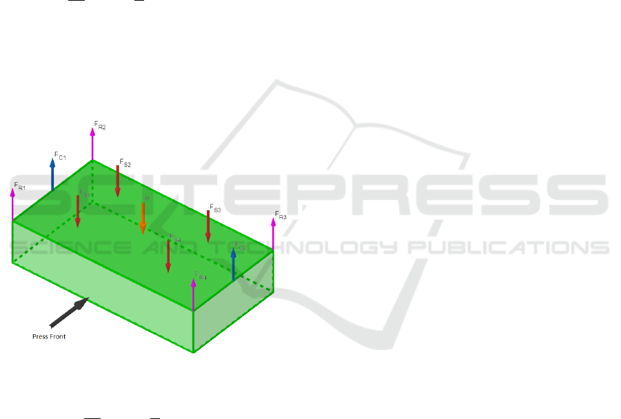
In picture 3 the loads considered in the model are
shown. The proposed model will be used to find
out the friction force in each press corner. So if we
consider the system as static in every press position
degree, where there is no downward movement and
therefore we will consider there is no friction in the
gibs, so for one corner it results,
F
C
i
2
− F
s
i
=
m
4
· a
x
, i = 1. (1)
Where F
C
is the slide counterbalance force, F
s
the
press force applied in the slide measured with the ton-
nage gauge sensor, m the upper die mass and a
x
the
acceleration of the slide in the downwards motion.
The model is used to describe the physical behaviour
in every corner of the press as described in picture 3.
Figure 3: Slide loads considered.
F
R
i
+
F
C
i
2
− F
s
i
=
m
4
· a
x
, i = 1. (2)
Considering the forces applied by the components in-
volved in the downward motion of the slide being F
R
the gib friction force. Now it is shown the result of
the physical model for the entire mobile system,
4
∑
i=1
(F
R
i
− F
s
i
) +
2
∑
i=1
F
C
i
= m · a
x
(3)
As it can be seen, the only parameter that is not known
is the friction force, which will be obtained from the
model proposed. Applying this equation to every
press position degree from 320
o
to 90
o
we are able
to control the friction force existing between the slide
and the gibs.
4 DATA ACQUISITION PROCESS
The standard which has already been implemented by
Ford in Valencia Factory to program the PLC to get
the data explained in (Garcia and Montes, 2019) al-
lowed to get direct connection to the already installed
sensors by the press manufacturer. Saving money in
the installation because the sensors to get the info are
already installed in the press except the acceleration,
the only variable needed that was not previously mon-
itored but whose installation was really easy as ex-
plained below.
The challenge at this point is to have enough scan
speed in the PLC to read all the required data in a
stamp cycle, so due to the slide motion it is carried out
in more or less 3.5 seconds and 360 values per sensor
which need to be read by the PLC and if there are nine
variables it is exactly 3240 values, it requires around
1 ms second of scan speed per cycle. After several
tests carried out in the installed PLC, it was proved
that no data was missing in the cycle. Therefore, the
data collection started to obtain the curves of the data
per cycle to calculate the friction force.
To know the slide acceleration parameter, of vital
importance in the proposed model, a cheap and sim-
ply solution has been carried out, having access to an
important variable without significant expense. An
accelerator sensors has been installed (detail in figure
5) in each corner of the slide, having the acceleration
in the whole motion cycle, the sensor was connected
through a switch to the PLC to be able to collect all
the data where the other variables are monitored. The
tonnage data is acquired from the gauge sensors in-
stalled in the columns of the press, there are four
gauge sensors installed which send the data through
the Helm switch to the PLC. The slide counterbalance
force has been read from the pressure sensor installed
in the pneumatic circuit of the system. There is just
one measure that is why in the model is divided by
four, taking it as proportional in each corner.
5 REAL-TIME PREDICTIVE
TOOL
The online tool presented is currently working with
tonnage force data, the press is equipped with a load
gauge sensor in each one of the connecting rods which
allow us to know the press force applied in the cy-
Towards Real Time Predictive System for Mechanical Stamping Presses to Assure Correct Slide Parallelism
399

Figure 4: Gravity Center in Real-Time.
cle. As far as it is known with the force carried out
by the press in each of the four rods it is possible to
obtain the gravity center of the slide. By getting the
data from the PLC and applying the calculus in our
tool we can find out the gravity center at every point.
The tool shows the gravity center in real-time at Bot-
tom Dead Center press position (180 degrees) where
the maximum press force is applied, depending on the
produced part on the machine where the experiment is
taking place the maximum force can be up to 2.1 ·10
6
(kg), close to the press limit which is 2.5 · 10
6
(kg).
Knowing the gravity center of a squared object where
some forces are applied is trivial, thus the process of
implementing it in the software, developed in site, and
also having the Ford standard platform to connect the
machine data to the data based in the cloud was not a
big deal, the result obtained is shown in picture 4.
Different areas are shown in the online platform 4,
at the top left you can see the GC displacement of the
slide in 2D at BDC press position, the red square in-
dicates the press working limit for that applied force
and the blue square delimits the size of the slide. At
the top right we can see the GC plotted in 3D, where
the z axis indicates the press force for each stamped
part. The graph at the bottom shows the data obtained
from the sensor signal selected. There is also a menu
where we can choose the date of the production when
the data needs to be analyzed, the sensor type needs
to be analyze and also to classify the data depending
on the manufactured body part, because depending on
the body parts produced the data can vary due to ma-
Figure 5: Accelerometer sensor location.
terial and die characteristics. There is also the option
to visualize the GC of a cycle curve as you can see in
picture 6.
The tool purpose is monitoring the gravity center
and check if there is any variation or pathology that
appears just in time which can give information about
the machine status. It is well known that a deviation
of the slide balance can lead to premature wear in the
eccentric motion transmission system, wear of the die
surface and also in the slide gibs, caused by friction
ICINCO 2021 - 18th International Conference on Informatics in Control, Automation and Robotics
400
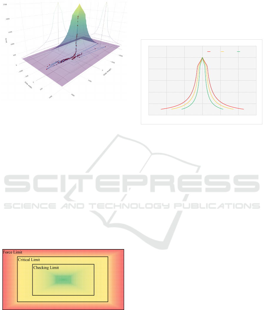
Figure 6: GC of a cycle.
increasing that may cause a lot of problems in the pro-
duced parts and the machine function. Knowing the
GC information in Real-Time can give us an advan-
tage to reduce maintenance activity, reduce mechan-
ical wear and reduce the set up press working force
and avoid parallelism checking extra works, all of that
can be achieved directly. Indirectly, electrical con-
sumption and repairing time can be reduced, break-
downs can be predicted and the life of the equipment
extended. All the improvements listed can bring cost
reductions.
5.1 Health Machine Monitoring
The next step is to know when the machine stops
operating under normal conditions and to identify
the problem that makes this happen. To do that, we
will send an alarm when the GC deviates from the
predefined boundaries. As seen in picture 7
Figure 7: X-Y section of limit surface force in 2D.
while the GC is still inside the green area we are
going to consider it to a normal function, once it
reaches the yellow area it will send an alarm to know
the behaviour of the press and check whether it is a
random hit with imbalance or a cumulative event of
hits out of the normal working area, if this happens
a technician will be sent to check the machine status.
When the hit reaches the red area the same procedure
as in the yellow area will be carried out but with an
exhaustive inspection and finally if it goes beyond of
the force limit line, the press will stop automatically.
0,00
500,00
1000,00
1500,00
2000,00
2500,00
3000,00
-3000 -2000 -1000 0 1000 2000 3000
Slide length
LIMIT FORCE X AXIS
Fx max Critical limit Cheking limit
Figure 8: X-Z section defining status limits in X axis.
Here in picture 7 we define the limits to identify
when the parallelism is deviating, these limits are de-
fined inside the red square at the top left graph in pic-
ture 4. To show the defined alarm area more precisely
in picture 8 you can see the surface in 2D from a right
profile view.
The same is defined in y axis and the result of the
shape of the different alarm area volumes can be con-
sidered as proportional surface with reduced volumes
inside the force limit surface that you can see at the
top right in picture 4. From the 360 points of the GC
obtained per cycle it will considered the percentage of
the points that there are in different area. The result
of the example curve showed before in the picture 6
there is a 100% of the values inside the green volume.
6 CONCLUSION
The research will continue monitoring the proposed
data in the physical model that is left to measure, fol-
lowing the same procedure carried out on the tonnage
force (such as counterbalance force and acceleration)
in the whole cycle and simulate the stamping cycle
to get the friction force. The cycle is divided into
3 stages. The first one, downward motion to know
the friction in the gibs, the second one is the same
in upward motion and the third one will be the deep-
drawing when more variables will be considered, such
as the the hydraulic cushion force, to get the friction
force between the die surface and the blank material.
To do that first it is required to extract a big amount of
data, check if the PLC is able to sent the data without
Towards Real Time Predictive System for Mechanical Stamping Presses to Assure Correct Slide Parallelism
401

loss of information, for later process the information
in our predictive tool.
Using industry 4.0 technology a tool developed to
control the machine in real time has been created, fol-
lowing the OEM trend of transform their current man-
ufacturing facilities in smart factories. The tool devel-
oped works as expected in real-time and give accurate
and valuable information about the slide state work-
ing, been able to control parallelism and friction in
the gibs reducing maintenance activity and premature
wear altogether with reduction of electrical consump-
tion. Furthermore the developed tool result as a ro-
bust and powerful method that gives a lot of opportu-
nities when talking about predictive maintenance and
knowing the machine health, taking the lead predict-
ing breakdowns.
ACKNOWLEDGEMENTS
This study was supported by the Universidad CEU
Cardenal Herrera, Ford Spain S.L. and Fundaci
´
on
para el Desarrollo y la Investigaci
´
on (FDI), Spain,
which the authors gratefully acknowledge.
REFERENCES
Ahmetoglu, M., Broek, T., Kinzel, G., and Altan, T. (1995).
Control of blank holder force to eliminate wrinkling
and fracture in deep-drawing rectangular parts. CIRP
annals, 44(1):247–250.
Endelt, B., Tommerup, S., and Danckert, J. (2013). A
novel feedback control system–controlling the ma-
terial flow in deep drawing using distributed blank-
holder force. Journal of Materials Processing Tech-
nology, 213(1):36–50.
Garcia, E. and Montes, N. (2019). Mini-term, a novel
paradigm for fault detection. IFAC-PapersOnLine,
52(13):165–170.
Garc
´
ıa, E., Mont
´
es, N., and Alacreu, M. (2018). Towards
a knowledge-driven maintenance support system for
manufacturing lines. In ICINCO (1), pages 53–64.
Hardt, D. E. (1993). Modeling and control of manufacturing
processes: getting more involved.
Hardt, D. E. (2017). Forming processes: Monitoring and
control. The Mechanical Systems Design Handbook:
Modeling, Measurement, and Control.
Hardt, D. E. and Fenn, R. C. (1993). Real-time control of
sheet stability during forming.
Hoffman, H. (1998). Metal forming handbook. Springer
Science & Business Media.
Hsu, C.-W., Ulsoy, A., and Demeri, M. (2000). An ap-
proach for modeling sheet metal forming for process
controller design. J. Manuf. Sci. Eng., 122(4):717–
724.
Hsu, C.-W., Ulsoy, A., and Demeri, M. (2002). Develop-
ment of process control in sheet metal forming. Jour-
nal of Materials Processing Technology, 127(3):361–
368.
Lim, Y., Ulsoy, A. G., and Venugopal, R. (2013). Process
control for sheet-metal stamping. Springer.
Lim, Y., Venugopal, R., and Ulsoy, A. (2012). Auto-tuning
and adaptive stamping process control. Control Engi-
neering Practice, 20(2):156–164.
Lim, Y., Venugopal, R., and Ulsoy, A. G. (2008). Advances
in the control of sheet metal forming. IFAC Proceed-
ings Volumes, 41(2):1875–1883.
Lim, Y., Venugopal, R., and Ulsoy, A. G. (2010). Multi-
input multi-output (mimo) modeling and control for
stamping. Journal of dynamic systems, measurement,
and control, 132(4).
Magraner, E. G. (2016). An
´
alisis de los sub-tiempos
de ciclo t
´
ecnico para la mejora del rendimiento de
las l
´
ıneas de fabricaci
´
on/tesis doctoral presentada
por Eduardo Garc
´
ıa Magraner; dirigida por Nicol
´
as
Mont
´
es S
´
anchez. PhD thesis, Universidad CEU-
Cardenal Herrera.
Maugin, G. (1980). The method of virtual power in con-
tinuum mechanics: application to coupled fields. Acta
Mechanica, 35(1):1–70.
Ng, Y.-M. H., Yu, M., Huang, Y., and Du, R. (2007). Di-
agnosis of sheet metal stamping processes based on
3-d thermal energy distribution. IEEE transactions on
automation science and engineering, 4(1):22–30.
Shang, J. and Daehn, G. (2011). Electromagnetically as-
sisted sheet metal stamping. Journal of Materials Pro-
cessing Technology, 211(5):868–874.
Siegert, K., Ziegler, M., and Wagner, S. (1997). Closed
loop control of the friction force. deep drawing pro-
cess. Journal of materials processing technology,
71(1):126–133.
Song, J., Kim, S., Liu, Z., Quang, N. N., and Bien, F.
(2016). A real time nondestructive crack detection
system for the automotive stamping process. IEEE
Transactions on Instrumentation and Measurement,
65(11):2434–2441.
Ubhayaratne, I., Xiang, Y., Pereira, M., and Rolfe, B.
(2015). An audio signal based model for condition
monitoring of sheet metal stamping process. In 2015
IEEE 10th Conference on Industrial Electronics and
Applications (ICIEA), pages 1267–1272. IEEE.
Viswanathan, V., Kinsey, B., and Cao, J. (2003). Experi-
mental implementation of neural network springback
control for sheet metal forming. J. Eng. Mater. Tech-
nol., 125(2):141–147.
Wagener, H.-W. (1997). New developments in sheet metal
forming: sheet materials, tools and machinery. Jour-
nal of materials processing technology, 72(3):342–
357.
Yagami, T., Manabe, K.-i., Yang, M., and Koyama, H.
(2004). Intelligent sheet stamping process using seg-
ment blankholder modules. Journal of Materials Pro-
cessing Technology, 155:2099–2105.
ICINCO 2021 - 18th International Conference on Informatics in Control, Automation and Robotics
402
