
Study of Polymers for the Implementation of an Axial Impeller with a
Central Shaft in a Ventricular Assist Device
Johanna Mu
˜
noz-P
´
erez
1,3 a
, Carlos Jim
´
enez-Carballo
2 b
, Gabriela Ortiz-Le
´
on
3 c
and Marta V
´
ılchez-Monge
3 d
1
Master Program in Medical Devices Engineering, School of Materials Science and Engineering,
Instituto Tecnol
´
ogico de Costa Rica, Cartago, Costa Rica
2
School of Physics, Instituto Tecnol
´
ogico de Costa Rica, Cartago, Costa Rica
3
Academic Area of Mechatronics Engineering, Instituto Tecnol
´
ogico de Costa Rica, Cartago, Costa Rica
Keywords:
VAD, FSI, FEM, Biocompatible Polymers, Failure Criteria.
Abstract:
The main goal of the present research was to determine the value of the mechanical parameters with which a
material to be used in a blood pump impeller must comply. To obtain these values, multiphysical numerical
simulation and modeling of the Fluid-Structure Interaction (FSI) of the impeller with defined conditions and
geometry was carried out, by means of Computational Fluid Dynamics (CFD) based on the Finite Element
Method (FEM), specifically the partitioned procedure was used. As a result of the simulations, the deformed
geometries, the maximum values of the Von Mises stress and the volumetric deformations for an axial impeller
with a central shaft were obtained. From this research it was determined that from the structural point of view
the selected biocompatible polymers are candidates for the manufacture of the impeller.
1 INTRODUCTION
In 2011 began the development of a ventricular assist
device (VAD) at the Instituto Tecnol
´
ogico de Costa
Rica (TEC) (Ortiz-Le
´
on et al., 2012), (Ortiz, 2017),
(Ortiz-Le
´
on et al., 2014). Previous research reveals
that the main drawback of introducing a blood pump
into the body of a living being, are the adverse ef-
fects that this device causes in the blood fluid, that is,
hemolysis and thrombosis (Tchantchaleishvili et al.,
2014) that could be related to the materials used in
the manufacture of the impeller.
On the other hand, increasing the lifespan of the
device is an important goal in order to extend the time
a person can carry it implanted before reaching a crit-
ical condition. Any improvement in the performance
of a blood pump in terms of avoiding these adverse
effects represents a significant advance from the point
of view of the patient and the economic cost of main-
taining the device.
a
https://orcid.org/0000-0003-1778-414X
b
https://orcid.org/0000-0003-1783-3159
c
https://orcid.org/0000-0002-0940-2677
d
https://orcid.org/0000-0002-3271-2569
The main goal of this research is to determine
the value of the mechanical parameters that the ma-
terial to be used in a blood pump impeller must meet.
Specifically, it is desired to introduce the fluid struc-
ture interaction model to the mathematical modeling
of the impeller, in order to visualize the effect that the
operation of the impeller has on the structure itself.
In other words, it seeks to determine the distribution
of stresses and deformations due to the fluid-structure
interaction and then to determine the ranges of defor-
mation and mechanical resistance that do not compro-
mise the functionality of the impeller. Finally, based
on the above, it is desired to determine a list of bio-
compatible polymers whose mechanical characteris-
tics are within the required ranges.
Therefore, this document is structured as follows:
in section 2 a description and list of biocompatible
materials is presented, in section 3 the failure criteria
used are explained, in section 4 the methodology used
for the fluid-structure interaction of the impeller is
mentioned, in section 5 the results obtained by means
of simulation are presented including the visualiza-
tion of the points subjected to greater stress and fi-
nally, conclusions about the pertinency in the use of
the studied materials for the desired application are
obtained.
142
Muñoz-Pérez, J., Jiménez-Carballo, C., Ortiz-León, G. and Vílchez-Monge, M.
Study of Polymers for the Implementation of an Axial Impeller with a Central Shaft in a Ventricular Assist Device.
DOI: 10.5220/0010815900003123
In Proceedings of the 15th International Joint Conference on Biomedical Engineering Systems and Technologies (BIOSTEC 2022) - Volume 1: BIODEVICES, pages 142-148
ISBN: 978-989-758-552-4; ISSN: 2184-4305
Copyright
c
2022 by SCITEPRESS – Science and Technology Publications, Lda. All rights reserved

2 BIOCOMPATIBLE POLYMERS
The FDA defines a medical device as “an implant, in-
tended for use in the mitigation, treatment, or pre-
vention of disease, and which does not achieve its
primary intended purposes through chemical action”
(FDA, 2018). An implant or device must be able to
maintain its functionality within the biological envi-
ronment of the body, complying with chemical, me-
chanical, electrical or thermal requirements.
The biocompatibility of a material is defined in
simple terms as its ability not to cause adverse effects
on body tissues. Achieving an adequate host response
due to interaction with a material involves identify-
ing and characterizing tissue reactions and adverse re-
sponses that could lead to the failure of the biomate-
rial, medical device or prosthesis. The assessment of
biocompatibility is considered a measure of the mag-
nitude and duration of adverse alterations that deter-
mine host response (Anderson, 2012).
Biomaterials are prepared using metals, ceramics
and polymers. Ceramics have good biocompatibility,
corrosion resistance, compressive strength and high
density. Some disadvantages of ceramics include its
fragility, low fracture resistance, low mechanical re-
liability, and complicated manufacturing processes.
Metals have high ductility, wear resistance and high
density. Polymers can be easily manufactured in com-
plex shapes and structures, however they do not al-
ways meet the mechanical requirements of the appli-
cation while sterilization processes could affect the
properties of the polymer (Teo et al., 2016) (Claver
´
ıa
and Pu
´
ertolas, 2011).
For this research, the studied polymers are listed
bellow:
1. TECAPEEK: Polyetheretherketone
2. PC: Polycarbonate
3. PMMA: Polymethyl Methacrylate
4. PP: Polypropylene
5. UHMW-PE: Ultra High Molecular Weight
Polyethylene
Table 1 shows the values required to perform
the structural simulations of the different materials:
Young’s modulus (E), elastic limit (σ
Y
), density (ρ)
and Poisson ratio (ν). These values are obtained from
the corresponding data sheets of each material, con-
sidering that a medical use spectrum was selected for
each type of polymer and if possible where its appli-
cation in implantable devices is indicated (Teo et al.,
2016), (Matarneh et al., 2018).
Table 1: Mechanical properties of the selected polymers.
Material E σ
Y
ρ ν
(GPa) (MPa) (kg/m
3
)
Tecapeek 4.4 117 1400 0.40
(Ensinger, 2020)
PC 2.3 60 1200 0.37
(Sabic, 2020)
PMMA 1.6 31 1090 0.36
(Campus, 2020)
PP 1.45 35 920 0.43
(Ensinger, 2017b)
UHMW-PE 0.66 22.2 936 0.46
(Ensinger, 2017a)
3 MATERIALS FAILURE
CRITERIA
If external forces are applied to a deformable body,
internal forces try to counteract these external forces.
The simplest way to analyze these internal forces
and the deformation generated by external forces on
the body is through the concept of stress τ
i j
(James,
2004).
If a body is sectioned in several planes parallel to
the coordinate axes, it is possible to obtain a volume
element where the state of the different stresses is rep-
resented. In this way the volume element has three
components of stress that act on each of its faces. The
nine components of the volume element stress make
up the second-order stress tensor σ. This tensor is
presented in equation 1. Also, if an infinitesimal ele-
ment is considered to be unable to transfer moments,
then τ
i j
= τ
ji
, implying that the tensor is symmetric
(Rosler et al., 2007).
σ =
σ
xx
τ
xy
τ
xz
τ
yx
σ
yy
τ
yz
τ
zx
τ
zy
σ
zz
=
σ
11
σ
12
σ
13
σ
21
σ
22
σ
23
σ
31
σ
32
σ
33
(1)
Study of Polymers for the Implementation of an Axial Impeller with a Central Shaft in a Ventricular Assist Device
143
For metallic materials, the von Mises failure crite-
rion is normally used. First, an equivalent stress is
defined and compared to the critical stress or elas-
tic limit of the material (σ
Y
). If the equivalent von
Mises stress σ
v
is greater than the critical stress σ
Y
,
the metal material is considered to fail. From the nor-
mal stresses (σ
ii
) and the shear stresses (σ
i j
), this fail-
ure criterion can be expressed as (Ugural and Fenster,
2011)
σ
v
=
r
1
2
σ
2
a
+ 3
σ
2
23
+ σ
2
13
+ σ
2
12
≥ σ
Y
, (2)
with
σ
2
a
= (σ
11
−σ
22
)
2
+(σ
22
−σ
33
)
2
+(σ
11
−σ
33
)
2
. (3)
For any stress tensor there is a coordinate system
where only the diagonal components of the tensor
remain, while all parts outside the diagonal become
zero. In this coordinate system, all stresses are nor-
mal and are called the principal stresses of the stress
tensor. The axes of the coordinate system are called
principal axes and the principal stresses are denoted
by Arabic numbers: σ
1
≥ σ
2
≥ σ
3
. The diagonalized
stress tensor is presented in equation 4 (Rosler et al.,
2007).
σ
diagonalized
=
σ
1
0 0
0 σ
2
0
0 0 σ
3
(4)
Using the principal stresses (σ
1
, σ
2
and σ
3
) the
failure criterion is expressed as
σ
v
=
r
1
2
h
(σ
1
− σ
2
)
2
+ (σ
1
− σ
3
)
2
+ (σ
2
− σ
3
)
2
i
≥ σ
Y
,
(5)
For polymeric materials and ceramics, the failure
criterion establishes that the principal stresses σ
i
(i =
1,2,3) are greater than σ
Y
or σ
UT S
(Ultimate Tensile
Strength for ceramics) (Mayorga-Espinoza, 2018).
1
σ
Y
σ
i
. (6)
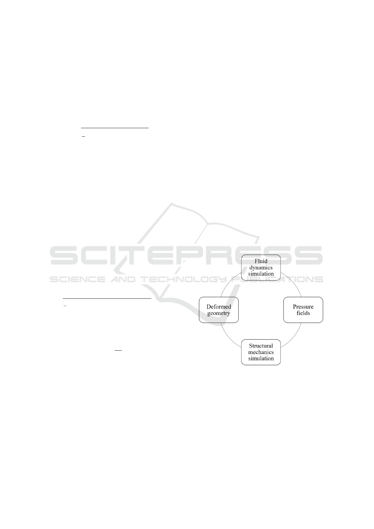
4 METHODOLOGY
A literature review shows that the main strategies used
for solving Fluid-Structure Interaction (FSI) problems
are (Rugonyi and Bathe, 2001), (Pedro and Sibanda,
2012):
• Simultaneous procedure in which the complete
system is solved as a single entity, which means
that the equations of fluid mechanics and those
of structural mechanics are solved simultaneously
(Park et al., 1977).
• Partitioned or iterative procedure where the solu-
tion of the process is developed in stages, for ex-
ample first the fluid field (or the structural one) is
solved and with the obtained solution the second
field is solved. Later with these solutions the first
field is solved again, and thus it is continued it-
eratively until convergence is reached (Farhat and
Lesoinne, 2000).
Initially, the integration of the fluid and the struc-
ture was proposed to simulate simultaneously the de-
formation experienced by the geometry under study
and the modifications that this new deformed geom-
etry caused in the fluid. However, the computational
resources of this approach are very demanding, so it
was necessary to divide the study into two simulations
(Mayorga-Espinoza, 2018).
Therefore, in this research the second procedure is
used as follows: first it begins with the resolution of
the equations of Navier-Stokes which allows to obtain
the velocity fields, the pressure fields and other hy-
drodynamic quantities. These results are then used
as boundary conditions in the deformable structure
to obtain stresses, velocities, accelerations and defor-
mations of the solid body. The process described to
achieve fluid-structure interaction is shown in figure
1 (Mu
˜
noz-P
´
erez, 2021).
Figure 1: Fluid-structure interaction process.
5 RESULTS
5.1 Fluid Simulations
As indicated in section 4, the strategy used to solve
the FSI problem posed in this research is the parti-
tioned procedure, this is because it was considered
that the impellers only suffer small deformations . It
BIODEVICES 2022 - 15th International Conference on Biomedical Electronics and Devices
144

is important to note that simulations were developed
with the help of the COMSOL Multiphysics
®
pro-
gram.
During the development of the partitioned
method, the results obtained from the fluid simula-
tion carried out in (Ortiz, 2017) on the geometry and
pressure fields for a rotational speed ω of 10500 rpm
(Reul and Akdis, 2000), (Song et al., 2003) and four
output speeds of the blood v (0.25 m/s, 0.50 m/s, 0.75
m/s and 1.00 m/s) were used. The behavior of blood
was modeled using a Newtonian, incompressible and
k-ε turbulence flow model, with a dinamic viscosity
of 0.0035 Pa·s and a density of 1052.82 kg/m
3
.
Boundary conditions of pressure and velocity
were used at the impeller inlet and outlet, respectively.
The pressure diference between the inlet and outlet
of the impeller is 40 mmHg. To simulate continuity
condition between the fixed and rotational domain in-
terface, the continuity boundary condition was used
(Ortiz, 2017). Figure 2 shows the graph of the pres-
sure distribution in the impeller structure for the case
where the rotational speed ω is 10500 rpm and the
blood output speed v is 1.00 m/s.
The pressure distribution in figure 2 shows that
the greatest pressure is obtained in the section of the
blades of both the impeller and the diffuser. In ad-
dition, the diffuser shaft has a greater pressure dif-
ference compared to the impeller and infuser shaft.
Zones with negative pressures correspond to regions
where the fluid moves faster.
5.2 Structural Simulations
Next, the structural simulations were carried out
where the results of the mentioned pressure fields
were used as boundary conditions in a deformable
solid model of the selected program, this is to sim-
ulate the steady state condition of the impeller. At the
same time, the impellers were subjected to the oscil-
lating load characteristic of the pulsations of the sys-
tem according to the cardiac cycle equation (Araya-
Luna, 2012).
The results of the simulations are presented in ta-
ble 2 where t is the time in which the greatest vol-
umetric deformation is reached, σ
i
is the principal
stress, p is the highest surface pressure, d
M
is the
maximum displacement, ε
V
is the unit volumetric de-
formation and σ
Y
/σ
i
is the ratio between the elas-
tic limit and the principal stress. These simulations
were run with a time-dependent study for four sec-
onds, which is equivalent to four cardiac cycles.
Based on table 2 the maximum displacements of a
point in the geometry d
M
are in the order of magnitude
of µm. Besides, it was found that the maximum unit
volumetric deformation ε
V
is equal to 28.649 × 10
−5
for UHMW-PE and the minimum value is equal to
6.7379 × 10
−5
for Tecapeek. Both parameters are
negiglible compared to the dimensions of the struc-
ture.
On the other hand, the relationship σ
Y
/σ
i
shown
in table 2 all materials meet the design criteria since
the relationship between their elastic limit and princi-
pal stress for any v is greater than 10. Regarding the
relationship σ
Y
/σ
i
, it is found that Tecapeek is the
most resistant material, which is explained because
it has the highest Young’s modulus of 4.4 GPa. It
is also observed that a Young’s modulus around 0.66
GPa seems potentially suitable for the impeller appli-
cation. Table 2 shows that the UHMW-PE for an out-
put speed v of 0.25 m/s has the lowest ratio σ
Y
/σ
i
,
that is, the highest structural stress.
The von Mises stresses and deformed geometry in
the impeller with a central shaft using UHMW-PE for
an output velocity v of 0.25 m/s are shown in Figure 3,
in which it can be seen that there is no significant dif-
ference between the deformed surface and the unde-
formed surface. It is evident from figure 3 that for the
entire structure the stresses of the greatest magnitude
are concentrated in the diffuser blades that are located
towards the output. Figure 4 shows a ZY view where
the stresses in the diffuser can be seen in greater de-
tail, in which the surface in red color corresponds to
the attack area of the moving fluid. According with
both figures, the maximum von Mises stress of 0.492
MPa is lower than the σ
Y
for this material (table 1),
which implies that this structure meets the design cri-
teria as established by equation 5.
In agreement with the results obtained from the
simulations carried out, it is clear that the polymers
used are suitable for the construction of an impeller
with a central shaft, at least from the structural point
of view.
6 CONCLUSIONS
This paper presents the mechanical properties for five
biocompatible polymers to be used in a blood pump
impeller. These includes the deformed geometries,
the maximum values of the Von Mises stress and the
volumetric deformations for the axial impeller with a
central shaft.
Firstly, a partitioned mathematical model was de-
veloped for the fluid-structure interaction in a blood
pump impeller and also the ranges of values were es-
tablished for the variables that the fluid requests from
the material for the type of impeller studied in this
research.
Study of Polymers for the Implementation of an Axial Impeller with a Central Shaft in a Ventricular Assist Device
145
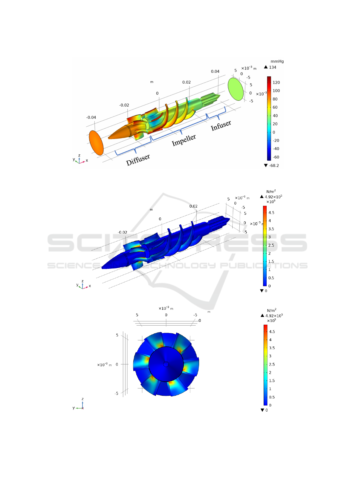
Figure 2: Pressure field for ω = 10500 rpm (clockwise) and v = 1.00 m/s (−x direction).
Figure 3: Von Mises stress on the UHMW-PE material for ω = 10500 rpm and v = 0.25 m/s (isometric view).
Figure 4: Von Mises stress on the UHMW-PE material for ω = 10500 rpm and v = 0.25 m/s (ZY view).
BIODEVICES 2022 - 15th International Conference on Biomedical Electronics and Devices
146

Table 2: Results of the structural simulations for the five selected polymers with ω = 10500 rpm of an impeller with a central
shaft, and different v.
v
Material
t σ
i
p d
M
ε
V
σ
Y
/σ
i
(m/s) (s) (MPa) (MPa) (µm) (×10
−6
)
1.00
Tecapeek 0.0 0.77245 0.52748 0.39591 72.226 151
PC 3.9 0.66055 0.38443 1.2830 144.97 90
PMMA 4.0 0.65195 0.37385 1.8557 217.06 47
PP 4.0 0.73668 0.48078 1.9395 157.95 47
UHMW-PE 2.9 0.85477 0.64944 4.1345 258.31 25
0.75
Tecapeek 0.0 0.75024 0.51608 0.34470 70.236 155
PC 3.9 0.63450 0.43873 1.2281 137.70 94
PMMA 4.0 0.63072 0.42561 1.7783 206.36 49
PP 3.9 0.71975 0.51334 1.8243 154.66 48
UHMW-PE 1.8 0.79739 0.61806 3.8020 233.58 27
0.50
Tecapeek 4.0 0.74566 0.63792 0.79691 67.379 156
PC 2.9 0.81767 0.53219 1.5614 179.64 73
PMMA 2.0 0.79258 0.53728 2.2634 249.68 39
PP 3.0 0.83444 0.72343 2.3327 168.74 41
UHMW-PE 3.6 0.84565 0.89118 4.8891 243.75 26
0.25
Tecapeek 2.9 0.82486 0.75352 0.92138 74.960 141
PC 4.0 0.89698 0.67423 1.8104 186.91 66
PMMA 3.0 0.88899 0.65058 2.6198 281.05 34
PP 3.9 0.95103 0.88347 2.7190 193.00 36
UHMW-PE 2.8 0.99362 1.0715 5.7153 286.49 22
Subsequently, it was determined that the unit volu-
metric deformation (ε
V
) represents a negligible value
for practical purposes, this is because its value has
an order of magnitude between 10
−5
and 10
−4
. Ad-
ditionally, it was found that the order of magnitud
for the maximum displacement (d
M
) is also negiglible
since it is around µm.
During research development, a limit safety factor
of 10 was established represented by the ratio σ
Y
/σ
i
evidenced in table 2. From this factor it was deter-
mined that the following biocompatible polymers are
candidates, from the structural point of view, for the
manufacture of the impeller:
1. TECAPEEK: Polyetheretherketone
2. PC: Polycarbonate
3. PMMA: Polymethyl Methacrylate
4. PP: Polypropylene
5. UHMW-PE: Ultra High Molecular Weight
Polyethylene
Finally, each of these materials has a version for
industrial use and another for medical grade, so a
careful selection of the material with which physical
tests will be implemented is required. In addition, it is
recommended that the experimental tests carried out
Study of Polymers for the Implementation of an Axial Impeller with a Central Shaft in a Ventricular Assist Device
147

should include the determination of the mechanical
properties obtained from the datasheets, to contrast
that information with the one provided by the manu-
facturer.
ACKNOWLEDGEMENTS
The group of researchers thanks the Vicerector
´
ıa de
Investigaci
´
on y Extensi
´
on (VIE) of the Instituto Tec-
nol
´
ogico de Costa Rica for the support provided.
REFERENCES
Anderson, J. (2012). Polymer science: a comprehensive
reference. Amsterdam. Oxford, Waltham: Elsevier.
Araya-Luna, D. (2012). Modelado de la interacci
´
on del flu-
ido sangu
´
ıneo sometido a presi
´
on puls
´
atil en la uni
´
on
de un conducto arterial y un conducto r
´
ıgido (p. 140).
Campus (2020). Cyrolite Med 2 PMMA. [Online].
Available: https://www.campusplastics.com/campus/
es/datasheet/CYROLITE%C2%AE+Med+2/R%C3%
B6hm+GmbH/21/c535b7c0.
Claver
´
ıa, J. and Pu
´
ertolas, J. A. (2011). Implantes
biom
´
edicos. Master’s thesis.
Ensinger (2017a). Chirulen 1020 UHMW-PE. [Online].
Available: https://www.mcam.com/na-en/products/
meditechr-life-science-grade/implantable-polymers/
?r=1#c32789.
Ensinger (2017b). Tecapro MT Black
PP. [Online]. Available: https://www.
ensingerplastics.com/es-br/semielaborados/plastico/
pp-de-grado-medico-tecapro-mt-black.
Ensinger (2020). Tecapeek MT Classix white
PEEK. [Online]. Available: https://www.
ensingerplastics.com/es-br/semielaborados/plastico/
peek-de-grado-medico-tecapeek-mt-classixtm-white-.
Farhat, C. and Lesoinne, M. (2000). Two efficient staggered
algorithms for the serial and parallel solution of three-
dimensional nonlinear transient aeroelastic problems.
Computer methods in applied mechanics and engi-
neering, 182(3-4):499–515.
FDA (2018). Medical device overview. [Online]. Available:
https://www.fda.gov/industry/regulated-products/
medical-device-overview.
James, G. M. (2004). Mechanic of Materials, Sixth Edition.
Thomson Learning.
Matarneh, R., Sotnik, S., and Lyashenko, V. (2018). Poly-
mers in cardiovascular surgery.
Mayorga-Espinoza, C. (2018). Determinaci
´
on computa-
cional del comportamiento fluido-estructura de un im-
pulsor en flujo sangu
´
ıneo. Master’s thesis.
Mu
˜
noz-P
´
erez, J. (2021). Determinaci
´
on computacional de
la fatiga en un impulsor axial sin eje central en flujo
sangu
´
ıneo. Master’s thesis.
Ortiz, G. (2017). Modelo de un nuevo concepto de impulsor
para la aplicaci
´
on en bombas de sangre. PhD thesis.
Ortiz-Le
´
on, G., Araya-Luna, D., and V
´
ılchez-Monge, M.
(2014). Revisi
´
on de modelos te
´
oricos de la din
´
amica
de fluidos asociada al flujo de sangre. Revista Tec-
nolog
´
ıa en Marcha, 27(1):66–76.
Ortiz-Le
´
on, G., Coto-Cort
´
es, A., V
´
ılchez-Monge, M.,
Salazar, C., Campos, G., Varela, F., Araya-Luna,
D. E., Li-Huang, L. A., and Montero-Rodr
´
ıguez, J. J.
(2012). Estudio exploratorio para el desarrollo de un
dispositivo de asistencia card
´
ıaca.
Park, K., Felippa, C., and DeRuntz, J. (1977). Stabilization
of staggered solution procedures for fluid-structure in-
teraction analysis. Computational methods for fluid-
structure interaction problems, 26(94-124):51.
Pedro, J. C. and Sibanda, P. (2012). An algorithm for the
strong-coupling of the fluid-structure interaction us-
ing a staggered approach. International Scholarly Re-
search Notices, 2012.
Reul, H. M. and Akdis, M. (2000). Blood pumps for circu-
latory support. Perfusion, 15(4):295–311.
Rosler, J., Harders, H., and Baker, M. (2007). Mechanical
behaviour of engineering materials, 1st edition, vol-
ume 3. Berlin et al.: Springer-Verlag.
Rugonyi, S. and Bathe, K.-J. (2001). On finite element anal-
ysis of fluid flows fully coupled with structural inter-
actions. CMES- Computer Modeling in Engineering
and Sciences, 2(2):195–212.
Sabic (2020). Lexan Healthcare Resin HPS6 PC. [On-
line]. Available: https://www.sabic.com/en/products/
polymers/polycarbonate-pc/lexan-healthcare-resin.
Song, X., Throckmorton, A. L., Untaroiu, A., Patel, S., Al-
laire, P. E., Wood, H. G., and Olsen, D. B. (2003). Ax-
ial flow blood pumps. ASAIO journal, 49:355–364.
Tchantchaleishvili, V., Sagebin, F., Ross, R. E., Hallinan,
W., Schwarz, K. Q., and Massey, H. T. (2014). Evalu-
ation and treatment of pump thrombosis and hemoly-
sis. Annals of cardiothoracic surgery, 3(5):490.
Teo, A. J., Mishra, A., Park, I., Kim, Y.-J., Park, W.-
T., and Yoon, Y.-J. (2016). Polymeric biomateri-
als for medical implants and devices. ACS Bioma-
terials Science & Engineering, 2(4):454–472. doi:
10.1021/acsbiomaterials.5b00429.
Ugural, A. C. and Fenster, S. K. (2011). Advanced me-
chanics of materials and applied elasticity, 5th edi-
tion. Pearson Education.
BIODEVICES 2022 - 15th International Conference on Biomedical Electronics and Devices
148
