
A Model-based System Engineering Plugin for Safety Architecture
Pattern Synthesis
Yuri Gil Dantas
1
, Tiziano Munaro
1
, Carmen Carlan
1
, Vivek Nigam
2
, Simon Barner
1
, Shiqing Fan
2
,
Alexander Pretschner
1, 3
, Ulrich Sch
¨
opp
1
and Sergey Tverdyshev
2
1
fortiss GmbH, Munich, Germany
2
Huawei Technologies D
¨
usseldorf GmbH, D
¨
usseldorf, Germany
3
Technische Universit
¨
at M
¨
unchen, Munich, Germany
fi
Keywords:
Model-based System Engineering, Safety Architecture Patterns, Automation, Tooling.
Abstract:
Safety architecture patterns are abstract representations to address faults in the system architecture. In the
current state of practice, the decision of which safety architecture pattern to deploy and where in the system
architecture is carried out manually by a safety expert. This decision may be time consuming or even lead
to human errors. This paper presents Safety Pattern Synthesis, a tool for automating the recommendation of
safety architecture patterns during the design of safety-critical systems: 1) Safety Pattern Synthesis recom-
mends patterns to address faults in the system architecture (possibly resulting in more than one architectural
solution), 2) the user selects the system architecture with patterns based on, e.g., the criteria provided by Safety
Pattern Synthesis, and 3) Safety Pattern Synthesis provides certain requirements that shall be considered in the
overall safety engineering process. The proposed tool has been implemented as a plugin in the model-based
system engineering tool called AutoFOCUS3. Safety Pattern Synthesis is implemented in Java while using
a logic-programming engine as a backend to reason about the safety of the system architecture. This paper
provides implementation details about Safety Pattern Synthesis and its applicability in an industrial case study
taken from the automotive domain.
1 INTRODUCTION
Safety architecture patterns, such as the Homoge-
neous Duplex or the Triple Modular Redundancy pat-
terns, are deployed to avoid harm due to faults trig-
gering failures, such as erroneous function or loss
of function (Avizienis et al., 2004). An advan-
tage of making use of such patterns in practice is
that their goal and development are well understood,
and even recommended by standards (ISO26262,
2018)(IEC61508, 2010).
In the current state of practice, the decision of
which safety architecture pattern to deploy in a given
system architecture is done with limited computer-
aided support. Currently, an expert (e.g., a safety en-
gineer) determines which pattern to deploy and where
by carrying out a manual safety analysis. As the
complexity of systems grows, it becomes challenging
for experts to make these decisions due to, e.g., time
consuming and human error issues. Moreover, since
these decisions are normally made in early stages of
design, potential errors or sub-optimal designs may
result in high development delays and costs.
Current safety-critical systems are character-
ized by an ever-increasing number of highly inter-
dependant requirements, functions and subsystems.
The safe integration of critical and non-critical com-
ponents onto a shared execution platform is very im-
portant to enable the certification of such systems.
While integration platforms such as time-space par-
titioning hypervisors or dedicated hardware units that
support the segregation of critical tasks are available
today, such constitute a large configuration space that
adds additional complexity to determine an architec-
ture configuration that satisfies all constraints (in par-
ticular in terms of safety and performance).
The inherent abstraction introduced by Model-
Based System Engineering (MBSE) has the poten-
tial to meet these challenges, as it has been shown
in e.g., an model based engineering approach for
mixed-criticality systems (Barner et al., 2017), the
model-based architecture exploration approach intro-
duced by Eder et al. (Eder et al., 2018b)(Eder et al.,
2018a)(Eder et al., 2020), or in the approaches by
36
Dantas, Y., Munaro, T., Carlan, C., Nigam, V., Barner, S., Fan, S., Pretschner, A., Schöpp, U. and Tverdyshev, S.
A Model-based System Engineering Plugin for Safety Architecture Pattern Synthesis.
DOI: 10.5220/0010831700003119
In Proceedings of the 10th International Conference on Model-Driven Engineering and Software Development (MODELSWARD 2022), pages 36-47
ISBN: 978-989-758-550-0; ISSN: 2184-4348
Copyright
c
2022 by SCITEPRESS – Science and Technology Publications, Lda. All rights reserved

(Amorim et al., 2017)(Martin et al., 2020) that use
MBSE to address the complexity of safety architec-
ture design using architecture patterns. A key lim-
itation of the existing approaches for safety archi-
tecture patterns is that it does not provide the type
of automation successfully applied in other develop-
ment phases, such as in optimizing deployment strate-
gies (Eder et al., 2018b).
Our goal is to provide safety engineers with
computer-aided support for selecting safety architec-
ture patterns in an automated fashion. To this end,
we have developed a plugin within the MBSE tool
AutoFOCUS3 (Aravantinos et al., 2015) to enable the
model-driven approach using safety architecture pat-
terns. We refer to the developed plugin as Safety
Pattern Synthesis. Safety Pattern Synthesis relies on
MBSE practices to automatically recommend safety
architecture patterns for tolerating faults in the system
architecture. The intended outcome of Safety Pattern
Synthesis is to reduce the effort from safety engineers
during a safety analysis, in particular by assisting with
the selection of patterns to ensure the required func-
tional safety of the system architecture. To the best
of our knowledge, Safety Pattern Synthesis is the first
MBSE tool that enables the automated recommenda-
tion of safety architecture patterns.
The development of Safety Pattern Synthesis has
been motivated by concrete use-cases provided by
our industry partner. In this paper, we illustrate how
Safety Pattern Synthesis has been used for the devel-
opment of safe Highway Pilot (HWP) features, such
as Adaptive Cruise Control (ACC) and Emergency
Brake (EB) functions.
The remainder of this paper is structured as fol-
lows: Section 2 presents some background informa-
tion to help the reader to understand the results pre-
sented in the paper. Section 3 describes Safety Pattern
Synthesis, including its architecture and implementa-
tion details. Safety Pattern Synthesis is validated in
Section 4 using an industry use-case. Finally, we con-
clude the paper by pointing out to related and future
work in Sections 5 and 6.
2 BACKGROUND
2.1 Model-based Engineering in
AutoFOCUS3
AutoFOCUS3 (AF3) is a model-based open source
tool and research platform for safety-critical embed-
ded systems (fortiss GmbH, 2020). AF3 builds on
the Eclipse platform and supports the design, devel-
opment and validation of safety-critical embedded
systems in many development phases, including ar-
chitecture design, implementation, and hardware and
software integration.
The tool’s metamodel (Aravantinos et al.,
2015)(Barner et al., 2018) provides multiple view-
points to describe the different aspects of the system
under design. The logical architecture represents an
implementation-agnostic specification of the system’s
behaviour. The technical viewpoint includes a series
of models. The task and partition architectures
represent the hardware-independent interaction of
software tasks and their aggregation into partitions,
and the platform architecture describes the system’s
hardware including its properties and topology.
Finally, the distinct models are linked by means of
allocations, defining, e.g., the deployment of tasks to
hardware units.
2.2 Safety Concepts
We briefly review some basic safety concepts to set
the terminology used in the remainder of the paper.
The definition of the safety concepts described below
are mainly taken from (Avizienis et al., 2004).
A hazard is a situation that can cause harm to
users or businesses. A failure is an event that when
occurs results in a deviation of the expected behavior
of a function. An error is a deviation of the expected
system behavior. A fault is the hypothesized cause
of an error. A failure triggered by a fault may lead
to a hazard. Normally, failures are associated with a
set of predefined Guidewords that characterize intu-
itively the semantics of such failures. Examples of
Guidewords are loss and erroneous that denote, re-
spectively, a failure due to the loss of a function, i.e.,
a function not operating whatsoever, and a failure due
to an erroneous function behavior, e.g., a function not
computing correctly some output value. This paper
refers to hazards, faults, and failures as safety ele-
ments. A component is a part of a system that im-
plements a function and consists of software units or
hardware parts. Components may be assigned to an
Automotive Safety Integrity Level (ASIL), i.e., the
level of safety assurance required ranging among QM,
A, B, C, D, where D is the highest assurance level.
A safety architecture pattern (safety pattern for
short) is an architectural solution for tolerating faults
in the system architecture. A fault detection pattern
deactivates the system in the presence of a failure
(triggered by a fault) by either transitioning the sys-
tem to a safe state (e.g., informing the driver to take
over the vehicle control) or shutting down the system.
A fault tolerant pattern ensures that the system will
A Model-based System Engineering Plugin for Safety Architecture Pattern Synthesis
37

continue to operate in the presence of a failure by pro-
viding a redundant component to take over. Fault tol-
erant patterns improve the availability of the system
given the redundant component. A fault tolerant pat-
tern may also transition the system to a safe state or
shutdown the system in the presence of a failure in the
redundant component.
Examples of safety patterns are Homogeneous
Duplex, Heterogeneous Duplex, Triple Modular Re-
dundancy, Simplex Architecture, Acceptance Voting,
and Monitor Actuator (Armoush, 2010)(Preschern
et al., 2013b)(Biondi et al., 2020)(Bak et al., 2009).
Homogeneous Duplex pattern is a fault tolerant
pattern that addresses hardware faults by duplicating
the primary hardware component. Similarly, Hetero-
geneous Duplex pattern is a fault tolerant pattern that
also addresses hardware faults by duplicating the pri-
mary hardware component. However, the primary
and the redundant components shall be designed and
implemented independently from each other. Hetero-
geneous Duplex pattern may also address software
faults as long as the software running in redundant
component is implemented using a different design.
Triple Modular Redundancy pattern is a fault toler-
ant pattern that addresses hardware faults by tripli-
cating the primary hardware component. Simplex Ar-
chitecture pattern is a fault tolerant pattern that ad-
dresses software faults by providing a simple and re-
liable version of the primary component. Acceptance
Voting pattern is a fault tolerant pattern that addresses
software faults by providing diverse redundancy im-
plementations of the primary software component.
Monitor Actuator pattern is a fault detection pattern
mainly known for addressing hardware faults, but it
can also address software faults through the use of
plausibility checks.
2.3 SafPat (Backend)
A framework called SAFPAT (Dantas et al., 2020)
has been recently proposed for automating the rec-
ommendation of safety patterns. SAFPAT receives as
input the designed system architecture and safety el-
ements. SAFPAT performs changes in the system ar-
chitecture by adding safety patterns in an automated
fashion. SAFPAT has been implemented in DLV, a
logic programming language based on the Answer Set
Programming paradigm (Leone et al., 2006). SAFPAT
is the backend of the plugin proposed by this paper.
SAFPAT consists of a domain-specific language
(DSL) for embedded systems and reasoning princi-
ples that enable the automated recommendation of
which patterns and where in the system architecture
they shall be deployed. These reasoning principles
are automated by the DLV engine.
DSL. The DSL enables the specification of archi-
tectural elements (e.g., components and channels),
safety elements (e.g., faults), and safety patterns.
SAFPAT currently supports the following safety pat-
terns: Acceptance Voting, Homogeneous Duplex, Het-
erogeneous Duplex, Monitor-Actuator, Simplex Ar-
chitecture, and Triple Modular Redundancy.
Table 1 illustrates how SAFPAT provides
semantically-rich description of safety patterns.
To this end, we provide an example of a template
which is similar to pattern templates appearing in
the literature (Armoush, 2010)(Sljivo et al., 2020).
We instantiate the template with the Homogeneous
Duplex pattern. Specifically, Table 1 provides a high-
level description of the pattern and its specification in
SAFPAT. The assumptions described in the table are
not meant to be comprehensive. By assumptions, we
refer to requirements that shall be satisfied to ensure
the safety patterns work as intended.
Reasoning Principles. SAFPAT provides means to
reason about the safety of the system architecture,
in particular to recommend safety patterns. SAF-
PAT consists of reasoning principle rules to deter-
mine when (a) a failure is avoided, (b) a fault is toler-
ated, and (c) a hazard is controlled (a.k.a. mitigated).
Specifically, (a) a failure is avoided if a suitable safety
pattern is deployed, (b) a fault is tolerated if all fail-
ures triggered by that fault are avoided, and (c) a haz-
ard is controlled if the fault triggering failures leading
to that hazard is tolerated.
Whenever a safety pattern is recommended (see
next paragraph), the rules for (a), (b), and (c) apply
to infer which hazards have been controlled. SAFPAT
only outputs architectural solutions where all hazards
(received as input) have been controlled.
SAFPAT specifies reasoning rules for automating
the recommendation of safety patterns. These rules
specify conditions for when a particular pattern can
be recommended to avoid failures triggered by faults.
The following are the main conditions specified
by SAFPAT when recommending the Homogeneous
Duplex pattern (homogeneousDuplex):
• there is a fault FT in the hardware component PR
that triggers a failure FL leading to hazard HZ;
• homogeneousDuplex is suitable for addressing
hardware faults;
• homogeneousDuplex is suitable for avoiding FL’s
type of failure (i.e., erroneous or loss);
• homogeneousDuplex is suitable for addressing
the ASIL of HZ. Since the Homogeneous Duplex
pattern is suitable for ASIL D, it is also suitable
for lower levels, i.e., ASIL A, B and C.
• the safety mechanism type (i.e., fault tolerant or
MODELSWARD 2022 - 10th International Conference on Model-Driven Engineering and Software Development
38
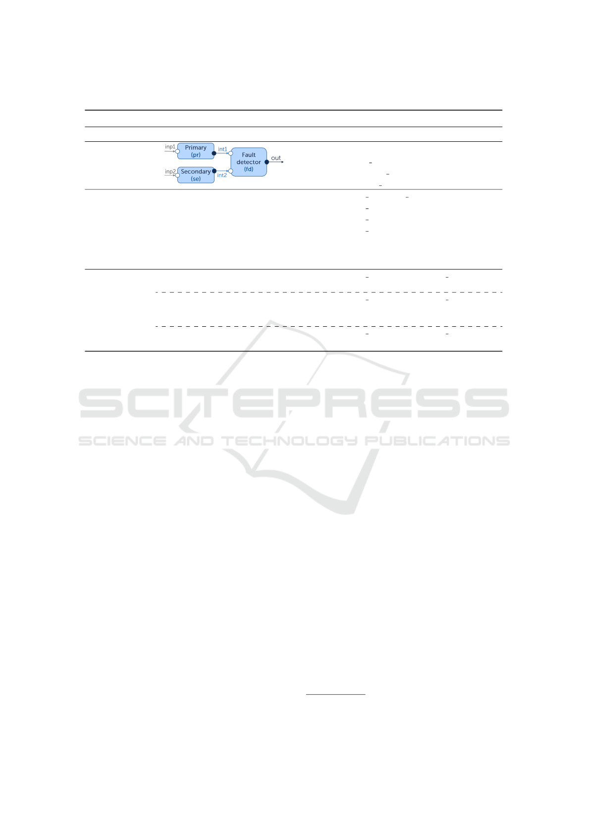
Table 1: Instantiation of the Homogeneous Duplex pattern. The assumptions are not meant to be comprehensive.
Description SAFPAT Specification
Pattern name Homogeneous Duplex Pattern NAME=homogeneousDuplex;
Structure
COMPONENTS=[pr,se,fd];
INPUT CH=[inp1,inp2];
INTERNAL CH=[int1,int2];
OUTPUT CH=[out];
Intent This pattern is fault tolerant, suitable for
both addressing high criticality hazards
(ASIL D) (Armoush, 2010) and tolerating
hardware faults.
TYPE PAT=fault tolerant;
TYPE ASIL=d;
TYPE CP=[hardware];
TYPE FAIL=[erroneous,loss];
Problem ad-
dressed
This pattern tolerates faults by avoiding
failures of type erroneous or loss.
Assumptions
(requirements)
The primary and the secondary compo-
nents shall be identical.
TYPE ASSUMPTION=are identical;
COMPONENTS=[pr,se];
The primary and the secondary compo-
nents shall be allocated to different hard-
ware units.
TYPE ASSUMPTION=are decoupled;
COMPONENTS=[pr,se];
The fault detector shall be verified. TYPE ASSUMPTION=are verified;
COMPONENTS=[fd];
detection) of heterogeneousDuplex matches the
type of the safety mechanism chosen by the user.
SAFPAT may provide multiple architectural solu-
tions as output, with different safety patterns for each
solution. For example, possible patterns for tolerat-
ing a software fault include the use of either the Ac-
ceptance Voting pattern or the Heterogeneous Duplex
pattern. The user may select the most suitable system
architecture with patterns based on some criteria such
as the ones described in Section 3.1.
SAFPAT also specifies requirements for ensuring
safety integrity w.r.t. the allocation of software com-
ponents to hardware components. For example, con-
sider an allocation of a software component SW1 into
a hardware component HW1. SAFPAT’s reasoning
rules check whether the ASIL of SW1 is higher than
the ASIL of HW1. If this condition is true, SAFPAT
provides a requirement to allocate SW1 to a hardware
component with the same ASIL of SW1.
We refer the interested reader to (Dantas et al.,
2020) for the detailed description about SAFPAT, in-
cluding its reasoning principles rules.
3 SAFETY PATTERN SYNTHESIS
Safety Pattern Synthesis is a plugin of the model-
based system engineering tool AutoFOCUS (AF3)
for recommending safety patterns. Figure 1 depicts
the artifacts that are used by Safety Pattern Synthesis
(system architecture and safety elements) and which
artifacts are produced (system architecture with pat-
terns and requirements).
• System Architecture: This artifact consists of
the designed system architecture. The designed
architecture includes the task and platform archi-
tecture for the system, and the allocation of tasks
to hardware units. In addition, architectural com-
ponents (tasks or hardware units) may be assigned
to the ASIL that such components shall be imple-
mented. We assume that the system architecture
is designed following an model-based engineer-
ing approach, e.g., developed in AF3.
• Safety Elements: This artifact consists of the
results from a safety analysis
1
carried out by a
safety engineer on the designed system architec-
ture. This consists of hazards, faults and fail-
ures. Faults are associated with architectural com-
ponents (tasks or hardware units) in the system
architecture. As shown in Section 3.1, we have
developed a wizard for defining these safety ele-
ments in AF3.
• Safety Pattern Synthesis: The developed plugin
recommends safety architecture patterns based on
the system architecture and safety elements. The
reasoning on which pattern to select and where
to place the selected pattern in the architecture is
1
In our example described in Section 4, the safety anal-
ysis was carried out using the STPA method
A Model-based System Engineering Plugin for Safety Architecture Pattern Synthesis
39

System architecture
architecture
allocations
ASIL of components
Safety Pattern Synthesis
1
System architecture with patterns
1..n
Requirements
1..m
Safety elements
hazards
faults
failures
1..t
CREATED WITH YUML
Figure 1: Safety Pattern Synthesis: Simplified diagram. Gray boxes are artifacts received as input or generated for output.
performed with the help of SAFPAT (described in
Section 2.3). Safety Pattern Synthesis generates
the following artifacts:
– System Architecture with Patterns: Safety
Pattern Synthesis provides a list of modified
AF3 architecture models with patterns. For ex-
ample, possible solutions for tolerating a hard-
ware fault in the platform architecture include
the use of either the Homogeneous Duplex pat-
tern or the Triplex Modular Redundancy pat-
tern. The user of Safety Pattern Synthesis shall
then select the most suitable architecture for the
system. Section 3.1 provides some criteria to
assist the user in selecting the architecture.
– Requirements: Safety Pattern Synthesis pro-
vides requirements that shall be implemented
during system development. In particular,
Safety Pattern Synthesis provides requirements
for (a) the recommended safety patterns, i.e.,
requirements to ensure that the recommended
safety patterns work as intended (examples of
such requirements are described in Table 1),
and (b) safety integrity, e.g., to ensure that the
allocation of tasks to hardware units complies
with the ASIL assigned to tasks.
The following section describes the high-level ar-
chitecture of Safety Pattern Synthesis, including im-
plementation details and how an user interacts with
Safety Pattern Synthesis.
3.1 High-level Architecture
The architecture of Safety Pattern Synthesis is illus-
trated by Figure 2. Safety Pattern Synthesis has been
developed, as part of the AF3 framework, in Java
(frontend) and DLV (backend), and currently works
under Linux and Windows.
Safety Pattern Synthesis receives the input arti-
facts described above. The architecture of Safety Pat-
tern Synthesis consists of the following components:
• Safety Elements Wizard: This component pro-
vides a wizard to enable users to define the safety
elements obtained from a safety analysis. The
component requires an interface to the designed
system architecture so that it can assign faults to
components (i.e., tasks or hardware units). Fig-
ure 4 illustrates our wizard to define safety ele-
ments. Firstly, the user defines a hazard consist-
ing of the hazard’s description and its ASIL. Sec-
ondly, the user selects the (possibly) faulty com-
ponents (either tasks for software faults or ECUs
for hardware faults). Thirdly, for each selected
fault, the user defines the type of failure (either
erroneous or loss) triggered by the fault.
2
Finally,
the user defines which type of safety mechanism
(either fault detection of fault tolerant) shall toler-
ate the identified faults, and consequently address
the identified hazard.
• Model-to-Model Transformation from AF3 to
SAFPAT: To make use of SAFPAT for safety pat-
tern recommendation, we implemented a model-
to-model transformation from AF3 (which is im-
plemented in Java) to SAFPAT (which is imple-
mented in DLV). We transform AF3 system archi-
tecture models and safety element models (speci-
fied in the wizard) to SAFPAT models. Figure 3 il-
lustrates a model-to-model transformation from a
task architecture modeled in AF3 to SAFPAT. The
translation is implemented with the help of the
EmbASP framework (EmbASP, 2018). EmbASP
enables the Java representation of predicates that
are specified in a DLV program. We represent in
Java each relevant predicate that can be used in the
DSL of SafPat. This includes the representation of
architectural elements designed in AF3 and safety
elements. Technically, we represent each relevant
predicate by a Java class.
• SafPat: This component reasons about the safety
of the system architecture. Explained in Sec-
tion 2.3, this component is the backend of Safety
2
Currently, Safety Pattern Synthesis supports two
Guidewords, erroneous and loss, which are most commonly
used in methodologies such as HAZOP. We plan in the fu-
ture to incorporate other Guidewords such as early and late.
MODELSWARD 2022 - 10th International Conference on Model-Driven Engineering and Software Development
40
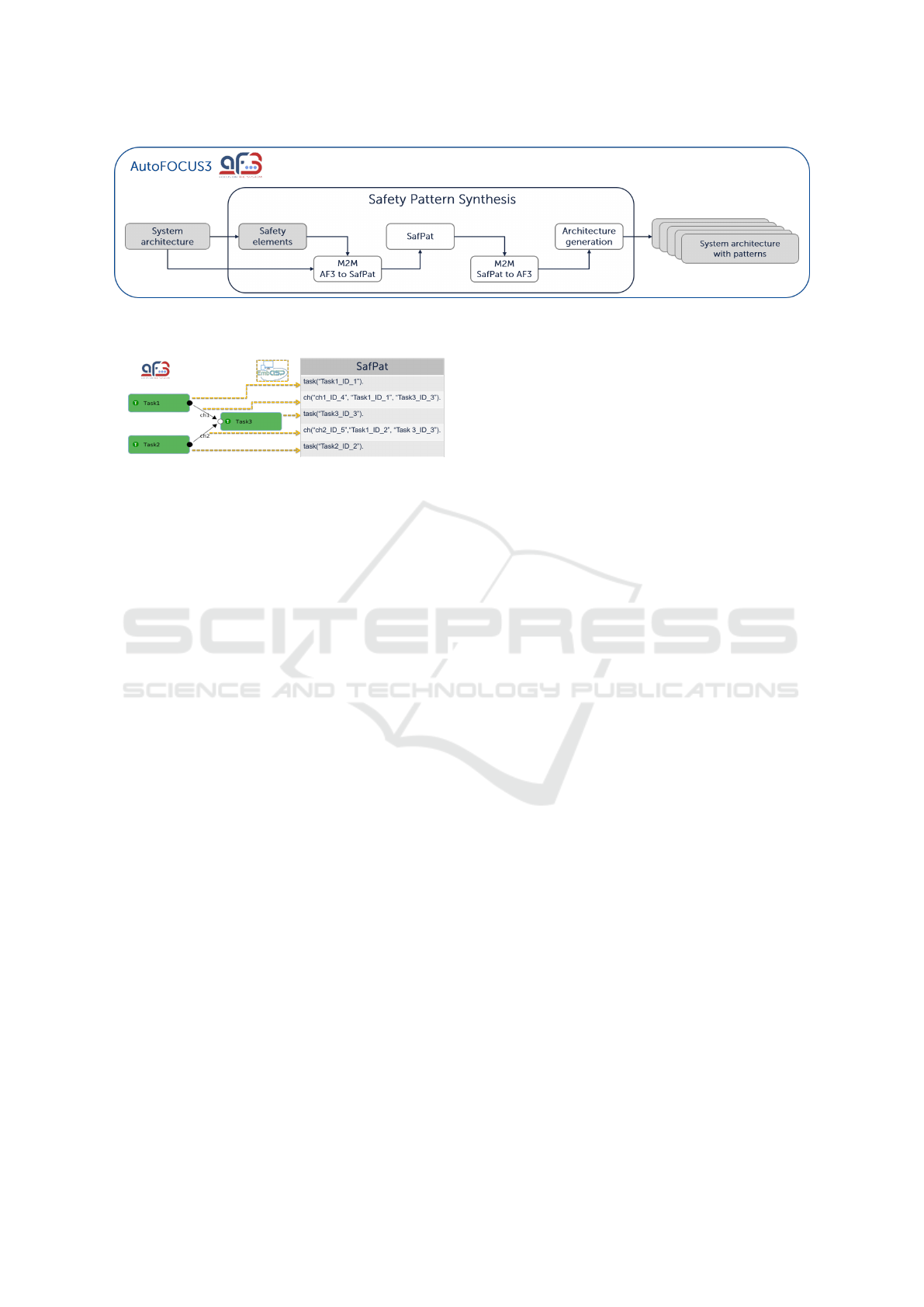
Figure 2: Architecture of Safety Pattern Synthesis. Gray boxes are artifacts either received as input or generated for output.
Safety Pattern Synthesis generates requirements for each System architecture with patterns (output artifact).
Figure 3: Illustration of a model-to-model transformation
from a task architecture modeled in AF3 (left side) to SAF-
PAT (right side) with the help of EmbASP (illustrated by the
yellow arrows). The IDs of tasks and channels in the AF3
model are omitted in the figure.
Pattern Synthesis. Once the representation is fully
realized, Safety Pattern Synthesis (via EmbASP)
invokes SafPat by sending the translated system
architecture and safety elements. Based on the
specified reasoning principles, SAFPAT attempts
to deploy safety patterns wherever they are appli-
cable to tolerate faults. SAFPAT may return a list
of modified architectures with patterns. SAFPAT
also outputs requirements (a.k.a. assumptions).
• Model-to-Model Transformation from SAFPAT
to AF3: This component translates the results
obtained from SAFPAT to AF3 models enabling
the representation of the system architecture with
safety patterns in AF3. The translation is obtained
with the help of the EmbASP framework that en-
ables the parsing of DLV facts to Java. The trans-
lation is similar to the one illustrated in Figure 3
(but in reverse order, i.e., from SAFPAT to AF3).
To identify the changes in the system architec-
ture, SAFPAT makes explicit all the changes made
in the architecture by using a prefixing scheme.
This prefixing scheme is used for new channels
and new components, and for channels (from the
baseline architecture) to be removed.
• Architecture Generation: This component pro-
vides a list of system architectures with safety pat-
terns represented as AF3 models to be selected by
the user. This component implements a wizard for
visualizing the solutions obtained from SAFPAT,
including a number of criteria to assist the user
in selecting the most suitable architecture for sys-
tem. Currently, Safety Pattern Synthesis supports
the following criteria:
1. Number of new components describes the
number of diverse application components re-
quired by the safety pattern. For example, Het-
erogeneous Duplex pattern requires one redun-
dant diverse component. The user can make a
decision based on, e.g., the number of applica-
tion components to be developed.
2. Number of replica components describes the
number of redundant components required by
the safety pattern. A user can make a decision
based on, e.g., the number of replica that need
to be introduced.
3. Number of pattern support components de-
scribes the number of non-application compo-
nents required by the safety pattern. Examples
of non-application components are the fault de-
tector of the Heterogeneous Duplex pattern and
the monitor of the Simplex Architecture pat-
tern. A user can make a decision based on, e.g.,
the overhead introduced by the safety pattern
and on the number of pattern support compo-
nents to be developed.
4. Simplified (a.k.a. degraded) describes
whether the modified architecture with patterns
contains a simplified application component.
For example, the redundant component of the
Simplex Architecture pattern is a simpler ver-
sion of the primary component. A user can
make a decision based on, e.g., the minimum
available fidelity level of components.
Safety Pattern Synthesis provides two wizards for
visualizing the architectural solutions with pat-
terns. One wizard with a spider chart view for
showing the criteria based on the recommended
patterns. The other wizard implements a table
view that provides more detail, in addition to cri-
teria, such as which safety pattern was recom-
mended and additional requirements. For exam-
ple, the highlighted solution in Figure 5 deploys
one instance of the Heterogeneous Duplex pattern
A Model-based System Engineering Plugin for Safety Architecture Pattern Synthesis
41

(htd) and one instance of the Homogeneous Du-
plex pattern (hmd). Once the user has chosen the
system architecture, the user selects and exports
an architecture by clicking on the “Select” and
“Export” buttons, respectively.
The exported architectural solution (System ar-
chitecture with patterns) will be shown the mod-
elling view of AF3. An example of the exported solu-
tion is presented in Section 4.2.
Remark: Figure 5 shows the additional requirements
for ensuring (a) the recommended safety pattern work
as intended, and (b) the safety integrity of the system.
The highlighted solution in Figure 5 contains 15 re-
quirements, including the ones for the Homogeneous
Duplex pattern described in the pattern template (see
Table 1). Once an architectural solution has been ex-
ported, the implementation of the additional require-
ments shall be carried during the system development.
3.2 Download
We have built a binary of Safety Pattern Synthesis to
ease the use of the plugin. The binary of Safety Pat-
tern Synthesis can be download here (Safety Pattern
Synthesis, 2021). It also contains a video illustrating
how one can run Safety Pattern Synthesis to select
safety patterns in an automated fashion.
4 CASE STUDY
We consider an industrial use case taken from the au-
tomotive domain. We describe the system architec-
ture and selected safety elements (e.g., faults) that will
serve as input artifacts for Safety Pattern Synthesis.
We then run Safety Pattern Synthesis to recommend
safety patterns for tolerating the identified faults.
4.1 Use Case
System Architecture. We consider an industrial
use-case, namely the Highway Pilot (HWP). The
nominal function of a HWP is predominantly defined
as the longitudinal and lateral control of a vehicle’s
movement up to a given maximum speed to realize a
trajectory under consideration of the limitations given
by the lane, other vehicles, and the ego vehicle itself.
This specification of the system’s nominal func-
tion can be further broken down into functional re-
quirements. The HWP shall
1. Req 1: not cause the ego vehicle to exceed its
maximum velocity,
2. Req 2: keep the ego vehicle either at a set speed
or adapt its speed to a leading vehicle,
3. Req 3: keep the ego vehicle at the center of the
current lane,
4. Req 4: include a stop & go functionality, and
5. Req 5: inform the driver about its status.
As the HWP takes over the complete Dynamic
Driving Task (DDT) as well as Object and Event
Response (OEDR), the system is classified as a
highly safety-critical, ASIL-D rated, level 3 Auto-
mated Driving System (ADS) according to the SAE
J3016 standard (SAEJ3061, 2012)(ISO26262, 2018).
HWP has been designed in AutoFOCUS3 (AF3)
as part of the fortissimo
3
demonstrator platform. The
HWP architecture consisting of both task and plat-
form architectures are illustrated in Figure 6.
The Sensor Data Fusion processes data generated
by a front-mounted sensors to determine the distance
of leading vehicles or obstacles as well as the ego ve-
hicle’s position within the lane. The Adaptive Cruise
Control (ACC) and Lane Keeping Assistance (LKA)
provide longitudinal and lateral control, respectively
– each according to the HWP’s nominal function. The
Emergency Brake (EB) provides longitudinal control
in case a collision with an obstacle in front of the ve-
hicle is deemed unavoidable. Here, the goal is not
collision avoidance, but mitigation. The system is al-
ways active as such situations can arise both during
manual driving as well as due to a fault of the HWP.
The Motion Control coordinates the desired vehicle
states given by the driving functions and controls the
torque applied by the servo steering, and the throttle
position accordingly.
The hardware dedicated to the execution of the
HWP is specified by means of hierarchical platform
architecture models. A simplified version of the plat-
form architecture is illustrated in Figure 6.
Table 2 describes the allocation of task to hard-
ware units, as well as the ASIL requirements for each
component (i.e., the ASIL that each component shall
be implemented).
Safety Elements. For the sake of our evaluation,
we consider the following safety elements that can be
identified from a safety analysis. The identified safety
elements are not meant to be comprehensive.
Table 3 describes the identified hazards HZ1 and
HZ2. We assigned ASIL B to HZ2 as we consider
the exposure of HZ2 as low probability of happening.
These hazards may happen on the occurrence or pres-
ence of failures triggered by the following faults:
3
https://www.fortiss.org/en/research/living-lab/detail/
fortissimo
MODELSWARD 2022 - 10th International Conference on Model-Driven Engineering and Software Development
42
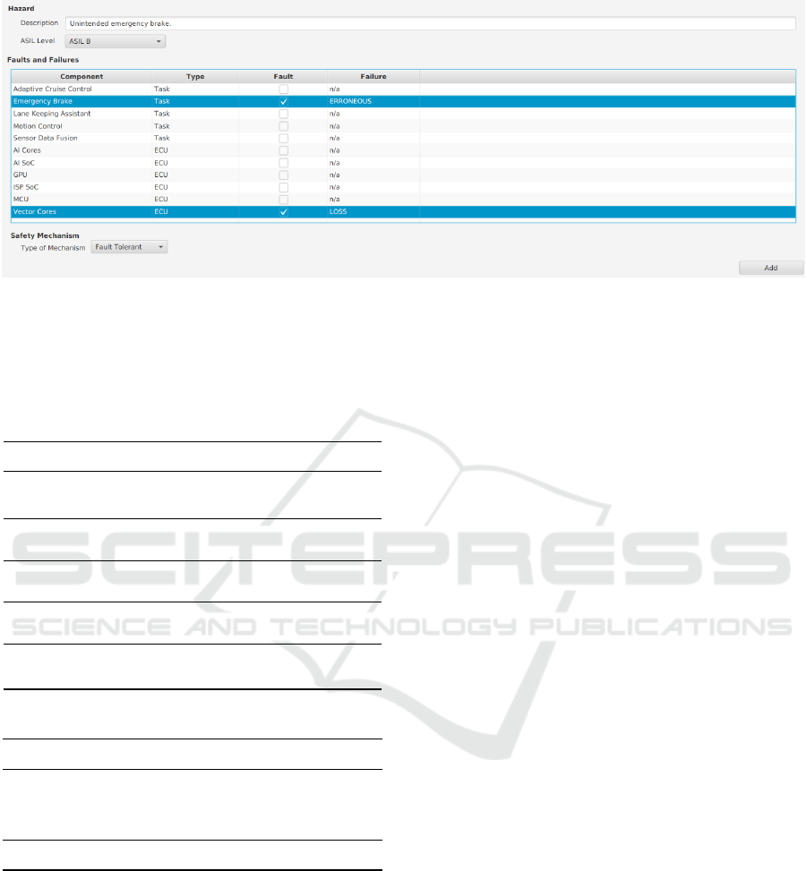
Figure 4: Screenshot of the wizard for defining safety elements.
Table 2: Allocation and ASIL of components. Note that last
allocation does not comply with the safety integrity level
required (i.e., ASIL D task allocated to ASIL B hardware
unit). The intended outcome is to show that Safety Pattern
Synthesis can provide requirements to ensure the safety in-
tegrity w.r.t. allocations.
Task Hardware Unit
Sensor Data Fusion
[ASIL B]
Host SoC (GPU)
[ASIL B]
ACC
[ASIL D]
MCU
[ASIL D]
LKA
[ASIL D]
MCU
[ASIL D]
EB
[ASIL B]
Host SoC (Vector
Cores) [ASIL B]
Motion Control
[ASIL D]
AI SoC
[ASIL B]
Table 3: Identified hazard for the HWP system.
Hazard Description ASIL
HZ1 The vehicle violates the safety
distance to other road users or
objects on the road.
D
HZ2 Unintended emergency brake. B
• FT1: A software fault occurs in the algorithm im-
plemented by the task implementing ACC causes
the provided target deceleration value not be high
enough to reach the safety distance between vehi-
cles. The failure of type erroneous triggered by
fault FT1 may lead to hazard HZ1.
• FT2: A hardware fault occurs in the hardware unit
to which EB is allocated. This causes EB not to
provide the target deceleration needed to avoid a
front-end collision. The failure of type loss trig-
gered by fault FT4 may lead to hazard HZ2.
4.2 Results
Consider the system architecture and the safety ele-
ments described in Section 4.1. We run Safety Pat-
tern Synthesis to determine patterns that can tolerate
the identified faults and address the identified hazards.
Safety Pattern Synthesis recommended twelve so-
lutions for tolerating the identified faults. The recom-
mended safety patterns are described in Table 4. Con-
sidering that both the system architecture has been
loaded, and the identified safety elements have been
annotated to architectural elements, we accomplished
the results depicted in Table 4 with a few clicks only.
As an example, consider the task architecture from
Solution 10 illustrated in Figure 7, where the Het-
erogeneous Duplex pattern is applied to ACC and the
Monitor Actuator pattern is applied to EB. Both ACC
(V2) and Fault Detector tasks are created to toler-
ate the software faults that may be present in ACC
(V1). That is, if one fault is detected in ACC (V1),
the function ACC will continue operating using the
outputs from ACC (V2). This solution contains addi-
tional requirements to be implemented to ensure that
the pattern works as intended such as ACC (V1) and
ACC (V2) tasks shall be developed using different de-
sign, and for safety integrity such as ACC (V2) and
Fault Detector tasks shall be developed using ASIL
D requirements to comply with the safety integrity of
ACC (V1), as shown in Table 2.
The Monitor Actuator task is created to toler-
ate hardware faults of type loss in the hardware unit
where EB is allocated (i.e., Vector Cores). To this end,
the Monitor Actuator task shall implement a timeout
algorithm to detect failures of type loss triggered by
a fault in Vector Cores. This requirement is provided
by Safety Pattern Synthesis to be realized during the
system development.
Safety Pattern Synthesis provides requirements to
ensure safety integrity w.r.t. allocations. Consider the
A Model-based System Engineering Plugin for Safety Architecture Pattern Synthesis
43
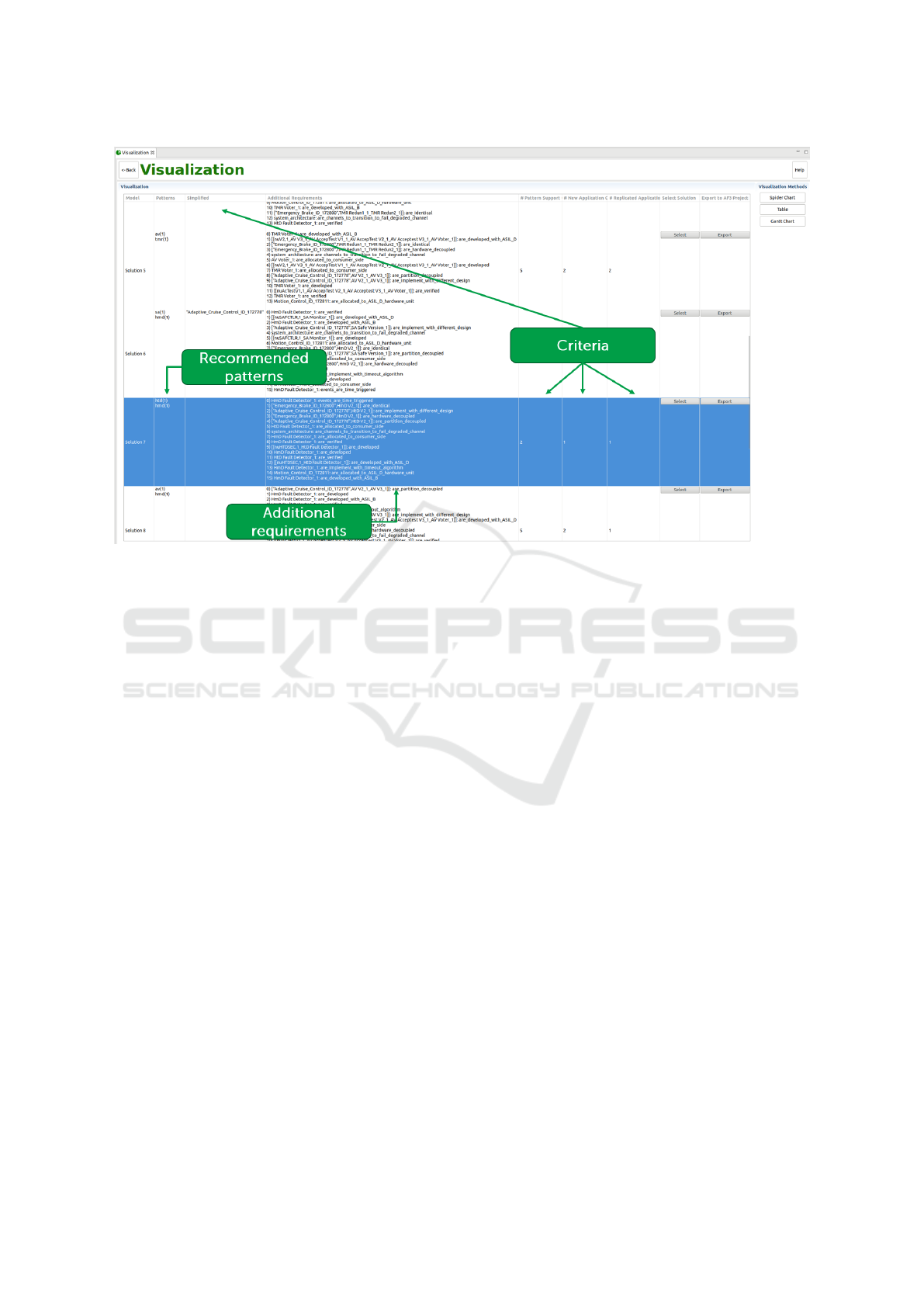
Figure 5: Screenshot of the wizard for visualizing architectural solutions with patterns. It includes the recommended patterns,
the additional requirements to be implemented during the system development, and some criteria to assist the user in selecting
the most suitable architecture for the system.
allocation of the Motion Control [ASIL D] to AI SoC
[ASIL B] in Table 2. This allocation does not comply
with the safety integrity ASIL D given that AI SoC is
ASIL B. Safety Pattern Synthesis provides a require-
ment to ensure the safety integrity, i.e., Motion Con-
trol shall be allocated to an ASIL D hardware unit.
4.3 Discussion
We discuss some issues that are left out of the scope
of this work, but that are important for Safety Pattern
Synthesis deployment in industry.
Handling Potential Design Option Explosion.
Safety Pattern Synthesis may provide a considerably
high number of solutions to be selected by the user,
as shown in Table 4. Currently, Safety Pattern Syn-
thesis provides four criteria (see Section 3.1) to assist
the user with this decision. We are investigating fur-
ther criteria used, for example, by AutoFOCUS3 for
design space exploration (Eder et al., 2020), such as,
the performance overhead caused by safety patterns,
implementation cost, and the hardware resource us-
age required by safety patterns. These criteria can be
used to rank more precisely design options eliminat-
ing non-optimal ones, thus reducing options.
Towards Incremental Development. In this work,
we consider only one development loop. That is, once
safety elements are identified a user can make use
of Safety Pattern Synthesis to deploy safety patterns
into the system architecture. It remains to be investi-
gated how Safety Pattern Synthesis can be extended
to support incremental development where several
loops are involved. For example, consider an architec-
ture with safety patterns, possibly recommended by
Safety Pattern Synthesis, and a new unhandled fault.
Currently Safety Pattern Synthesis would recommend
new safety patterns without modifying the existing
ones. This may not lead to optimal solutions as it does
not exploit synergies between patterns, e.g., a safety
pattern that provide more fault tolerance can subsume
other weaker patterns. It seems possible to use Safety
Pattern Synthesis in a search mechanism procedure
where pattern recommendations are withdrawed by
backtracking and new more more optimized architec-
tures are recommend.
Scalability. Safety Pattern Synthesis reduces the
problem of pattern recommendation to a logical the-
ory (specified by SAFPAT) that is NP-complete in
general. This does not necessary mean that Safety
Pattern Synthesis cannot be used in practice as spe-
cialized engines, such as SMT-solvers, have been
used in industry projects (Eder et al., 2020) for other
MODELSWARD 2022 - 10th International Conference on Model-Driven Engineering and Software Development
44
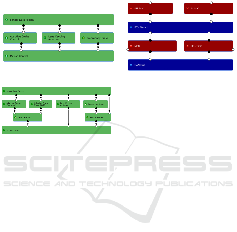
Figure 6: Highway Pilot (HWP): Task (left side) and platform (right side) architectures.
Figure 7: HWP Task architecture with safety patterns.
design space exploration problems that are also NP-
hard. Moreover, given that the focus of Safety Pattern
Synthesis is on development time and not runtime,
Safety Pattern Synthesis’s performance requirements
ranges on hours (and even days). However, a more
dedicated study shall be carried out to determine ex-
actly the Safety Pattern Synthesis’s scalability. We
are aiming to achieve this by using more realistic ex-
amples provided by our industry collaboration. The
results shown in Section 4.2 only took a few seconds
to be computed, but the computation may change de-
pending on, e.g., the size of the system architecture
and the number of safety elements.
5 RELATED WORK
A catalog of safety architecture patterns for safety-
critical systems have been presented in (Douglass,
2012)(Armoush, 2010)(Preschern et al., 2013a). In
particular, (Armoush, 2010) has proposed a pattern
template for providing a consistent representation for
safety architecture patterns. This template has been
instantiated with several patterns for tolerating hard-
ware and software faults. Safety Pattern Synthesis
currently supports a subset of such patterns.
We have been inspired by (Martin et al., 2020) that
proposed a pattern-based approach providing guid-
ance w.r.t. selection of safety (and security) patterns.
A key difference to our work is that we propose a
tool for automating the recommendation of safety pat-
terns, while in (Martin et al., 2020) the recommenda-
tion of patterns was done in a manual fashion. This
approach also includes guidance for selecting secu-
rity patterns (e.g., firewall) to address security prob-
lems (i.e., threats), and for clarifying possible safety
conflicts when deploying such patterns. For exam-
ple, one may deploy a firewall to mitigate identified
threats. The deployed firewall may, however, lead to
new system faults if it erroneously blocks legitimate
messages. We are investigating how to include secu-
rity aspects into Safety Pattern Synthesis by extend-
ing the work by (Dantas et al., 2020) to reason about
the security of system architectures to automate the
recommendation or security patterns.
Approaches combining MBSE with safety analy-
sis have been proposed by, e.g., (Papadopoulos et al.,
2011)(Belmonte and Soubiran, 2012). For example,
the HiP-HOPS tool (Papadopoulos et al., 2011) has
been proposed to semi-automate the safety analysis
process (using FTA and FMEA techniques) on sys-
tem architectures. HiP-HOPS enables a user to anno-
tate the given architecture with data describing how
individual components can fail. HiP-HOPS examines
the data and automatically identifies a list of system
faults that shall be later addressed by safety mecha-
nisms. Our work complements (Papadopoulos et al.,
2011) by providing means to automate the recommen-
dation of such safety mechanisms to tolerate identi-
fied faults. We are interested in extending Safety Pat-
tern Synthesis to enable the automatic identification
of system faults by, e.g., using tools like HiP-HOPS.
(Eder et al., 2017) proposed a design space explo-
ration approach to enable the allocation of software
components into hardware units in an semi-automated
fashion. This approach takes into account the struc-
ture of system architectures (incl., software compo-
nents and hardware units), and a DSL to formalize re-
quirements (e.g., timing, memory consumption) w.r.t.
the design space exploration problem. This DSL is
A Model-based System Engineering Plugin for Safety Architecture Pattern Synthesis
45
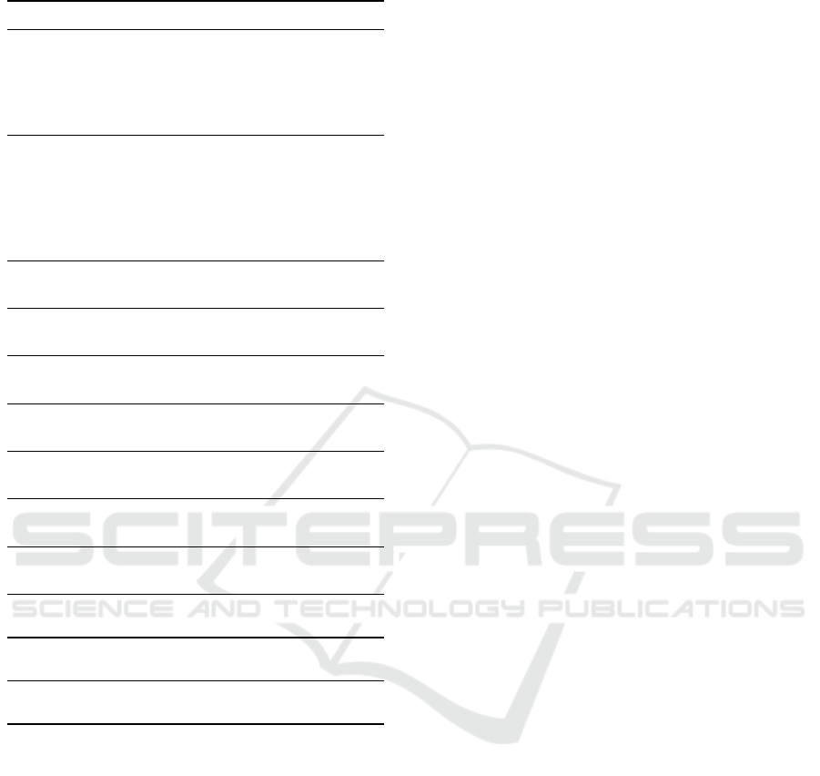
Table 4: Solutions recommended by our plugin.
Solution Recommended Safety Patterns
0 Simplex Architecture for tolerating the soft-
ware fault FT1, i.e., the pattern is applied to
ACC. Heterogeneous Duplex for tolerating
the hardware fault FT2, i.e., the pattern is
applied to EB.
1 Two instances of the Heterogeneous Du-
plex pattern, where the first instance toler-
ates the software fault FT1 (i.e., pattern is
applied to ACC), and the second instance
tolerates the hardware fault FT2 (i.e., pat-
tern is applied to EB).
2 Acceptance Voting for fault FT1. Hetero-
geneous Duplex for fault FT2.
3 Simplex Architecture for fault FT1. Triple
Modular Redundancy for fault FT2.
4 Heterogeneous Duplex for fault FT1.
Triple Modular Redundancy for fault FT2.
5 Acceptance Voting for fault FT1. Triple
Modular Redundancy for fault FT2.
6 Simplex Architecture for fault FT1. Homo-
geneous Duplex for fault FT2.
7 Heterogeneous Duplex for fault FT1. Ho-
mogeneous Duplex for fault FT2.
8 Acceptance Voting for fault FT1. Homoge-
neous Duplex for fault FT2.
9 Simplex Architecture for fault FT1. Moni-
tor Actuator for fault FT2.
10 Heterogeneous Duplex for fault FT1. Mon-
itor Actuator for fault FT2.
11 Acceptance Voting for fault FT1. Monitor
Actuator for fault FT2.
specified as a first-order logic language that can be
automated by solving techniques such as Satisfiabil-
ity Modulo Theories (SMT) (de Moura and Bjørner,
2008). The combination of the proposed DSL with
the designed system architectures enabled the appli-
cability of the semi-automated design space explo-
ration for allocating software components into hard-
ware units. This approach has been extended to en-
able a synthesis of the topology of technical platforms
together with a deployment (Eder et al., 2018b). The
approach has been implemented as a feature of AF3.
Safety Pattern Synthesis currently deals with require-
ments (in terms of allocation constraints) provided by
SAFPAT in a manual fashion. We believe that we
can combine our work with (Eder et al., 2018b)(Eder
et al., 2017) to implement these requirements in an
automated fashion.
6 CONCLUSION
This paper presented Safety Pattern Synthesis – a plu-
gin for automating the recommendation of safety pat-
terns within the model-based system engineering tool
AutoFOCUS3. Safety Pattern Synthesis is guided
by the results of a safety analysis. It takes as in-
put information on how faults may trigger identified
hazards in the system architecture. Guided by this
information, Safety Pattern Synthesis automatically
recommends safety patterns to address the identified
hazards. Safety Pattern Synthesis also recommends
requirements (w.r.t. the recommended patterns and
safety integrity) that shall be implemented during the
system development.
Safety Pattern Synthesis has been developed with
the intention of reducing the effort required by safety
engineers while carrying out a safety analysis on
safety-critical systems such as autonomous vehicles.
ACKNOWLEDGEMENTS
We thank Christoph Ainhauser and Sandro N
¨
uesch
for their help in the early phase of this work.
REFERENCES
Amorim, T., Martin, H., Ma, Z., Schmittner, C., Schnei-
der, D., Macher, G., Winkler, B., Krammer, M., and
Kreiner, C. (2017). Systematic Pattern Approach for
Safety and Security Co-engineering in the Automotive
Domain. In Tonetta, S., Schoitsch, E., and Bitsch, F.,
editors, SAFECOMP 2017.
Aravantinos, V., Voss, S., Teufl, S., H
¨
olzl, F., and Sch
¨
atz, B.
(2015). AutoFOCUS 3: Tooling concepts for seam-
less, model-based development of embedded systems.
In ACES-MB, pages 19–26.
Armoush, A. (2010). Design Patterns for Safety-Critical
Embedded Systems. PhD thesis, RWTH Aachen Uni-
versity.
Avizienis, A., Laprie, J.-C., Randell, B., and Landwehr,
C. E. (2004). Basic concepts and taxonomy of depend-
able and secure computing. IEEE Trans. Dependable
Secur. Comput., 1(1):11–33.
Bak, S., Chivukula, D. K., Adekunle, O., Sun, M., Cac-
camo, M., and Sha, L. (2009). The system-level sim-
plex architecture for improved real-time embedded
system safety. In 15
th
IEEE Real-Time and Embed-
ded Technology and Applications Symposium, RTAS,
pages 99–107. IEEE Computer Society.
Barner, S., Chauvel, F., Diewald, A., Eizaguirre, F., Hau-
gen, Ø., Migge, J., and Vasilevskiy, A. (2018). Mod-
eling and Development Process, pages 87–161. CRC
Press.
MODELSWARD 2022 - 10th International Conference on Model-Driven Engineering and Software Development
46

Barner, S., Diewald, A., Migge, J., Syed, A., Fohler, G.,
Faug
`
ere, M., and Gracia P
´
erez, D. (2017). DREAMS
Toolchain: Model-Driven Engineering of Mixed-
Criticality Systems. In Proceedings of the ACM/IEEE
20
th
International Conference on Model Driven En-
gineering Languages and Systems (MODELS ’17),
pages 259–269. IEEE.
Belmonte, F. and Soubiran, E. (2012). A model based ap-
proach for safety analysis. In Ortmeier, F. and Daniel,
P., editors, Computer Safety, Reliability, and Secu-
rity - SAFECOMP 2012 Workshops: Sassur, ASCoMS,
DESEC4LCCI, ERCIM/EWICS, IWDE, Magdeburg,
Germany, September 25-28, 2012. Proceedings, vol-
ume 7613 of Lecture Notes in Computer Science,
pages 50–63. Springer.
Biondi, A., Nesti, F., Cicero, G., Casini, D., and Buttazzo,
G. C. (2020). A safe, secure, and predictable soft-
ware architecture for deep learning in safety-critical
systems. IEEE Embed. Syst. Lett., 12(3):78–82.
Dantas, Y. G., Kondeva, A., and Nigam, V. (2020). Less
manual work for safety engineers: Towards an auto-
mated safety reasoning with safety patterns. In ICLP.
de Moura, L. M. and Bjørner, N. (2008). Z3: An Efficient
SMT Solver. In Ramakrishnan, C. R. and Rehof, J.,
editors, TACAS 2008, volume 4963 of Lecture Notes
in Computer Science, pages 337–340. Springer.
Douglass, B. P. (2012). Real-Time Design Patterns: Robust
Scalable Architecture for Real-Time Systems.
Eder, J., Bahya, A., Voss, S., Ipatiov, A., and Khalil, M.
(2018a). From deployment to platform exploration:
Automatic synthesis of distributed automotive hard-
ware architectures. In MODELS 2018, MODELS ’18,
page 438–446.
Eder, J., Bayha, A., Voss, S., Ipatiov, A., and Khalil,
M. (2018b). From deployment to platform explo-
ration: Automatic synthesis of distributed automo-
tive hardware architectures. In Wasowski, A., Paige,
R. F., and Haugen, Ø., editors, Proceedings of the
21th ACM/IEEE International Conference on Model
Driven Engineering Languages and Systems, MOD-
ELS 2018, pages 438–446. ACM.
Eder, J., Voss, S., Bayha, A., Ipatiov, A., and Khalil, M.
(2020). Hardware architecture exploration: automatic
exploration of distributed automotive hardware archi-
tectures. Software and Systems Modeling.
Eder, J., Zverlov, S., Voss, S., Khalil, M., and Ipatiov, A.
(2017). Bringing DSE to Life: Exploring the Design
Space of an Industrial Automotive Use Case. In MOD-
ELS 2017, pages 270–280. IEEE Computer Society.
EmbASP (2018). EmbASP. Available at https://www.
mat.unical.it/calimeri/projects/embasp/.
fortiss GmbH (2020). AutoFOCUS 2.19. Available at
https://www.fortiss.org/en/publications/software/
autofocus-3.
IEC61508 (2010). IEC 61508, Functional safety of
electrical/electronic/programmable electronic safe-
tyrelated systems – Part 7: Overview of tech-
niques and measures. Available at http://www.
cechina.cn/eletter/standard/safety/iec61508-7.pdf.
ISO26262 (2018). ISO 26262, road vehicles —
functional safety — part 6: Product de-
velopment: software level. Available at
https://www.iso.org/standard/43464.html.
Leone, N., Pfeifer, G., Faber, W., Eiter, T., Gottlob, G.,
Perri, S., and Scarcello, F. (2006). The DLV system
for knowledge representation and reasoning. ACM
Trans. Comput. Log., 7(3):499–562.
Martin, H., Ma, Z., Schmittner, C., Winkler, B., Kram-
mer, M., Schneider, D., Amorim, T., Macher, G., and
Kreiner, C. (2020). Combined automotive safety and
security pattern engineering approach. Reliab. Eng.
Syst. Saf., 198:106773.
Papadopoulos, Y., Walker, M., Parker, D., Ruede, E.,
Hamann, R., Uhlig, A., Graetz, U., and Lien, R.
(2011). Engineering failure analysis and design op-
timisation with HiP-HOPS. Journal of Engineering
Failure Analysis, 18(2):590–608.
Preschern, C., Kajtazovic, N., and Kreiner, C. (2013a).
Building a safety architecture pattern system. In van
Heesch, U. and Kohls, C., editors, Proceedings of the
18th European Conference on Pattern Languages of
Program, EuroPLoP 2013, pages 17:1–17:55. ACM.
Preschern, C., Kajtazovic, N., and Kreiner, C. (2013b). Se-
curity analysis of safety patterns. PLoP, pages 12:1–
12:38.
SAEJ3061 (2012). SAE J3061: Cybersecurity guidebook
for cyber-physical vehicle systems. Available from
https://www.sae.org/standards/content/j3061/.
Safety Pattern Synthesis (2021). Safety Pattern Synthe-
sis. Available at https://download.fortiss.org/ pub-
lic/MODELSWARD2022/SafetyPatternSynthesis.zip.
Sljivo, I., Uriagereka, G. J., Puri, S., and Gallina, B. (2020).
Guiding assurance of architectural design patterns for
critical applications. J. Syst. Archit., 110:101765.
A Model-based System Engineering Plugin for Safety Architecture Pattern Synthesis
47
