
Conversion Method of MATLAB/Simulink Model for a Functional
Resonance Analysis Method-based Model
Masamichi Kakeshita
1 a
, Kenji Hisazumi
2 b
, Yasutaka Michiura
3
, Keita Sakemi
3
and Michihiro Matsumoto
3
1
Kyushu University, 744 Motooka, Nishi-ku, Fukuoka, 819-0395, Japan
2
Department of Electronic Information Systems, Faculty of Systems Science and Engineering,
Shibaura Institute of Technology, 307 Fukasaku, Minuma-ku, Saitama-shi, Saitama, 337-8570, Japan
3
Japan Manned Space Systems Corporation, 8F, Otemachi Bldg., 1-6-1, Otemachi, Chiyoda-ku, Tokyo, 100-0004, Japan
Keywords:
Embedded System, Safety Analysis, MATLAB/Simulink, Functional Resonance Analysis Method.
Abstract:
In recent years, model-based development (MBD) has become popular in control-embedded systems, and
development specifications are being written using MATLAB/Simulink and other tools. The functional res-
onance analysis method (FRAM) is used for safety analysis of socio-technical systems. It is used to foster
success factors without being trapped in failures. Application of FRAM to MBD models is expected to
improve the quality of MBD models from a new perspective; however, an approach for the application of
FRAM to MBD has not been established yet. Therefore, in this study, we proposed a method to convert
MATLAB/Simulink models into FRAM models. Consequently, the application of the proposed method to the
Simulink model led to an improvement through creation and analysis of the FRAM model. In contrast, there
are certain scenarios that can occur in the Simulink model that are not represented in the completed FRAM
model, as the FRAM model only represents the interactions inside the system, which makes it difficult to thor-
oughly analyze the system with respect to external influences. Our future work shall include a further study
on how to represent information when converting MATLAB/Simulink models to FRAM models and further
applying the method to Simulink models that users can directly modify.
1 INTRODUCTION
Previously, we wrote development specifications for
embedded systems in control systems using natu-
ral language during requirements analysis, followed
by the design process. In recent years, however,
model-based development (MBD) has gained pop-
ularity, and we now write development specifica-
tions in MBD models, such as MATLAB/Simulink
or Simulink models instead. Conventional develop-
ment specifications, which were earlier written in nat-
ural language, posed the risk of varied interpretations
by various people, owing to their ambiguous descrip-
tions. However, Simulink models can eliminate such
risks because they are expressed in an elaborate man-
ner.
The functional resonance analysis method
(FRAM)(Hollnagel, 2017) is a safety analysis
method for sociotechnical systems. Traditional safety
analysis methods, such as fault tree analysis (Vesely
a
https://orcid.org/0000-0002-0308-0566
b
https://orcid.org/0000-0003-2452-6552
et al., 1981), are based on the idea that poor outcomes
result from failures; however, success often accounts
for the majority of events. Furthermore, there are
various cases in which successful events exist despite
the occurrence of unexpected accidents. Therefore,
it is not necessarily reasonable to focus only on
failures. FRAM, on the other hand, defines functions
and characterizes each function based on six different
aspects to create a model and conduct an analysis of
the variation of these functions. Thus, it allows us
to analyze without getting trapped in failures, and
cultivate success factors, such as ”how does it work
well?”.
As mentioned earlier, new safety analysis meth-
ods are emerging, and the application of these meth-
ods to Simulink models may lead to new discoveries.
However, thus far, no method for applying FRAM to
Simulink models has been established. In fact, var-
ious difficulties have been encountered in the appli-
cation of FRAM to Simulink models. The develop-
ment specifications of MBD are often at a low level
of abstraction. However, creating a FRAM model re-
quires reverse modeling with a detailed understand-
234
Kakeshita, M., Hisazumi, K., Michiura, Y., Sakemi, K. and Matsumoto, M.
Conversion Method of MATLAB/Simulink Model for a Functional Resonance Analysis Method-based Model.
DOI: 10.5220/0010845600003119
In Proceedings of the 10th International Conference on Model-Driven Engineering and Software Development (MODELSWARD 2022), pages 234-241
ISBN: 978-989-758-550-0; ISSN: 2184-4348
Copyright
c
2022 by SCITEPRESS – Science and Technology Publications, Lda. All rights reserved
!"#$%&"'(&"%)*$%+&'+,-'.&$/+)"'.0,)*0&'123)"/3
!"#$"%&'(%%) *))$+$,"*-&-,*)$"#
.-$/*+%.,"+0,-12'+%/
3*"&4,*) !"#$"%&1(%%)
!-%5+0$5*-12'+%/
4
5+,'&0+-
!
"##$%$&'"()(&"#$'*
+,&+&,%$&')-"').+//#
0
1./,)2/%+&$'%)$')3/(.$4.
5&,64/)3&7+
58/,7&7/%/,)9$.+(":
2/%;5/7+
<'%5/7+
)=3=>%
)?/"%/,=>%
@/64$,/#5/7+
A(&B/,C4%
5/7+/,"%4,/)3&'%,&()38",%
2:.%/7)5,$**/,
3/(.$4.)%&)D/(E$'
D/(E$')%&)3/(.$4.
@/6)5&4%
@/>:>($'*)=$,!
@/>:>($'*)=$,
@/>:>(/)=$,)C'
F"..)-(&B),"%/
<'%/,$&,)9:'"7$>.
@/6)5/7+)>8"'*/
A(&B/,)2+//#)+,&+&,%$&'
GH%/,'"()5/7+
<'%/,'"()%/7+
I("+)='*(/
GH$%)5/7+)J8/"%/,K
5&4%
?/"%/,)3&'%,&(
?/"%)2&4,>/.
?/"%)-,&7)&>>4+"'%.
L5&4%M=3N
L5&4%M?N
L5&4%M=3N
L5&4%M?N
I("+);&.
I"')2+//#),"%/
!O
GH%/,'"()5/7+/,"%4,/)$')3/(.$4.
9$.%,$P4%$&'!
9$.%,$P4%$&')@/64/.%
9$.%,$P4%$&')
G'*$'/)2+//#
3&7+)5&,64/
A(&B/,)2+//#)+,&+
<'%/,'"()%/7+
GH$%)5/7+)J=3K
=3)3&'%,&(
!
G'*$'/).+//#
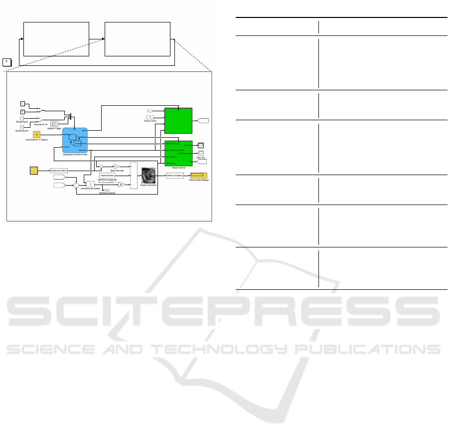
Figure 1: Example of a hierarchical Simulink Model(The
MathWorks Inc., b).
ing of the specifications’ intent. Therefore, it is diffi-
cult to implement FRAM adequately. We herein pro-
posed a method for converting a Simulink model into
a FRAM model.
The rest of this paper is organized as follows: Sec-
tion 2 provides an overview of MATLAB/Simulink;
Section 3 provides an overview of FRAM; Sec-
tion 4 introduces related research; Section 5 pro-
poses a method for converting a Simulink model into
a FRAM model; Section 6 presents a case study of
the proposed method. Finally, in Section 7, we sum-
marize our study and provide future perspectives.
2 MATLAB/SIMULINK
In MATLAB/Simulink, the control logic is described
using a block diagram model (hereinafter referred to
as the Simulink model). Simulating and verifying the
created model enables the detection of control logic
errors at an early stage and reduces the number of
costly prototypes. In addition, representing the con-
trol logic in a model eliminates the risk of different
interpretations by people, which are a result of am-
biguous descriptions. Furthermore, Stateflow illus-
trates how MATLAB and Simulink models react to
input signals, events, and time-related conditions.
In Simulink, the model is hierarchized using sub-
system blocks, which are constructed to output mean-
ingful data in the control logic. The processes for cal-
culating the data are described in the lower levels of
Table 1: Six Aspects.
Aspect Description
Input (I)
What the function
processes or transforms,
or what triggers
the function
Output (O)
The result of
the function working
Precondition (P)
Precondition that
must be present
before the function
can operate
Control (C)
Control the operation
of the function
Resource (R)
Condition necessary
for the function
to continue working
Time (T)
Time constraints that
affect the operation
of the function
the subsystem blocks. Thus, the Simulink model can
be transformed into a structure that can be reused in
subsystem units. Figure 1 shows the climate control
system as an upper-level subsystem, while the control
for adjusting the temperature inside the car is drawn
below it. Thus, this is how functionally related blocks
can be consolidated into one to make the Simulink
model easier to read.
3 FUNCTIONAL RESONANCE
ANALYSIS METHOD (FRAM)
FRAM is a method for safety analysis in socio-
technical systems. It focuses on the interaction of
multiple functions and identifies the strengths and
weaknesses of safety-related systems based on the re-
lationships among the functions.
The FRAM model was created by defining the
functions and aspects that characterize the functions.
The Table 1 shows the six aspects that character-
ize the function. There exists a principle that states
that five of these aspects, which are I, P, C, R, and T,
should correspond to one that is, O, which represents
the output of another function. This assists in deter-
mining the functions that are required to complete the
FRAM model, as the aspects are simply the ”termi-
nals” of one of the functions.
Conversion Method of MATLAB/Simulink Model for a Functional Resonance Analysis Method-based Model
235
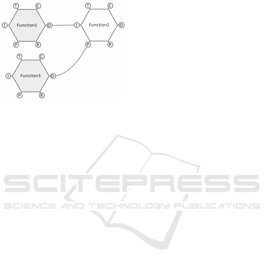
Figure 2: FRAM Model.
To visually represent the connections between
functions, the functions are represented by hexagons.
Each vertex of the hexagon corresponds to one of
the six aspects of the function. By connecting these
hexagons, as shown in Figure 2, we can express
the relationship between the functions. It is vi-
able to identify variations in performance and un-
derstand their unexpected consequences by clarifying
how functions can be combined in such a manner.
4 RELATED WORK
In this section, we introduce related studies on
FRAM. Further, we explain the novelty of this study.
Hirose et al. extended the FRAM, which pro-
vides only a conceptual methodology, to support the
qualitative interpretation of the safety of a target sys-
tem, while quantifying the degree of risk of abnor-
mal functioning(Hirose and Sawaragi, 2020). For this
extension, we introduced the concept of cellular au-
tomaton. It is an automation that induces state tran-
sitions based on the states of neighboring cells. By
considering these cells as functions, we obtained dy-
namically changing patterns. Additionally, the fuzzy
cognitive reality and error analysis method (CREAM)
was used to evaluate the risk. CREAM is a method
used to study how a system progresses based on com-
mon performance conditions (CPCs), while the fuzzy
CREAM is a concept that allows quantitative contin-
uation of the system. A case study was conducted
to apply the FRAM framework in a steel produc-
tion system. The results quantitatively suggested that
even when the same actions are taken for the same
scenario, the risks may differ significantly depending
upon the timing of execution. This research is ex-
pected to expand the FRAM, which originally only
provided concepts that were visually and quantita-
tively tractable.
Studic et al. developed the total April safety man-
agement (TASM) framework for systematic ground
handling safety management on airport aprons(Studic
et al., 2017). The data underlying the development
of this framework were collected as follows: As the
uniqueness of airport safety management is recog-
nized throughout the aviation industry, a literature
review was conducted on five airports that were se-
lected based on expert judgment, such that perfor-
mance variability could be captured in general. Ob-
servations and interviews were conducted over a pe-
riod of 20 days during peak air traffic, for each air-
port. The data obtained from these studies were ana-
lyzed to develop a template for factors that influence
the variability of apron operations. Using this, all
functions and their aspects were theoretically defined.
Therefore, the accuracy and reliability of the analysis
would be improved. This research is expected to en-
able conducting a more practically effective analysis
using FRAM.
In this study, we have proposed a new approach to
build FRAM models in the area of embedded control
systems.
5 METHODOLOGY FOR
CREATING A FRAM MODEL
USING THE SUBSYSTEM
TABLE AND SIGNAL LINE
TABLE
In this section, we propose a method for converting a
Simulink model to a FRAM model. First, we create a
subsystem table to clarify the role of each subsystem.
Next, a signal line table is created for easier under-
standing of the role of each signal line. In addition,
the level of abstraction of the functions in the FRAM
model is determined. By setting the appropriate level
of abstraction, we create a FRAM model that focuses
on the details, while simultaneously providing a com-
plete overview. The FRAM model is then created by
defining the aspects for each function. We have ex-
plained these steps in detail in the following sections.
5.1 Step 1: Identification of Functions
In Step 1, we identify the functions in the FRAM
model, assuming that the Simulink model is hierar-
chically organized by subsystem blocks.
MODELSWARD 2022 - 10th International Conference on Model-Driven Engineering and Software Development
236
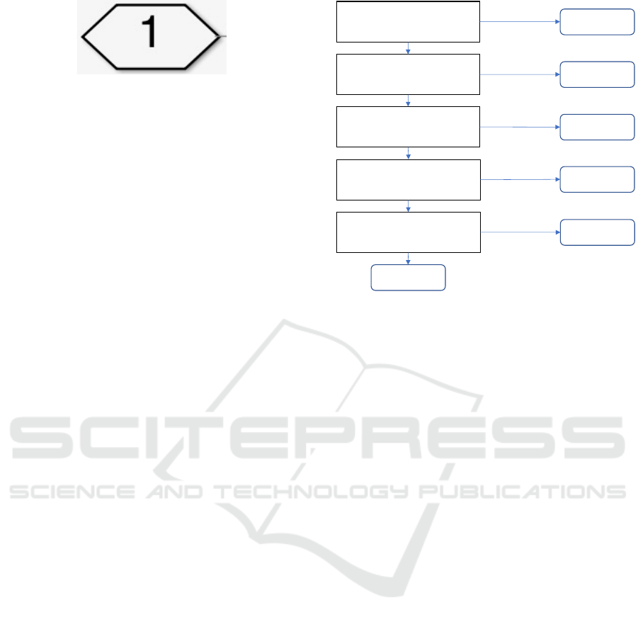
Figure 3: Signal lines that are not treated as input/output.
5.1.1 Creating a Subsystem Table
First, we create a subsystem table from the Simulink
model to clarify the role of each subsystem and the
state flow chart. The subsystem table follows the for-
mat depicted in Table 2. Each entry in the subsystem
table should contain the name of the subsystem, an
overview of the roles played by the subsystem, the
inputs and outputs of the subsystem, and the subsys-
tems that comprise the subsystem. At this point, the
signals handled by the terminals shown in Figure 3
are not treated as inputs or outputs of the subsystem.
This is because this port acts as a terminal to transfer
across the boundary of the subsystem, known as the
connection port, and does not affect the subsystem.
This clarifies the purpose of each subsystem.
5.1.2 Creating a Signal Line Table
Following the construction of the subsystem table, the
signal line table is created. The signal table is cre-
ated based on the format shown in Table 3. Each
line should contain information about the signals that
appear in the subsystem table. Specifically, it de-
scribes which subsystem the signal belongs to, its sig-
nal name, role, unit, and whether there is an equiva-
lent signal line, and if so, what it is. An equivalent
signal line refers to a signal that branches from the
same signal line. Thus, the aspect of each signal line
to the subsystem can be clarified.
5.1.3 Function Abstraction
Once the subsystem and signal line tables are cre-
ated, we are required to determine the level of ab-
straction of the functions that are to be converted into
the FRAM model. When the level of abstraction is
high, it is easier to observe the entire picture of the
target model; however, it is difficult to grasp the de-
tails. In contrast, when the level of abstraction is low,
it is easier to understand the specific details; however,
the scale of the FRAM model may become too large.
Thus, there is a trade-off between the level of abstrac-
tion of the functions in the FRAM model, and the
ease of grasping the overall image of the target model.
Therefore, it is siginificant to determine an appropri-
ate level of abstraction.
!"#$"#
%"&'()*+,-.+,"'/-0(-1+#+-#2+#-
+('-#2'-/0"(*'-03-#2'-0"#$"#
4#-50",1-*+"/'-#2'-'%#)('-
/"6/7/#'&-#0-/#0$-
3"%*#)0%)%8-+%1-*0%#)%"0"/
4#-50",1-*+"/'-#2'-'%#)('-
/"6/7/#'&-#0-/#0$-
3"%*#)0%)%8-+%1-1)/*('#'
#)&'9(',+#'1-/)8%+,
!"#$"#-
:!;
4%$"#-
:4;
<)&'-
:<;
='/0"(*'-
:=;
>('*0%1)#)0%-
:>;
!"#
!"#
!"#
!"#
!"#
$%
$%
$%
$%
$%
?0%#(0,-
:?;
Figure 4: The mapping between inputs and outputs, and
aspects.
Currently, there are no definitive ways to deter-
mine this. As a general rule of thumb, we first de-
termine the level of abstraction for each actor in the
Simulink model. This is because we intend to ob-
serve how each actor is affected by other actors in the
FRAM model and how it affects other actors. Within
an actor, it is better to have a higher hierarchy than
a hierarchy consisting only of subsystems without re-
turn values. This is because many such subsystems
only perform procedurally necessary operations and
are unlikely to provide valid information when con-
verted to FRAM models. In addition, the hierarchy
should be such that internal interactions are not sig-
nificantly lost. This is done to avoid the loss of in-
formation about how each subsystem affects the ac-
tors within each other. Convert the subsystem blocks
and state flow charts in the determined hierarchy into
FRAM based model functions on a one-to-one basis.
5.2 Step 2: Classification of Inputs and
Outputs
Once the abstraction level of a function is determined,
we define the aspects of that function. Aspects should
be mapped one-to-one to the inputs and outputs of the
subsystem in the Simulink model. The mapping be-
tween inputs and outputs, and aspects is shown in Fig-
ure 4. First, we classify the output into O. Next, we
classify the signals that are direct numerical values or
data that are the source of the output as I. We convert
time-related signals to T. Furthermore, we define sig-
nals whose input would cause the entire subsystem to
Conversion Method of MATLAB/Simulink Model for a Functional Resonance Analysis Method-based Model
237
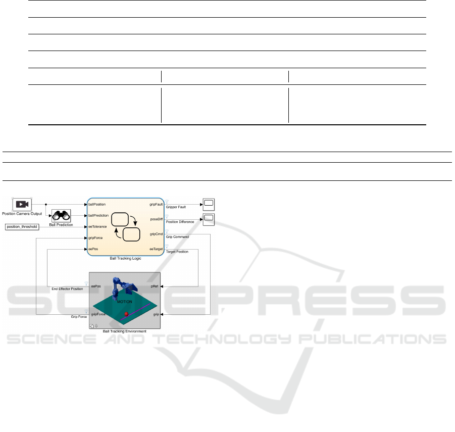
Table 2: Subsystem Table.
Subsystem name
Name of the subsystem
Overview
Overview of the role of the subsystem
Input Comprised Subsystem Output
Describe the names of
all inputs in the Subsystem
Describe the names of
all comprised subsystems
in the Subsystem
Describe the names of
all outputs in the Subsystem
Table 3: Signal line Table.
Subsystem Signal line name Overview Unit Link
The subsystem to which
the signal line belongs
Describe the names of all signal lines
in the Simulink model
Overview of the role of the signal line Unit of the value
Describe the names of all signals that
branches from the same signal line
Figure 5: Simulink model for the case study (The Math-
Works Inc., a).
stop functioning, as P if the signal is discrete, and R,
otherwise. If none of the aforementioned criteria are
satisfied, the signal is assigned to C.
6 CASE STUDY
6.1 MATLAB/Simulink Model for the
Case Study
In this section, we focus on a project called openMa-
nipulatorBallTracking(The MathWorks Inc., a). This
model simulates a manipulator tracking a ball and
grabbing it with its grip. The top floor of the Simulink
model for this project is shown in Figure 5. It con-
sists of the following four subsystems: Ball Track-
ing Logic controls the manipulator, and Ball Tracking
Environment manages the state of the objects repre-
sented in the simulator, such as the ball, manipulator,
and ground. Furthermore, Position Camera Output is
a camera used for tracking the ball. Ball Prediction
estimates the position of the ball using this informa-
tion.
6.2 Implementation
The proposed transformation method is applied to the
Simulink model in Section 6.1, and the completed
FRAM model diagram and its safety analysis using
the diagram are also described.
6.2.1 FRAM Model
The proposed method was applied to the OpenManip-
ulatorBallTracking.
For the sake of space, the subsystem table and sig-
nal line table created along the way correspond to the
Robot, which is one of the subsystems in the Simulink
model. The Simulink model of Robot is shown in Fig-
ure 6, where Robot is the subsystem that determines
the angle of each joint of the manipulator.
The subsystem table is presented in Table 4. As
for input/output, the commands were the input and
sensorData was the output for the reasons described in
Section 5.1.1, whereas W and Bfa were not treated as
either input or output. For Comprised Subsystem, all
the Subsystems included in the Robot were described.
The signal line table is presented in Table 5. All
the signal lines that appear in the Simulink model are
listed according to the proposed method. The outline
of the signal lines was also obtained by reading the
documentation of the Simulink model and verifying
the Simulink references.
We constructed the FRAM model using the sub-
system and signal lines table created in the man-
ner mentioned above. The full model is shown in
Figure 7. The actors were ”Camera,” ”Ball Pre-
MODELSWARD 2022 - 10th International Conference on Model-Driven Engineering and Software Development
238
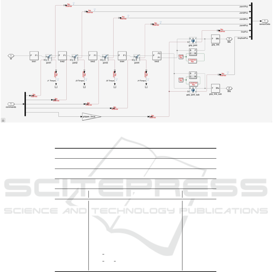
Figure 6: Robot, one of the Subsystems in the OpenManipulatorBallTracking.
Table 4: Part of the Subsystem table created by applying the proposed method to openManipulatorBallTracking.
Subsystem name
Robot
Overview
Determine the angle of each joint of the manipulator
Input Comprised Subsystem Output
commands Translational Simscape Multibody sensorData
Translational Simscape Multibody1
link1
link2
link3
link4
link5
grip link
grip link sub
world
diction,” ”BallTrackingLogic,” ”Robot,” ”Ball and
Floor,” and ”World,” and the level of abstrac-
tion was determined based on the criteria de-
scribed in Section 5.1.3. In the case of Ball-
TrackingLogic, there exists a relationship between
the subsystems ”RobotMotion.GripSet,” ”RobotMo-
tion.Manipulator,” ”Gripper,” and ”Gripper.SetGrip,”.
Because most of the deeper subsystems do not have a
return value, the level of abstraction was determined
on this scale. The signal line W that extends from the
world to the robot, provides a virtual space in the sim-
ulator. Because this is a continuous signal line that is
a prerequisite for the robot to function, we classified
it as R from the viewpoint of the robot.
6.2.2 Analysis
We performed a safety analysis on the FRAM model
created in Section 6.2.1. Specifically, we examined
scenarios that can be assumed when each function
fails. It was determined that there are various sce-
narios in which the failure of a certain function could
cause the entire system to stop operating. However,
we also determined that there is a success factor,
where the system converges to some state without
failure, because the scenarios other than the release of
the grabbed ball are not undefined behaviors. From
these results, we conclude that unexpected stoppages
can be avoided by setting a timeout, among other op-
Conversion Method of MATLAB/Simulink Model for a Functional Resonance Analysis Method-based Model
239

Table 5: Part of the Signal line table created by applying the proposed method to openManipulatorBallTracking.
Subsystem Signal line name Overview Unit Link
Robot W Virtual Space /world/F1
Bfa Grip Positon
Bfb Grip Position
commands State specifications for joints and grips /Inverse Kinematics/jointState,/Motion Actuated/grip
sensorData Location information for each part
Joint1Pos Position of joint 1
Joint2Pos Position of joint 2
Joint3Pos Position of joint 3
Joint4Pos Position of joint 4
GripPos Grip Position
GripSubPos Position of the other grip
link1 F Virtual Space /Robot/W
F1 Virtual space as seen from Joint 1
link2 F Virtual Space
F1 Virtual space as seen from Joint 2
link3 F Virtual Space
F1 Virtual Space as seen from joint 3
link4 F Virtual Space
F1 Virtual Space as seen from joint 4
link5 F Virtual Space
F1 Virtual Space as seen from gripper 1
F2 Virtual Space as seen from gripper 2
Translational Simscape Multibody B Virtual Space of gripper 1 in the original frame
F Virtual Space of gripper 1 in the next frame
R Gripper Speed
C Gripper Acceleration
Translational Simscape Multibody1 B Virtual Space of gripper 2 in the original frame
F Virtual Space of gripper 2 in the next frame
R Gripper Speed
C Gripper Acceleration
grip link F Virtual Space of gripper 1 in the next frame /Translational Simscape Multibody1/F
Bfb Position of gripper 1 /Robot/Bfb
grip link sub F Virtual Space of gripper 2 in the next frame
Bfa Position of gripper 2 /Robot/Bfa
tions. Thus, we were able to identify success factors
and risk factors from the FRAM model we created
and propose improvement measures.
In contrast, let us consider a scenario in which
the ball tracking logic fails, and it judges that the
ball is being grabbed even though it is not. In this
case, according to the Simulink model, the manipu-
lator returns to the home position and terminates the
program because of the judgment that it has grabbed
the ball, but we cannot read this information from the
FRAM model alone. Hence, it was determined that
the FRAM model may not be able to represent the
necessary information for analysis. In addition, be-
cause the FRAM model represents only the internal
interactions of the system, it is difficult to analyze ex-
ternal influences, such as user input and weather con-
ditions.
6.3 Result
By using the method proposed in Section 5 in the
Simulink model, we were able to create a FRAM
model. Based on its analysis, we proposed improve-
ment measures. However, it was determined that it
is difficult to completely grasp the information of the
Simulink model using only the FRAM model. In ad-
dition, although we were able to assume the scenarios
caused by internal changes in the system, it became
clear that it is currently a challenge to conduct an anal-
ysis that takes the external effects into account.
7 CONCLUSION
We converted the MATLAB/Simulink model into a
FRAM model by creating a subsystem and a signal
line table from the MATLAB/Simulink model, and
identifying the functions and their aspects from the
information in the tables. By applying this method to
an actual Simulink model, we further created a FRAM
model. In addition, by analyzing the FRAM model,
we discovered problems in the system and suggested
improvements. However, it was determined that the
FRAM model alone could not cover all the informa-
tion in the Simulink model. The analysis of the model
considering external influences, such as human input
and weather was also determined to be a challenge.
In the future, it is necessary to consider how to ex-
MODELSWARD 2022 - 10th International Conference on Model-Driven Engineering and Software Development
240
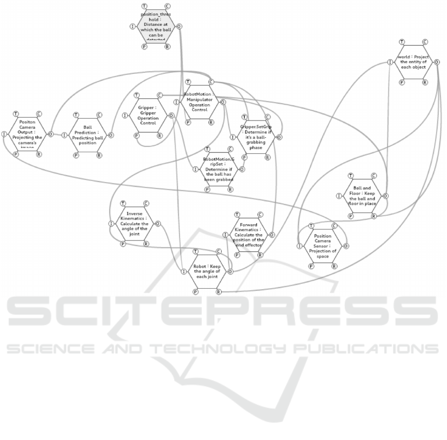
Figure 7: FRAM model created by applying the proposed method to openManipulatorBallTracking.
press the information in the Simulink model without
omissions, and how to express the external interac-
tion. Further, it is also required to construct a trans-
formation method that considers these factors, and to
further apply the transformation method to Simulink
models that are directly manipulated by users.
REFERENCES
Hirose, T. and Sawaragi, T. (2020). Extended fram model
based on cellular automaton to clarify complexity
of socio-technical systems and improve their safety.
Safety Science, 123:104556.
Hollnagel, E. (2017). FRAM: the functional resonance
analysis method: modelling complex socio-technical
systems. CRC Press.
Studic, M., Majumdar, A., Schuster, W., and Ochieng, W. Y.
(2017). A systemic modelling of ground handling ser-
vices using the functional resonance analysis method.
Transportation Research Part C: Emerging Technolo-
gies, 74:245–260.
The MathWorks Inc. simulinkdronereferenceapp.
github.com/mathworks-robotics/designing-robot-
manipulator-algorithms.git.
The MathWorks Inc. Vehicle electrical and climate con-
trol systems. jp.mathworks.com/help/simulink/slref/
vehicle-electrical-and-climate-control-systems.html.
Vesely, W. E., Goldberg, F. F., Roberts, N. H., and Haasl,
D. F. (1981). Fault tree handbook. Technical report,
Nuclear Regulatory Commission Washington DC.
Conversion Method of MATLAB/Simulink Model for a Functional Resonance Analysis Method-based Model
241
