
Model-driven Engineering and Simulation of Industrial Robots with ROS
Niels Hoppe
1 a
and Jan Hoffschulte
2
1
Fraunhofer FOKUS, Kaiserin-Augusta Allee 31, 10589 Berlin, Germany
2
Humboldt University Berlin, Dept. of Computer Science, Rudower Chaussee 25, 12489 Berlin, Germany
Keywords:
Industrial Robotics, Model-driven Engineering, Robot Operating System, Simulation.
Abstract:
Industrial automation is the earliest and best established application of robotics. Today, however, increasing
complexity of industrial robotics applications places high demands on system integrators. In order to make this
complexity more manageable, we developed a model-driven engineering approach for the modular composi-
tion and simulation of complex ensembles of industrial robots based on the Robot Operating System (ROS).
The approach consists of a domain-specific profile for the Unified Modeling Language (UML) and a model-
to-text transformation for automatic generation of artifacts required for control and simulation. The modelling
methodology and code generation were successfully applied to a use case example which is also described in
the paper.
1 INTRODUCTION
Industrial automation is the earliest and best estab-
lished application of robotics. Today’s high degree of
robotic automation in modern manufacturing and lo-
gistics culminates in lights-out manufacturing, with
factories running entirely autonomous and humans
acting merely as bystanders to oversee smooth pro-
duction flow. This is enabled by complex ensembles
of industrial robots, placing high demands on the ven-
dors extending their capabilities, but also in particular
on system integrators who must ensure the correct in-
terplay of diverse robotic components. System inte-
gration and virtual commissioning involve large man-
ual effort by engineers, and expert knowledge is often
required even for routine tasks. This is to a great ex-
tent caused by a lack of formalization, since engineer-
ing data such as, e.g., data sheets and technical spec-
ifications, are often hidden in non-machine-readable
documents. Also, despite software playing an inte-
gral part in any modern automation solution, system
integration in industrial robotics is often still seen as a
mechanical and electrical engineering discipline. As
a result, recent advancements in software engineering
are adopted very slowly.
With the work presented in this paper we intend to
bring model-driven engineering (MDE) to the realm
of robotics system integration and simulation based
a
https://orcid.org/0000-0003-3736-8477
on the Robot Operating System (ROS). MDE is a
well-established practice in software engineering and
has been leveraged in robotics programming before.
However, the main concern of existing approaches is
behavioral modelling aimed at analysing and generat-
ing control software for robots. In contrast, our work
targets structural properties of components and robots
with the aim to easily compose and simulate complex
robot ensembles.
The rest of this paper is structured as follows: Sec-
tion 2 details the motivation and goals of our work,
followed by a brief discussion of related work in
section 3. Section 4 then introduces our modelling
methodology, section 5 explains the code generation
and section 6 presents a use case example for evalua-
tion. Finally, section 7 summarizes and concludes the
paper with an outlook on future work.
2 MOTIVATION AND GOALS
Implementing and simulating robotics applications
with ROS requires a lot of manual coding in a variety
of different languages and textual notations. Infor-
mation is often spread and replicated across multiple
files for different purposes and tools. Also, lacking
means for structured reuse often leads to code dupli-
cation (Estefo et al., 2015). This creates a steep learn-
ing curve for beginners, but also makes it hard even
for experienced developers getting an overview of a
264
Hoppe, N. and Hoffschulte, J.
Model-driven Engineering and Simulation of Industrial Robots with ROS.
DOI: 10.5220/0010883600003119
In Proceedings of the 10th International Conference on Model-Driven Engineering and Software Development (MODELSWARD 2022), pages 264-270
ISBN: 978-989-758-550-0; ISSN: 2184-4348
Copyright
c
2022 by SCITEPRESS – Science and Technology Publications, Lda. All rights reserved

system, slowing down the development and possibly
resulting in inconsistencies and faults that are diffi-
cult to debug. We consider the fast evolution, open-
ness and diversity of tools and standards a strength
of ROS. However, the fragmented nature of the tool
landscape and competing and evolving standards fur-
ther aggravate the issue, as applications become prone
to changes of the targeted tools and underlying tech-
nologies. Missing standards and heterogeneity make
reuse and composition a highly manual process and
less accessible to tool support and automatic valida-
tion.
As a solution, we suggest an MDE approach that
allows graphically designing robots based on reusable
components. Code generation is then applied in order
to reduce manual programming effort. The objective
of our work is speeding up the development and in-
creasing maintainability of ROS applications through
formalization, modularization and automation. For-
malization is a prerequisite for automation and can
also enable advanced reasoning, model-checking and
knowledge management. Modularization is intended
to facilitate reuse and simplify configuration. Au-
tomation helps reducing manually written boilerplate
code and supports an efficient and user-friendly work-
flow based on graphical modeling and code genera-
tion. Secondary concerns of our work are portability
across tools, simulators and platform versions, in par-
ticular ROS 1 and ROS 2, as well as integration with
existing ROS packages.
3 RELATED WORK
Many different MDE approaches for robotics have
been and still are being developed. Approaches dif-
fer in the used metamodels and their targeted plat-
forms, functionalities and modelled aspects. Techni-
cally however, most are based on the Eclipse Model-
ing Framework (EMF) and associated tools. A com-
prehensive and recent overview of relevant MDE ef-
forts targeting ROS is found in (Hammoudeh Garcia
et al., 2019) and (Hammoudeh García et al., 2021).
Their work in the context of the SeRoNet project
1
focuses on reverse engineering models from manu-
ally written ROS code. Common to their approach
as well as the ones of SmartSoft (Schlegel and Worz,
1999) including the SmartMDSD toolchain (Stampfer
et al., 2016), BRICS (Bruyninckx et al., 2013) and the
BRIDE toolchain (Bubeck et al., 2014), and ReApp
(Awad et al., 2016) are component-based architec-
tures, either based on the Unified Modelling Lan-
1
https://www.seronet-projekt.de/
guage (UML) or a similar custom metamodel. Also,
they focus mostly on behavioral modelling in contrast
to structural modelling. Another relevant and ongoing
effort is the work on Papyrus for Robotics
2
serving as
an integration platform for MDE approaches from the
RobMoSys project
3
.
In the context of factory automation and ROS,
ROS Industrial
4
must also be mentioned. This open-
source project is led by an international consortium
and develops capabilities for industrial robotics and
automation with ROS. It has recently been supported
by the ROSIN project, aiming at providing ROS In-
dustrial quality-assured robot software components.
Three related sub-projects stem from the context of
ROSIN
5
:
The Robotics Language (RoL) proposes a frame-
work for domain specific languages to describe robot
behavior. It allows to integrate mini-abstraction lan-
guages in order to describe behavior in terms of,
e.g., a state machine and can thus be seen as an
MDE approach for ROS-based systems. However, it
does not provide capabilities for structural modelling.
In contrast, the Hardware Robot Information Model
(HRIM) (Zamalloa et al., 2018) proposes a common
software interface for robot modules, facilitating in-
teroperability, reconfigurability and flexibility. It fo-
cuses on communication, though, and does not con-
sider physical structure. The ROS-MDD project is an
effort to integrate HRIM into Papyrus for Robotics,
but also to provide code generation and round-trip en-
gineering. Unfortunately, the status of this work is
unknown. Finally, there exist two related standardiza-
tion efforts by the OMG: Robotic Technology Compo-
nent (RTC) (The Object Management Group, 2012)
and Hardware Abstraction Layer for Robotic Tech-
nology (HAL4RT) (The Object Management Group,
2016). The main focus of these standards is to pro-
vide standardized programming interfaces for differ-
ent kinds of robotic hardware components. Like
HRIM, they do not consider physical structure.
We can conclude that many promising MDE
projects targeting ROS and robotics in general ex-
ist, but they are mostly directed at behavioral mod-
elling. With our work we continue previous structure-
oriented efforts by extending them to physical aspects
and complement the existing behavior-oriented ap-
proaches.
2
https://www.eclipse.org/papyrus/components/robotics/
3
https://robmosys.eu/
4
https://rosindustrial.org/
5
https://www.rosin-project.eu/ftp/{ros-mdd, robotics-
language, hrim}
Model-driven Engineering and Simulation of Industrial Robots with ROS
265

4 MODELLING METHODOLOGY
Owing to the highly generic nature of UML, there is
usually more than one way to model any given sys-
tem. It is nevertheless often useful to choose a specific
modelling methodology in order to reduce ambiguity
and ensure interoperability. In the following we first
outline the structure of the profile and then explain the
intended use of the concepts provided therein.
4.1 Structure of the UML Profile
When modelling, we distinguish four main structural
concepts: packages, basic and composite robot com-
ponents, robots, and robot ensembles. Whereas pack-
ages are a means of arbitrarily structuring the model
and resulting code, the other concepts directly relate
to the actual structure of the modelled system. The
internal structure of these high-level concepts is then
described in terms borrowed from various formats
used in ROS, most notably URDF, SRDF and SDF.
The Unified Robot Description Format (URDF) is
an XML-based format for representing robot models.
URDF is the most prevalent format for this purpose in
the ROS ecosystem, although it has some limitations.
For example, closed kinematic loops can not be ex-
pressed since URDF represents robot models in a tree
structure. Further, it is mostly limited to kinematic
properties and does not allow semantic information to
be included. Such is instead commonly expressed us-
ing the likewise XML-based Semantic Robot Descrip-
tion Format (SRDF). SRDF shares its general struc-
ture and some concepts with URDF, but instead of
physical properties it is targeted at describing groups
of links and joints and their functional interaction. As
a third XML-based format, the Simulation Descrip-
tion Format (SDF) is also used for describing robots,
but also other static and dynamic objects, lighting and
terrain for simulation. This format was originally de-
veloped for the Gazebo robot simulator and has many
commonalities with both, URDF and SRDF. The con-
cepts contained in the profile can be divided into the
following groups:
Infrastructure and Types. Software in ROS is or-
ganized in packages which are represented in the pro-
file by the «ROS Package» stereotype. Robot ensem-
bles are specified using the «Ensemble» stereotype.
The profile also provides certain frequently used data
types, e.g., vectors, quaternions and frames.
Links and Joints. A basic robot model constitutes
of links, i.e., rigid bodies with physical properties,
and joints connecting them. Links and joints are as-
sembled, together with other information on their in-
teraction, into components and robots. In order to
specify links and joints, the profile contains a generic
«Link» stereotype and different stereotypes for var-
ious types of joints, e.g., «FixedJoint», «Revolute-
Joint» and others.
Actuators and Transmissions. An actuator is a
component of a mechanical system translating a con-
trol signal and energy into movement. The most
prevalent type of actuators in robotics are electric mo-
tors. In URDF, transmissions describe the effect an
actuator takes on a joint. Both concepts are repre-
sented in the profile by the «Actuator» stereotype,
a specialization of «Link», and the «Transmission»
stereotype.
Robotic Arms and End Effectors. An essential
feature of industrial robotic arms is their end effec-
tor, i.e., the device at their end designed to inter-
act with the environment. Many different kinds of
end effectors exist for different purposes. Examples
include general-purpose and specialized grippers for
handling, tools for various joining technologies like
welding, gluing, bolting, etc., as well as tools for cut-
ting technologies like laser cutting or milling.
4.2 ROS Packages
For each ROS package certain metadata must be spec-
ified, e.g., author information and dependencies to
other packages. For modelling such metadata, we
use a Package Diagram and Packages decorated with
the «ROS Package» stereotype. Dependencies can
be specified in two different ways, conditional on
whether the depended upon package is part of the
model or not. For packages being part of the model,
dependencies are specified with Dependencies deco-
rated with one of the «exec», «run» or «build» stereo-
types. Other external dependencies can be added
to the respective properties of the «ROS Package»
stereotype.
As a best practice for structuring the model and
resulting code, we suggest to create individual pack-
ages for each robot and tool, as well as an additional
package for the specification of robot ensembles. For
a simple setup with a single robot and tool, this would
result in a package structure as depicted in figure 1
based on ROS Industrial naming conventions.
MODELSWARD 2022 - 10th International Conference on Model-Driven Engineering and Software Development
266
PROJECT...............................................Model
«ROS Package» VENDOR_ROBOT_support......Package
«Robot» ROBOT........................Component
«ROS Package» VENDOR_TOOL_support .......Package
«Component» TOOL....................Component
«ROS Package» PROJECT_simulation ........ Package
«Ensemble» ExampleSetup............Component
Figure 1: Package structure for a single robot and tool.
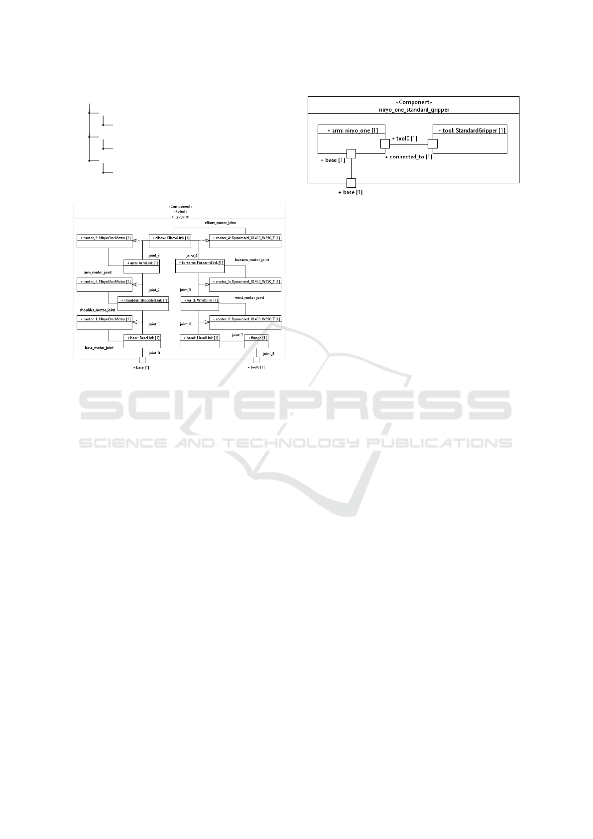
Figure 2: Composite structure diagram of niryo_one robot.
4.3 Components and Composites
Every component, robot and robot ensemble is repre-
sented by a Component in a Class Diagram and dec-
orated with the respective stereotype «Component»,
«Robot» or «Ensemble». The inner structure of a
component or robot is then specified in a Composite
Structure Diagram (CSD). Therein, each link is rep-
resented by a Property. Links can be specified in two
different ways: On the one hand, the «Link» stereo-
type can be added to the Property and the link is spec-
ified in-place. In this case, the type of the Property
is left undefined. On the other hand, the link can be
specified in an accordingly decorated Class acting as
the type of the Property. Whereas the former method
produces more concise models when faced with many
unique links, the latter facilitates the reuse of link
specifications. Joints are represented in the CSD by
Connectors decorated with the appropriate «...Joint»
stereotype and connecting two Properties represent-
ing links. Figure 2 shows the CSD of a robotic arm
and figure 3 shows the composition of the arm with a
tool.
The structure of robot ensembles is specified in a
CSD similar to the inner structure of a complex com-
ponent. Therein, each robot is represented by a Prop-
erty decorated with the «RobotInstance» stereotype
and typed with the respective Component represent-
Figure 3: Composite structure diagram of niryo_one robot
with standard_gripper as tool.
ing the desired robot.
4.4 Actuators and Transmissions
Actuators are modelled as a specialization of links.
The joint an actuator is taking effect on is marked
by a Dependency decorated with the «Transmission»
stereotype and having the respective Connector as its
client and Property as its supplier. Since actuators are
often standardized off-the-shelf components, we rec-
ommend to specify them in an individual Class and
reuse this. However, specifying them in-place, as de-
scribed earlier, is also possible.
4.5 MoveIt Planning Groups
Precisely positioning the end effector at a desired pose
or moving it along a path is the principal function of
a robotic arm. This leads to the problems of forward
kinematics, i.e., calculating the position of the end ef-
fector based on a known state of all joints, and in-
verse kinematics, i.e., calculating a valid joint config-
uration in order to reach a given pose of the end ef-
fector. Whereas the former is relatively easy to solve
with trigonometric formulas, the latter is more com-
plex and may require numerical solutions and heuris-
tics. The MoveIt framework (Coleman et al., 2014) is
a popular choice for ROS developers to solve this.
In order to prepare a component for use with
MoveIt , it can be marked with the «KinematicChain»
stereotype, a concept borrowed from SRDF. A kine-
matic chain is defined through its base link and tip
link, both represented in the profile as properties of
the «KinematicChain» stereotype.
5 CODE GENERATION
As explained earlier, simulating and controlling a
ROS-based robot requires numerous related files in
different formats as input for the tools and processes
involved. A model-to-text transformation allows to
Model-driven Engineering and Simulation of Industrial Robots with ROS
267

VENDOR_ROBOT_support/
CMakeLists.txt...............................meta data
package.xml.................................. meta data
config/
controllers/COMPONENT.yaml
launch/
ROBOT.launch ........................... entry point
urdf/
ROBOT.urdf........................ robot description
ROBOT.xacro....................... robot description
ROBOT_macro.xacro................robot description
COMPONENT_macro.xacro......component description
Figure 4: Files generated for robots and components.
automatically derive these files from the model. This
reduces the manual coding effort and ensures coher-
ence.
In general, the following file types are generated
according to ROS Industrial conventions: component
and robot macros, top-level robot descriptions, launch
files, as well as controller and other configurations.
There is a basic set of files required for simulation and
low-level control of a robot. This is extended by some
additional files required for MoveIt motion planning.
The structure of the generated code is displayed in
figure 4 for generic artifacts and in figure 5 for those
related to motion planning.
Code generation is implemented using Eclipse
Acceleo, a template-based open-source code gener-
ator for EMF models. The targeted ROS version is
ROS noetic, the most current release of ROS 1. In
the following we explain which individual files are
generated from which model elements and for what
purpose.
5.1 Components and Robots
For each component and robot in the model two files
are generated: a component or robot macro and an as-
sociated controller configuration. Macros are a stan-
dard method for reuse and composition in ROS and
their use is encouraged by ROS Industrial conven-
tions. Macros are encoded using the XACRO format.
Controller configurations serve as an input to the
ros_control framework (Chitta et al., 2017). This pro-
vides standardized ROS-based interfaces for different
kinds of robot actuators. It contains several types of
controllers allowing to operate actuators based on ef-
fort, position, velocity or joint trajectory. For any
given robot the desired controllers must be config-
ured based on the transmissions and physical prop-
erties of the actuated joints. For this purpose a suit-
able configuration file for a joint trajectory controller
is generated for every actuated component. We also
add the gazebo_ros_control plugin to the robot, ex-
posing a simulated hardware interface to ros_control
when working in simulation.
For each robot two additional top-level robot de-
scriptions in URDF and SRDF are generated. Their
kinematic structure is identical to that of the respec-
tive robot macro. However, there are tools not sup-
porting the XACRO format and thus depending on
plain URDF. Further, MoveIt requires a robot descrip-
tion in SRDF as well as a set of configuration files for
motion planning. As explained earlier, SRDF is used
to express semantic information, e.g., groups of links
and joints acting as kinematic chains or end effectors,
but also pairs of links which are known never to col-
lide, e.g., because they are adjacent to each other. The
later information is used to enhance the performance
of motion planning by reducing the amount of colli-
sion checks that need to be performed at runtime.
In addition to these macros, robot descriptions and
controller configurations, several other configuration
and launch files required by MoveIt are generated
with predefined usable default values.
5.2 Robot Ensembles
For running simulations of robot ensembles we use
the Gazebo simulator (Koenig and Howard, 2004).
Simulation even of simple setups requires multiple in-
teracting ROS nodes to be launched. roslaunch is a
tool for launching multiple related ROS nodes based
on one or more XML configuration files. One par-
ticular challenge in composing launch files are name
conflicts. These occur often when simulating multiple
instances of similar or identical robots. Name con-
flicts can be avoided by using namespaces for ROS
topics and services, as well as prefixes for names
of links and joints. However, an inconsistent use of
namespaces and prefixes is a common source of er-
rors. The model-to-text transformation automatically
generates consistent launch files for each ensemble in
the model.
In their entirety, the generated files enable simulat-
ing the modelled robots, as well as controlling them
either on a low level based on joint trajectories or by
using the MoveIt move group interface.
6 USE CASE EXAMPLE
In the context of the ITEA3 project eXcellence in
Variant Testing (XIVT) (Schlingloff et al., 2020) we
implemented the XIVT Robotics Demonstrator in or-
der to test and showcase the developed methods. In
its default configuration the demonstrator consists of
MODELSWARD 2022 - 10th International Conference on Model-Driven Engineering and Software Development
268
VENDOR_ROBOT_moveit_config/
CMakeLists.txt...............................meta data
package.xml.................................. meta data
config/
joint_limits.yaml................robot description
kinematics.yaml..................solver parameters
ompl_planning.yaml
ros_controllers.yaml
ROBOT.srdf........................ robot description
launch/
move_group.launch ..................... entry point
ompl_planning_pipeline.launch.xml
planning_context.launch
planning_pipeline.launch.xml
ROBOT_moveit_controller_manager.launch.xml
trajectory_execution.launch.xml
Figure 5: Files generated for MoveIt .
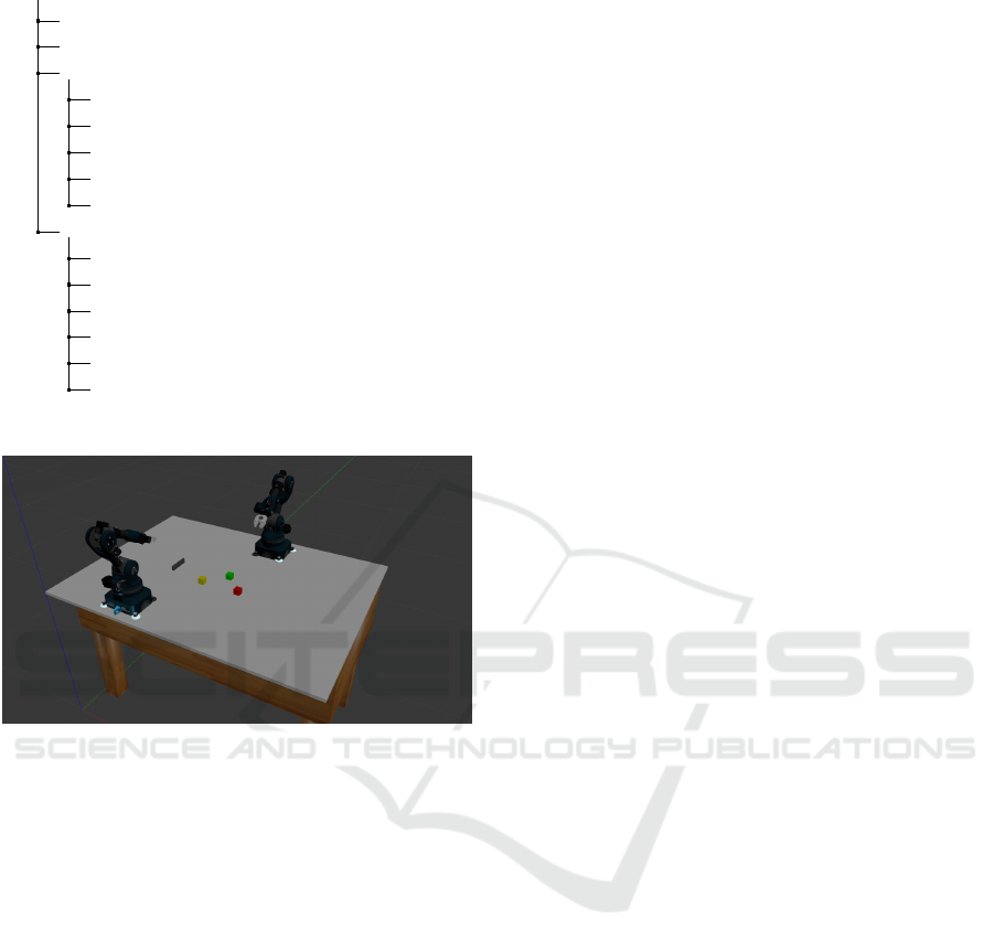
Figure 6: XIVT Robotics Demonstrator.
two desktop-sized robotic arms, each mounted at one
of twelve pre-defined spots on a table plate, leading
to a total of 80 different positioning variants. Each
robotic arm can be equipped with one of five different
tools, i.e., three types of grippers, an electromagnet
and a suction cup. Fig. 6 shows a screenshot of a
simulation of the demonstrator.
Based on this setup we performed a case study in
which we modelled the individual components and
the overall setup. Parts of the resulting model are
shown in figures 2 and 3. We then generated the
respective ROS packages for simulation and motion
planning as shown in figures 4 and 5. Finally, we
used the generated packages to implement and simu-
late two pick-and-place scenarios in which one robot
picks up an object from the table and hands it over
to the other robot which then places it back on the
table. In the first scenario, the robots’ behavior is im-
plemented based on the low-level joint trajectory con-
trollers. In this case, the program code needs to be ad-
justed according to the robot positions. In the second
scenario, the robots use the generated MoveIt config-
uration for motion planning in order to perform the
handover regardless of their positioning on the table.
The robot model used in the demonstrator is the
Niryo One by the French manufacturer Niryo, who
also provides open-source ROS packages for pro-
gramming and simulation. We used these packages
as a reference to structure our model and successfully
checked the generated packages for correctness and
completeness.
Using MoveIt with a newly configured robot usu-
ally requires going through a 12-step setup assistant.
Included in these 12 steps are the configuration of
named robot poses, passive joints and sensor configu-
ration (steps 5, 7 and 8), which were not taken into
consideration, as they are not part of the use case.
These would still have to be performed by the setup
assistant, if desired. Using the generated packages,
we were able to reduce the remaining nine steps to a
single step, i.e., generating the self-collision matrix,
which is recommended but not required to perform.
In summary, the generated packages reduce the re-
quired manual configuration significantly and can en-
tirely eliminate it in simple cases.
7 CONCLUSION AND FUTURE
WORK
In this paper we presented a model-driven engineer-
ing methodology to describe and simulate ROS-based
robots using a UML profile and code generation. We
successfully applied the methodology to a small use
case example and found it to be usable and useful in
order to handle complexity through modularization,
automation and formalization. The support for graph-
ical editing in Papyrus, reduction of manual coding
and automatic default configuration were particularly
helpful. In view of more complex use cases, mainte-
nance of large diagrams can of course be an issue. We
expect this to be mitigated through the modularization
entailed by component-based architectures.
As stated previously, we see our work as com-
plementary to existing MDE approaches mainly di-
rected at behavioral modelling. Hence we see inte-
gration with such solutions, in particular Papyrus for
Robotics, as a promising direction for future work.
Another worthwhile effort is to facilitate the adoption
of model-driven approaches by integrating them with
state-of-practice engineering tools. In this regard we
are currently working on an export of our models to
the Computer Aided Engineering Exchange (CAEX)
and AutomationML format, a data exchange format
commonly used in industry.
Model-driven Engineering and Simulation of Industrial Robots with ROS
269

ACKNOWLEDGEMENTS
This work is funded by the ITEA3 project eXcellence
in Variant Testing (XIVT). See also https://itea4.org/
project/xivt.html.
REFERENCES
Awad, R., Heppner, G., Roennau, A., and Bordignon, M.
(2016). ROS engineering workbench based on seman-
tically enriched app models for improved reusabil-
ity. In 2016 IEEE 21st International Conference
on Emerging Technologies and Factory Automation
(ETFA), pages 1–9.
Bruyninckx, H., Klotzbücher, M., Hochgeschwender, N.,
Kraetzschmar, G., Gherardi, L., and Brugali, D.
(2013). The BRICS component model: a model-based
development paradigm for complex robotics software
systems. In Proceedings of the 28th Annual ACM
Symposium on Applied Computing, SAC ’13, pages
1758–1764, New York, NY, USA. Association for
Computing Machinery.
Bubeck, A., Weisshardt, F., and Verl, A. (2014). BRIDE - A
toolchain for framework-independent development of
industrial service robot applications. In ISR/Robotik
2014; 41st International Symposium on Robotics,
pages 1–6.
Chitta, S., Marder-Eppstein, E., Meeussen, W., Pradeep, V.,
Rodríguez Tsouroukdissian, A., Bohren, J., Coleman,
D., Magyar, B., Raiola, G., Lüdtke, M., and Fernan-
dez Perdomo, E. (2017). ros_control: A generic and
simple control framework for ROS. The Journal of
Open Source Software, 2(20):456.
Coleman, D., Sucan, I., Chitta, S., and Correll, N. (2014).
Reducing the Barrier to Entry of Complex Robotic
Software: a MoveIt! Case Study. arXiv:1404.3785
[cs]. Publisher: Università degli studi di Bergamo.
Estefo, P., Robbes, R., and Fabry, J. (2015). Code dupli-
cation in ROS launchfiles. In 2015 34th International
Conference of the Chilean Computer Science Society
(SCCC), pages 1–6, Santiago, Chile. IEEE.
Hammoudeh Garcia, N., Lüdtke, M., Kortik, S., Kahl, B.,
and Bordignon, M. (2019). Bootstrapping MDE De-
velopment from ROS Manual Code - Part 1: Meta-
modeling. In 2019 Third IEEE International Confer-
ence on Robotic Computing (IRC), pages 329–336.
Hammoudeh García, N., Deshpande, H., Santos, A., Kahl,
B., and Bordignon, M. (2021). Bootstrapping MDE
development from ROS manual code: Part 2—Model
generation and leveraging models at runtime. Soft-
ware and Systems Modeling.
Koenig, N. and Howard, A. (2004). Design and use
paradigms for Gazebo, an open-source multi-robot
simulator. In 2004 IEEE/RSJ International Confer-
ence on Intelligent Robots and Systems (IROS) (IEEE
Cat. No.04CH37566), volume 3, pages 2149–2154
vol.3.
Schlegel, C. and Worz, R. (1999). The software frame-
work SMARTSOFT for implementing sensorimotor
systems. In Proceedings 1999 IEEE/RSJ Interna-
tional Conference on Intelligent Robots and Sys-
tems. Human and Environment Friendly Robots with
High Intelligence and Emotional Quotients (Cat.
No.99CH36289), volume 3, pages 1610–1616 vol.3.
Schlingloff, H., Kruse, P. M., and Saadatmand, M. (2020).
Excellence in variant testing. In Proceedings of the
14th International Working Conference on Variabil-
ity Modelling of Software-Intensive Systems, VAMOS
’20, pages 1–2, New York, NY, USA. Association for
Computing Machinery.
Stampfer, D., Lotz, A., Lutz, M., and Schlegel, C. (2016).
The SmartMDSD Toolchain: An Integrated MDSD
Workflow and Integrated Development Environment
(IDE) for Robotics Software. Journal of Software En-
gineering for Robotics, page 18.
The Object Management Group (2012). Robotic Technol-
ogy Component (RTC).
The Object Management Group (2016). Hardware Abstrac-
tion Layer for Robotic Technology, v1.0 Beta.
Zamalloa, I., Muguruza, I., Hernández, A., Kojcev, R., and
Mayoral, V. (2018). An information model for mod-
ular robots: the Hardware Robot Information Model
(HRIM). arXiv:1802.01459 [cs]. arXiv: 1802.01459.
MODELSWARD 2022 - 10th International Conference on Model-Driven Engineering and Software Development
270
