
Classification Scheme for the Concrete Syntax of Graph-like
Modeling Languages for Layout Algorithm Reuse
Gregor Wrobel
a
and Robert Scheffler
b
Graph Based Engineering Systems, Society for the Advancement of Applied Computer Science,
Volmerstraße 3, Berlin, Germany
Keywords: Concrete Syntax of Modeling Languages, Graph-like Modeling Languages, Graph-drawing, Layout
Algorithm, Domain-Specific Modeling.
Abstract: Graph-like modeling languages (GLML) are deployed in various domains. In model-based software
engineering they are used directly or indirectly for the development of software. In different engineering
systems, graph-like models are artifacts (circuit diagrams, energy flow diagrams) of the respective domain,
which serve as input for downstream specialized applications (simulators, optimizers). When developing
modeling tools, the concrete syntax of a language for creating, editing, and understanding models is
immensely important. In order to develop tools with good usability, layout algorithms for the used languages
have to be integrated. The development of these layout algorithms is particularly complex. With graph
drawing there is a specialized field that deals with the development of layout algorithms for graphs. Some of
these algorithms can be used for the layout of GLML or be adapted for GLML. In order to allow the reuse of
layout algorithms and their assignment to a certain class of GLML, a classification scheme for the concrete
syntax for GLML is presented in this paper.
1 INTRODUCTION
Abstract models and modeling languages are used in
software engineering and classical engineering
sciences to describe systems. Graph-like languages
were introduced as suitable modeling tools as early as
the turn of the 20
th
century. Many inventions in the
field of electricity were published in patent
specifications using graph-like visualizations e.g.,
(Tesla, 1901). The prevalence of computer
technology and especially the propagation of model-
based design (MBD) have increasingly led to the rise
of GLML in the sciences.
The concrete syntax of a language is of utmost
importance for the understanding of the language
(Karsai et al., 2009). In this context, the
comprehensibility of modeling languages strongly
depends on the modeling skills of the users. The users
deploying model based software development
(MBSD) are typically software engineers with
experience in abstract languages (e.g., programming
languages) and general purpose modeling languages
a
https://orcid.org/0000-0003-4234-0794
b
https://orcid.org/0000-0002-3015-0099
(GPML) like UML. In model based engineering
(MBE) the users are often classical engineers with
little modeling experience. They are supported by
domain-specific languages (DSL).
Another important aspect is the usage of the
created models. Applications that only need a single
model to be generated do not have high demands on
the usability of the modeling process. But when
models are created and edited frequently, the
modeling itself becomes an important part of the
user’s work. This is then linked to high demands
regarding usability, comparable to the demands of
UI/UX design.
To meet these requirements, modeling tools have
to offer algorithms both for drawing of and
interacting with the GLML.
The layout of GLML is complex compared to the
concrete syntax of textual languages. Although graph
drawing is the specialized field that is concerned with
the visualization of graphs, it has not systematically
been applied in MBD yet (Binucci et al., 2019). There
are two reasons for this. On the one hand, the
344
Wrobel, G. and Scheffler, R.
Classification Scheme for the Concrete Syntax of Graph-like Modeling Languages for Layout Algorithm Reuse.
DOI: 10.5220/0010913400003119
In Proceedings of the 10th International Conference on Model-Driven Engineering and Software Development (MODELSWARD 2022), pages 344-351
ISBN: 978-989-758-550-0; ISSN: 2184-4348
Copyright
c
2022 by SCITEPRESS – Science and Technology Publications, Lda. All rights reserved
automatic drawing of graphs is less important than the
implementation of layout algorithms and interaction
methods that support the creating and editing of
models. Here aspects such as dynamic graph drawing
and layout stability are more important than static
graph drawing. On the other hand, graphical models
within the scope of MBD are structurally very varied.
They differ from the classic, simple graph model
consisting of vertices and edges. Graph models in
MBD can be port graphs, hyper graphs, nested
graphs, and labeled graphs. In this paper, these
models are encapsulated in the term graph-like.
The multitude of different graph models, which
are often defined in the concrete syntax of the
metamodels for GLML, and the different use cases
for layout procedures complicate their reuse and
adaptation considerably. Reuse and compatibility (of
languages) are two of the TOP 10 challenges faced in
MDE artifact sharing (Damasceno and Strüber,
2021). Typical artifacts in MDE include models,
metamodels, model transformations, and modeling
tools. In addition, for widely used languages,
especially GPML, the concrete syntax is defined only
very superficially, even though it should be an
important part of the language. For UML 2.5.1, the
specification takes up just 20 of 754 pages of
documentation (OMG UML 2.5.1). A major
shortcoming is that for many languages there is de-
facto no sufficient definition of the concrete syntax to
provide state-of-the-art layout algorithms.
This paper presents a classification scheme for the
concrete syntax of GLML. This provides the
possibility to assign layout algorithms not to a
specific language or tool, but to a class of modeling
languages according to the classification scheme. A
classifier provides developers with the ability to more
effectively use existing layout procedures, which may
be grouped in libraries (e.g. the Eclipse Layout
Kernel (Eclipse Foundation, 2021)), for the layouting
of GLML. In particular, if layout procedures can be
used via parameters for the layout of different
concrete syntaxes, classifiers enable the mapping
between GLML and layout procedures. This
facilitates the reuse and adaptation of layout
algorithms and greatly simplifies tool development.
The proposed classification scheme does not
claim to be exhaustive. It will be continuously
extended in further work.
Chapter 2 of the paper presents a metamodel for
GLML. The metamodel describes the essential model
elements, for which features are listed in the
1
In the metamodel in Figure 1, edges must always be
connected to ports. To use this metamodel to represent a
graph model without ports, each node is assigned exactly
classification scheme. In chapter 3, the classification
scheme is detailed. Using the examples of the
classical graph model, a GPML, and a DSL, Chapter
4 applies the classification scheme and assigns
corresponding layout algorithms. Chapter 5 describes
the state of the art and Chapter 6 gives a short outlook
on further work.
2 FEATURES AND METAMODEL
OF GLML
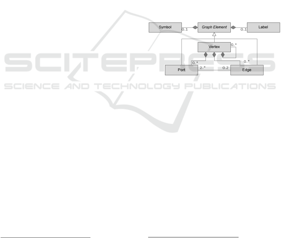
Figure 1 shows a possible metamodel for GLML. The
essential model elements are nodes, ports, edges,
labels, and symbols. Nodes, ports and edges have a
graphical expression (symbol) and thus reflect
domain-specific semantics. This makes the model
elements distinguishable and recognizable. The
symbols are irrelevant for layout procedures and are
not part of the classification scheme.
Figure 1: A metamodel for GLML.
Compared to the "classical" graph model, GLML
differ in particular in that the edges do not directly
connect the nodes and the connection is made via
ports that are located on the nodes.
1
Ports for connecting nodes are used in many
graphical languages. On the one hand, ports can be
specified explicitly, and they can have a graphical or
textual form, for example with fixed ports in ladder
diagrams and function block diagrams in IEC 61131-
3. On the other hand, ports can also be used to specify
connection positions of edges to nodes. These ports
can have no expression and would then not be
recognized as such in the graphical representation.
Nodes are nested in some graphical modeling
languages. They in turn contain nodes and edges and
can also be connected to them via edges (e.g., UML
activity diagrams).
The main classification features for edges are the
number of possible edge connections, specifications
one port that has no symbol and is located in the center of
the node.
Classification Scheme for the Concrete Syntax of Graph-like Modeling Languages for Layout Algorithm Reuse
345

for routing of the edges (straight or orthogonal), and
the distinction between directed and undirected
edges. On the one hand, hyperedges can be used to
visualize the real properties of technical networks,
e.g., power grids, and thus to better understand them
(Wrobel et al., 2021). On the other hand, hyperedges
increase the clarity of, e.g., UML diagrams (Purchase
et al., 2001). A language where edges can only be
associated with one port is, e.g., IDEF0 (Menzel and
Mayer, 2006; IDEF, 2021).
2
Labels describe the other elements in more detail
and make them distinguishable and recognizable.
Ports must be distinguished from each other, e.g. to
ensure that they are connected to valid edges (e.g., in
circuit diagrams according to EN 60617-2).
3 CLASSIFICATION SCHEME
Chapter 3 provides a classification scheme for
GLML. The first subchapter introduces the notation
of the scheme and the following subchapters describe
the classifiers for nodes, ports and edges of GLML.
3.1 Notation
The notation of the classification scheme is based on
a classification for assembly line balancing problems
(Boysen et al., 2007)
3
. The concrete syntax of a
GLML is described by a 3-tuple
𝜶|𝜷|𝜸
, where α, β,
and γ are vectors. The vectors
describe the classificators for vertices (α), ports (β),
and edges (γ). The description of the classifiers is in
terms of vectors, because GLML can have different
vertex types (α
i
), port types (β
j
), and edge types (γ
k
).
Each type is described by a set of classifiers, so
that:
1234
,,,
iiiii
for each vertex type,
2
Using the metamodel from Figure 1 to visually represent
edges connected only by a port, a symbolless pseudo node
with a symbolless port must be created.
3
A communality between assembly line balancing
problems and the layouting of GLML is that although
there is a family of related tasks, the concrete use cases of
these tasks differ concerning parameters and constraints.
12345
,,,,
j jjjjj
for each port type, and
1234
,,,
kkkkk
for each edge type.
To keep the classifiers as short as possible, default
classifiers are marked with the symbol ο in the
classification scheme, as in (Boysen et al., 2007).
These can be omitted when using the classifiers.
An asterisk (∗ ) after a classifier means that a
subset (without ο) of the specified classifiers is used
for classification; without the ∗, exactly one classifier
applies.
All classifiers are unique so that their feature
assignment can be omitted.
3.2 Vertex Classification
Nesting Restriction
1
,
ii
nested
1
i
Non-nested vertices.
1
ii
nested Nested vertices.
Orientation Restriction
2
,,
a
iii
rot ref
2
i
No rotation or mirroring allowed.
2
ii
rot
Rotation of the vertex by degree φ:
4
φ= ο; no rotation (φ=0°),
φ; rotation to the horizontal.
2 a
ii
ref
Mirroring of the vertex allowed:
a = h; horizontal mirroring
allowed,
a = v; vertical mirroring allowed,
a = hv; horizontal and vertical
mirroring allowed.
Label Position
3
,_ ,_
iii
l free l ref
3
i
No vertex label.
3
_
ii
lfree
Arbitrary placement of labels.
3
_
i
lref
Placement of labels is fixed.
Label Orientation
4
,_ ,_
iii
lrotlref
4
i
No rotation or mirroring allowed.
4
_
ii
lrot
Rotation of the label by degree φ:
φ= ο; no rotation (φ=0°),
φ; rotation to the horizontal.
4
_
ii
lref
Mirroring of the label allowed.
5
As a result, many algorithms exist and it is difficult for
developers to assign existing procedures to a concrete
task (reuse).
4
Angles are always assumed to be positive clockwise.
5
This does not mean mirrored writing, but rather “readable
from below/top“.
,,
1
11
j
ik
ln
m
MODELSWARD 2022 - 10th International Conference on Model-Driven Engineering and Software Development
346

3.3 Port Classification
Position Classification
1
,,,
d
jjjj
f
ree side fixed
1
j
No ports. As in the classical graph
model, nodes are directly connected
via edges.
1
jj
f
ree
Ports can be arbitrarily placed on the
shape of a vertex.
1 d
jj
s
ide
Ports can be assigned to specific sides
of the vertex shape. Ports can then be
freely placed on their assigned side.
The sides are defined by the directions
,,,d north south east west
,
d = north; top side,
d = south; bottom side,
d = east; right side,
d = west; left side.
Ports can be assigned to multiple
allowed sides by enumerating the
directions (comma separated).
1
jj
f
ixed
Ports have a fixed position on the
vertex shape.
Connection Number
2
,
q
jj
n
2
j
Exactly one edge allowed.
2 q
jj
n
Ports can connect to n edges. The
qualifier q specifies:
m = ο; exact number,
m = max; maximum number,
m = min; minimum number.
Port Direction
3
,,
jjj
in out
3
j
No port direction.
3
jj
in
Input port.
3
jj
out
Output port.
3 d
jj
con
Connection port on nested vertices.
The direction of the edges connected
on this port is classified by:
d= ο; No port direction.
d=in-out; Input port from outside and
output port from inside.
6
An extension of the classifier so that a fixed, maximum
or minimum number of edge connections is specified is
conceivable. However, the authors do not know of any
graphical language that meets these criteria at this time.
7
So-called k-linear maps (cf. Nickel and Nöllenburg
(2019) occur mainly in transportation maps, and the
d=out-in; Output port from outside and
input port from inside.
Label Position
4
,_ ,_
jjj
l free l ref
4
i
No port label.
4
_
ii
lfree
Arbitrary placement of labels.
4
_
i
lref
Placement of labels is fixed.
Label Orientation
5
,_ ,_
jjj
lrotlref
5
i
No rotation or mirroring allowed.
5
_
jj
lrot
Rotation of the label by degree φ:
φ= ο; no rotation (φ=0°).
5
_
jj
lref
Label can be mirrored.
3.4 Edge Classification
Structure
1
,,
m
kkk
hyper one
1
k
Port to port connection. An edge is
connected to exactly two ports.
1 m
kk
hyper
An edge can connect to multiple ports.
The multiplicity of ports is specified
as m with
,m1toN
.
6
m = ο; m to n relation.
m = 1toN; 1 to n relation.
A 1 to n relation implies, that the edge
is directed (
2
kk
dir
) and either
source or sink are connected to a
single port.
1
kk
one
Edge is connected to exactly one port.
Routing
2,
,, ,
f
kkkk
ort k lin poly
2
k
Straight routing without bends.
2
kk
ort
Orthogonal routing, only horizontal or
vertical line segments.
2,f
kk
klin
Routing of line segments whose
angles to each other have an integer
multiple of 360°/2k, for example:
7
f=2; orthogonal,
8
f=3; hexalinear,
f=4; octolinear.
The rotation angle of the routing
relative to the horizontal is φ.
octolinear routing
24
kk
klin
is the de-facto
standard for such diagrams (cf. Wu et al. (2020)).
8
22
kk
ort k lin
; For orthogonal routing, a special
classifier
2
k
k
ort
is introduced to highlight one of the
most widely used classifiers.
Classification Scheme for the Concrete Syntax of Graph-like Modeling Languages for Layout Algorithm Reuse
347

φ=○; no rotation to the horizontal.
φ; rotation to the horizontal.
2
kk
poly
Routing with Polylines.
2
kk
arc
Routing with arcs.
Label Position
3
,_ ,_
kkk
l free l ref
3
k
No edge label.
3
_
kk
lfree
Arbitrary placement of labels.
3
_
k
lref
Placement of labels is fixed.
Label Orientation
4
,_ ,_
kkk
lrotlref
4
k
No rotation or mirroring allowed.
4
_
kk
lrot
Rotation of the label by degree φ:
φ=○; no rotation (φ=0°).
4
_
kk
lref
Label can be mirrored.
4 EXAMPLES
In this section, the classification scheme presented for
the concrete syntax is applied to three examples, a
simple graph model, the UML diagram from Figure
1, and a DSL. For the second example, the description
of the classification is more detailed.
4.1 Simple Graph Model
For the simple graph model consisting of nodes,
(undirected) edges, and no labels, the classification
tuple is
||
or
||
for short.
Figure 2 shows the famous Königsberg bridge
problem (Euler, 1735): The vertices A, B, C, and D
represent the disctricts and the edges represent the
seven bridges of Königsberg, drawn as a graph
according to the classification ( | | ).
Figure 2: Graph model of the Königsberg bridge problem.
4.2 UML Class Diagram
The UML is very vague in defining the concrete
syntax for diagrams. Tool developers are tasked with
defining a concrete syntax for diagrams and
implementing it in software tools via layout
algorithms. The UML class diagram in Figure 1 will
be used as an example with the following concrete
syntax:
1. Classes should be arranged in such a way that
the inheritance hierarchy is taken into account.
2. Hyperedges are to be used for the inheritance
relationships.
3. All edges must be routed orthogonally.
4. The ports for the inheritance relationship must
be arranged in such a way that the ports on the
base classes are placed on the lower outer
border and the ports for the derived classes are
placed on the upper outer border of vertices.
5. All other ports can be placed freely.
6. Ports of aggregation and association relations
have labels (describing the multiplicities).
7. All ports are supposed to be evenly distributed
on the outer contour of a node.
This results in the following classifier of vertices,
ports and edges for the UML diagram in Figure 1:
Vertices: Because the example UML class diagram
has only one type of vertex (class), the default
features apply, so that
.
Ports can be separated into 5 types:
1. Ports of the base classes to which the edges for
the inheritance relation are connected have the
following classifier:
111
;
south
s
ide in
.
2. Ports of the derived classes to which the edges
for the inheritance relation are connected have
the following classifier:
222
;
north
s
ide out
.
3. Ports of the owning classes to which edges for
the aggregation relation are connected have
the classifier:
333 3
;;_
f
ree in l free
.
4. Ports of the not owning classes to which edges
for the aggregation relation are connected
have the classifier:
4444
_;;
f
ree out l free
.
5. Ports for association relations are classified
with
55 5
;_
f
ree l free
.
Edges can be separated into 3 types:
1. Edges for inheritance relations are orthogonal
hyperedges. Their classifier is
;
1toN
111
hyper ort
.
2. Edges for aggregation relations are port-to-
port connections to be routed orthogonally.
Their classifier is
22
ort
.
MODELSWARD 2022 - 10th International Conference on Model-Driven Engineering and Software Development
348
3. Edges for association relations have the same
classifier as aggregation relations:
33
ort
.
This results in the following classification of the
concrete syntax for the UML diagram in Figure 1:
This classification for a concrete syntax for UML
class diagrams can be used to develop suitable layout
algorithms or to reuse or adapt existing algorithms.
For example, a static automatic layout for this
graphical language is provided in (Eiglsperger, 2003),
whereas (Helmke et al., 2021) provide dynamic
layout support for orthogonally routed hyperedges
;
1toN
hyper ort
with topological stability.
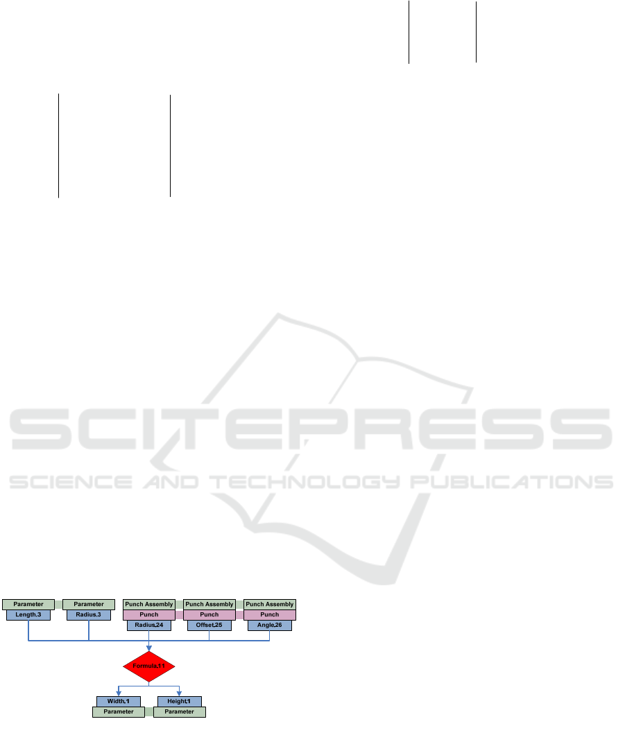
4.3 Parameter Map of CAD-Model
The third example is the concrete syntax of a DSL.
The model in Figure 3 represents the parametric
relationships of a 3D-CAD model of a deep drawing
tool. The vertices represent the elements of the CAD
model and their hierarchical structure. Identical
model components are represented by a thick
connection (e.g., the green connection between the
occurrences of “punch assembly” in Figure 3). The
central vertex of the parameter map represents a
specific parametric relationship (here a formula)
between input variables (top) and output variables
(bottom) (Scheffler et al., 2016).
Figure 3: Parameter map of a parametric 3D-CAD model
for deep drawing tools (Scheffler et al., 2016).
The concrete syntax of the DSL can be described
by the following classifier:
All vertices have the default properties of the
classifier.
There are three types of ports. One type for the
identity relationship (index 1) with fixed positions
and two types for the input ports (index 2) and for the
output ports (index 3) to connect directed edges
between parameter nodes and formula.
In accord with the definition of ports, there are
two types of edges. The edges that map the identity
relationship have the default properties
11
. The
edges between parameter nodes and formula nodes
are directed hyperedges that are routed orthogonally:
;
1toN
222
hyper ort
.
5 RELATED WORK
The concrete syntax of a modeling language is the
interface to the modeler. It is thus important for the
usability of the language (Karsai et al., 2009), and
building editors is a particular challenge for
developers (Völter et al., 2013). Their proximity to
graphs and the requirements to develop layout
algorithms for languages suggest a consideration of
graph-drawing.
Graph-drawing methods exist for different classes
of graphs. In (Di Battista et al., 1999) a general
framework for graph drawing is presented, which
contains parts of the features of the presented
classification scheme (e.g., port/edge direction
3
and routing classification
3
). However, the
framework is strongly focused on concrete layout
aspects (planarity) and properties of graphs
(connectivity). Ports, nested graphs, hypergraphs, and
labeling are not included in this framework.
For port graphs, an important feature, the port
position
2
, is classified as part of the development
of layout methods (Schulze et al., 2014).
Problems of labeling were researched intensively
in the environment of geographic maps. In (Poon et
al., 2004) a model with 9 different possibilities for the
placement of axis-parallel enveloping label
rectangles is presented. An overview of publications
on map labeling is provided by (Wolff, 2009).
Label orientation is also a relevant and widely
researched topic in traffic maps. An overview of
existing work is provided by (Wu et al., 2020).
;
;
;
1
1
22
1toN
22
33
fixed
fixed in
hyper ort
fixed out
;
;
;
;;_
;;_
;_
south
11
1toN
north
11
22
2
33 3
3
44 4
55
side in
hyper ort
side out
ort
free in l free
ort
free out l free
free l free
Classification Scheme for the Concrete Syntax of Graph-like Modeling Languages for Layout Algorithm Reuse
349

Graph drawing represents only one side of the
related work: the possible layout procedures for
graphical languages to be used in graphical editors.
Originating from model driven development (MDD),
so-called language workbenches are also to be
considered. In language workbenches, the abstract
and the concrete syntax as well as the mapping
between them is defined as a metamodel (MetaEdit+,
2021; Microsoft DSL, 2021, 2021; OBEO, 2021;
Sirius, 2021; GMF, 2021) and graphical editors for
DSLs are generated from it. This is where the
challenges arise regarding the development of
suitable layout algorithms, which are currently not
always well solved for practical applications (Cooper
et al., 2021).
Furthermore, there are some languages, especially
technical languages, for which the concrete syntax is
very precisely defined. These are mainly established
modeling languages from engineering science. Their
concrete syntax is more precisely specified, e.g., in
the form of a standard (USAS Y14.15-1966; IDEF,
2021).
The presented classification scheme distinguishes
nodes, ports, edges, labels, and symbols as the most
important model elements. These model elements are
explicitly included in several metamodels (Pleßow
and Simeonov, 1989; Wrobel et al., 2007; Barzdins
and Kalnins, 2016; Eclipse Foundation, 2021), but the
authors are not aware of any classification scheme for
the concrete syntax of GLML.
6 CONCLUSION AND FURTHER
WORK
Layout is an important component of the usability of
a GLML. Good layout algorithms enable even users
with limited modeling experience to build, modify,
and understand complex models. GLML appear in the
form of both GPML and DSL. They are important
artifacts in MBD tools and technical engineering
tools. For graphs, there are very many layout methods
that have been adapted for GLML, especially for
static drawings. The large variety of structurally
different GLML makes the development, reuse, and
adaptation of graph drawing algorithms very costly
for tool developers. In modeling tools, dynamic
layout algorithms are of greater importance compared
to static layout algorithms, although their
development is underrepresented in graph drawing.
9
The DSL in the example of chapter 4.3 is a GLML that
is automatically generated to show relations inside a 3D-
CAD model.
With the developed approach for the classification
of concrete syntax, the presented classification
scheme offers the possibility to better relate GLML
and layout methods. This facilitates tool development
for MDD. It is an important contribution to the reuse
of layout algorithms and intra-language compatibility
of GLML, one of the current challenges in MDE.
The presented classification will be continuously
extended in further work. Aspects of automatic node
placement, for which there are a number of classical
static graph drawing methods and adaptations for
GLML, are currently not present in the classifier. In
particular, for GLML where model visualization
rather than model building is the focus of a tool,
9
the
inclusion of placement can be valuable.
Furthermore, model-to-model transformations
between GLML with distinct classifiers are to be
investigated. With the help of these model-to-model
transformations, layout methods of another class can
be reused for a GLML. Further possible next steps
would be to classify existing languages (e.g., GPML)
and layout methods according to the presented
features in order to facilitate mutual mapping.
ACKNOWLEDGEMENTS
The authors thank the German Research Foundation
(DFG) for the financial support of the research project
“Method for the Model-Driven Design of Deep
Drawing Tools” (project number BA 6300/1-3).
REFERENCES
Barzdins J, Kalnins A. (2016) Metamodel Specialization
for Graphical Language and Editor Definition. BJMC;
4(4): 910–33.
Binucci C, Brandes U, Dwyer T et al. (2019) 10 Reasons to
Get Interested in Graph Drawing. In Steffen B,
Woeginger G, editors. Computing and Software
Science. Cham: Springer International Publishing.
p. 85–104. ISBN 978-3-319-91907-2.
Boysen N, Fliedner M, Scholl A. (2007) A classification of
assembly line balancing problems. European Journal of
Operational Research; 183(2): 674–93.
Cooper J, La Vega A de, Paige RF et al. (2021) Model-
Based Development of Engine Control Systems:
Experiences and Lessons Learnt. In ACM/IEEE 24th
International Conference on Model Driven
Engineering Languages and Systems.
MODELSWARD 2022 - 10th International Conference on Model-Driven Engineering and Software Development
350

Damasceno CDN, Strüber D. (2021) Quality Guidelines for
Research Artifacts in Model-Driven Engineering.
Di Battista G, Eades P, Tamassia R et al. (1999) Graph
drawing: Algorithms for the visualization of graphs.
Upper Saddle River, NJ: Prentice Hall. ISBN
0133016153.
Eclipse Foundation. (2021) Eclipse Layout Kernel: Graph
Data Structure. Available from: URL:
https://www.eclipse.org/elk/ (accessed 31 Oct 2021).
Eiglsperger M. (2003) Automatic layout of UML class
diagrams. Tübingen, Univ., Diss., 2003. Tübingen.
EN 60617-2. (1997). EN 60617-2. Graphical symbols for
diagrams.
Euler L. (1735) Solutio problematis ad geometriam situs
pertinentis. Commentarii academiae scientiarum
Petropolitanae; (8): 128–40.
GMF. (2021) Graphical Modeling Framework | The Eclipse
Foundation. Available from: URL: https://www.
eclipse.org/modeling/gmp/ (accessed 23 Jul 2021).
Helmke S, Goetze B, Scheffler R et al. (2021) Interactive,
Orthogonal Hyperedge Routing in Schematic Diagrams
Assisted by Layout Automatisms. In Proceedings of the
12th Internation Conference on Theory and Application
of Diagrams. p. 20–7.
IDEF N. (2021) Integrated DEFinition Methods (IDEF):
IDEF Family of Methods. Available from: URL:
https://www.idef.com/ (accessed 11 Oct 2021).
IEC 61131-3. (2014). International Electrotechnical
Commission IEC 61131-3:2013.
Karsai G, Krahn H, Pinkernell C et al. (2009) Design
Guidelines for Domain Specific Languages.
Proceedings of the 9th OOPSLA Workshop on Domain-
Specific Modeling (DSM' 09). Available from: URL:
https://arxiv.org/pdf/1409.2378.
Menzel C, Mayer RJ. (2006) The IDEF Family of
Languages. In Bernus P, Mertins K, Schmidt G, editors.
Handbook on Architectures of Information Systems.
Berlin, Heidelberg: Springer Berlin Heidelberg. p. 215–
49. ISBN 3-540-25472-2.
MetaEdit+. (2021) MetaEdit+ Domain-Specific Modeling
(DSM) environment. Available from: URL:
https://www.metacase.com/products.html (accessed 14
Dec 2021).
Microsoft DSL. (2021) Modeling SDK for Visual Studio -
Domain-Specific Languages. Available from: URL:
https://docs.microsoft.com/en-
us/visualstudio/modeling/modeling-sdk-for-visual-
studio-domain-specific-languages?view=vs-2022
(accessed 14 Dec 2021).
Nickel S, Nöllenburg M. (2019) Towards Data-Driven
Multilinear Metro Maps.
OBEO. (2021) Obeo Designer. Available from: URL:
https://www.obeodesigner.com/en/solutions (accessed
8 Nov 2021).
OMG UML 2.5.1. (2017) Unified Modeling Language,
v2.5.1. Available from: URL: https://www.omg.org/
spec/UML/2.5.1/PDF (accessed 23 Jul 2021).
Pleßow M, Simeonov PL. (1989) Netlike Schematics and
their Structure Description. Workshop on Informatics in
Industrial Automation: 144–63.
Poon S-H, Shin C-S, Strijk T et al. (2004) Labeling Points
with Weights. Algorithmica; 38(2): 341–62.
Purchase HC, Allder J-A, Carrington D. (2001) User
Preference of Graph Layout Aesthetics: A UML Study.
In Goos G, Hartmanis J, van Leeuwen J et al., editors.
Graph Drawing. Berlin, Heidelberg: Springer Berlin
Heidelberg. p. 5–18. ISBN 978-3-540-41554-1.
Scheffler R, Koch S, Wrobel G et al. (2016) Modelling
CAD Models: Method for the Model Driven Design of
CAD Models for Deep Drawing Tools. In 4th
International Conference on Model-Driven
Engineering and Software Development
(MODELSWARD). p. 377–83.
Schulze CD, Spönemann M, Hanxleden R von. (2014)
Drawing layered graphs with port constraints. Journal
of Visual Languages & Computing; 25(2): 89–106.
Sirius. (2021) Sirius Overview. Available from: URL:
https://www.eclipse.org/sirius/overview.html
(accessed 8 Nov 2021).
Tesla N. (1901) Apparatus for the Utilization of Radiant
Energy: Specification; (Patent No. 685,957). Available
from: URL: https://patents.google.com/patent/US6859
57A/en (accessed 5 Jul 2021).
USAS Y14.15-1966. (1966). Y14.15-1966. Electrical and
Electronics Diagrams. New York: The American
Society of Mechanical Engineers.
Völter M, Stahl T, Bettin J et al. (2013) Model-Driven
Software Development: Technology, Engineering,
Management. s.l.: Wiley. ISBN 0470025700.
Wolff A. (2009) The Map-Labeling Bibliography.
Available from: URL: i11www.iti.kit.edu/~awolff/
map-labeling/bibliography/.
Wrobel G, Ebert R-E, Pleßow M. (2007) Graph-Based
Engineering Systems - A Family of Software
Applications and their Underlying Framework.
Electronic Communications of the EASST, Volume 6:
Graph Transformation and Visual Modeling
Techniques 2007; 6.
Wrobel G, Scheffler R, Kehrer T. (2021) Rethinking the
Traditional Design of Meta-Models: Layout Matters for
the Graphical Modeling of Technical Systems. In 2021
ACM/IEEE 24th International Conference on Model
Driven Engineering Languages and Systems
Companion (MODELS-C). p. 351–60.
Wu H-Y, Niedermann B, Takahashi S et al. (2020) A
Survey on Transit Map Layout - from Design, Machine,
and Human Perspectives. Comput Graph Forum; 39(3):
619–46.
Classification Scheme for the Concrete Syntax of Graph-like Modeling Languages for Layout Algorithm Reuse
351
