
Modeling of Power Supply Systems Equipped with Double Two
Wires and Earth Transmission Lines
Yuri Bulatov
1a
, Andrey Kryukov
2,3 b
, Le Van Thao
2c
, Konstantin Suslov
2,4 d
and Tran Duy Hung
5e
1
Department of Energy, Bratsk State University, Bratsk, Russia
2
Department of Power Supply and Electrical Engineering, Irkutsk National Research Technical University, Irkutsk, Russia
3
Department of Transport Electric Power, Irkutsk State Transport University, Irkutsk, Russia
4
Department of Energy, Transbaikal State University, Chita, Russia
5
Military Industrial College, Hanoi, Socialist Republic of Vietnam
Keywords: Power Supply Systems, Coupled Twin and Earth Cables, Modeling.
Abstract: Power supply systems (PSS) of the agro-industrial complex, as well objects located in the areas remote from
the networks of electric power systems, sometimes use electric transmission lines (ETLs) that exploit the
ground as a conducting part. When currents flow in the ground, it causes electrical safety issues. To solve
them, double two wires and earth (TWE) lines can be used. Such lines use special transformers, in which the
voltage vectors of the grounded terminals have an angular shift of 180º. Due to this, there are no currents in
the ground a symmetrical mode. In the context of digitalization of the electric power industry, creating
computer models of such PSSes that adequately simulate stationary modes is of particular relevance. This
paper presents the results of studies aimed at the implementation of computer models of power supply
systems that incorporate double TWE lines. Constructive diagrams of ETLs with double TWE lines are
proposed. Simulation was carried out by means of the Fazonord software package. The simulation results
drew us to the following conclusions: in comparison with a double-circuit ETL, a double TWE line can
significantly reduce the cost of non-ferrous metal; the asymmetrical design of this ETL causes a decrease in
the quality indicators of electricity at its receiving end; in addition, higher power losses are observed; the
double TWE line can be implemented on the basis of two or four single-phase shielded cables.
a
https://orcid.org/0000-0002-3716-5357
b
https://orcid.org/0000-0001-6543-1790
c
https://orcid.org/0000-0001-6543-1790
d
https://orcid.org/0000-0003-0484-2857
e
https://orcid.org/0000-0002-3563-9811
1 INTRODUCTION
In agricultural areas, distribution electrical networks
are of considerable. In order to save non-ferrous
metal, their implementation sometimes implies
construction power lines that use ground as a
conducting part. Such solutions can also be used to
provide electrical energy to objects located in areas
remote from the networks of electric power systems.
A number of works are devoted to solving the
problems of researching power supply systems
equipped with single-wire power lines with earth as
a return wire (Single Wire Earth Return) (SWER).
The article (Helwig and Ahfock, 2013) discusses
the issues of increasing the capacity of these lines. A
solution to a similar problem for rural SWER
networks is presented in (Wolfs, 2005) and (Wolfs et
al., 2007). The paper (Kavi et al., 2016) describes
methods for detecting faults in single-wire
distribution networks. The paper (Brooking et al.,
1992) is devoted to the problems of upgrading SWER
networks. Models for selecting wires in networks with
SWER lines are proposed in (Bakkabulindi et al.,
2013). The results of studies of the influence of
distributed generation on the modes of electrical
networks with SWER lines are given in (Kashem and
Ledwich, 2004) and (Ledwich, 2004).
Bulatov, Y., Kryukov, A., Van Thao, L., Suslov, K. and Hung, T.
Modeling of Power Supply Systems Equipped with Double Two Wires and Earth Transmission Lines.
DOI: 10.5220/0010996500003203
In Proceedings of the 11th International Conference on Smart Cities and Green ICT Systems (SMARTGREENS 2022), pages 23-31
ISBN: 978-989-758-572-2; ISSN: 2184-4968
Copyright
c
2022 by SCITEPRESS – Science and Technology Publications, Lda. All rights reserved
23
An article (Nkom et al., 2019) discusses the
challenges of using SWER lines in rural Africa. The
article (Nkom et. al., 2018) provides a solution to the
problem of narrow-band modeling of single-wire
power lines. When currents flow in the ground,
electrical safety becomes an issue. To solve them,
dual lines “two wires - ground” (TWE) can be built,
which were first considered in the papers (Andreev,
1952) and (Filshtinsky, 1952). The development of
this idea is given in (Buryanina et al., 2005). These
lines use special transformers in which the voltage
vectors of the grounded terminals have an angular
shift of 180º. Due to this, there are no currents in the
ground in a symmetrical mode.
In the context of the electric power industry
digitalization (Vorotnitsky, 2019), the problems of
creating digital models of PSS with double TWE
lines to ensure adequate simulation of stationary
modes acquire a special relevance.
Such models can
be formed on the basis of developments (Zakaryukin
and Kryukov, 2005) implemented in the Fazonord
software product. These developments are based on
the ideas of building models of elements of electric
power systems (EPS) based on phase coordinates; at
the same time, the main power elements of the EPS,
which include electric transmission line and
transformers, are considered as multi-wire or multi-
winding objects and are presented in the form of
lattice equivalent circuits with a fully connected
topology. Based on this approach, methods and
computer technologies have been implemented, the
distinctive features of which are as follows:
• multi-phase, which consists in the possibility
of modeling multi-phase systems (single-phase,
three-phase, four-phase, six-phase and their various
combinations in one network);
• multi-mode, which allows modeling a wide
range of EPS modes: normal and emergency,
asymmetric, non-sinusoidal, limiting in terms of
static aperiodic stability;
• multitasking, providing the possibility of solving
additional problems relevant for practice: determination
of induced voltages on adjacent transmission lines;
calculation of the intensity of electromagnetic fields
created by traction networks; parametric identification
of transmission lines and transformers according to
measurement data; accounting of active elements of the
EPS; modeling of thermal processes during ice melting.
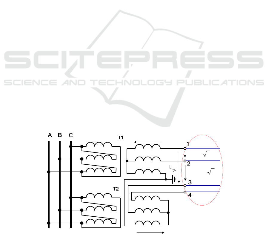
2 DOUBLE TWE LINE
To justify the use of double TWE lines and to
determine their effectiveness, it is necessary to
develop adequate computer models. Since the
double TWE lines are characterized by an
asymmetric structure, it appears reasonable to build
their models on the basis of phase coordinates.
Below are the results of simulating the modes and
electromagnetic fields (Buyakova et al., 2018) of a
double TWE line with a voltage of 35 kV with
respect to the ground, Fig. 1.
The coordinates of the wires of this line with a
length of 5 km with 95 mm
2
aluminium conductor
steel reinforced cables are shown in Fig. 2. To assess
energy efficiency, power quality and
electromagnetic safety conditions, the corresponding
indicators were compared with the results of
simulating the modes and electromagnetic fields
(EMF) of a three-phase power trans-mission line
with 95 mm
2
aluminium conductor steel reinforced
cables, non-standard voltage of 35 kV with respect
to the ground and a line voltage of 60 kV.
F
U
FL
UU 3=
FL
UU 33 =
FL
UU 322 =
I
A
I
B
I
C
I
I
A
I
I
B
II
C
F
U
Figure 1: Schematic diagram of the overhead TWE lines.
SMARTGREENS 2022 - 11th International Conference on Smart Cities and Green ICT Systems
24
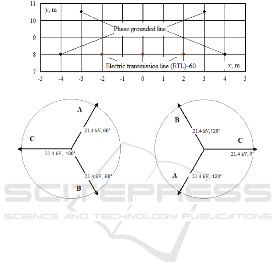
Figure 2: Wires location coordinates.
(a)
(
b
)
Figure 3: Vector voltage diagrams of the phases of the secondary winding of transformers: (a) – T1, the fifth group of
connections; (b) – T2, the eleventh group of connections.
The lack of current in the ground can be illustrated
using vector diagrams of voltages on the secondary
windings of transformers (Fig. 3). These diagrams were
obtained as a result of determining the mode of the
double TWE line without the grounding of phase C.
The mode calculation was carried out with loads of
4 + j3 MV⋅A per phase at the receiving end. Figure 3
shows that for the groups of transformers 5 and 11, the
voltage vectors of the grounded terminals are in
antiphase. This ensures that there are no ground
currents in symmetrical modes.
The results of determining the PSS modes by the
double TWE line show that on the 10 kV side of the
consumer substation, connected at its receiving end and
at the loads indicated above, the voltage asymmetry
factor in the return sequence is 0.8%, and the total
current flowing into the ground is 0.16 А. Dependences
of losses and asymmetry in the electric transmission
line (ETL)-60 and a double TWE line on the
transmitted active power are shown in Figs. 4 and 5.
They were obtained with a power factor of 0.89. The
analysis of these dependences implies that the double
TWE line is characterized by higher losses in
comparison with the ETL-60 (Fig. 4). At the receiving
end of this ETL, a significantly greater asymmetry is
observed. Figures 6 and 7 show the dependences of the
EMF strengths of the double TWE line on the x
coordinate, which is measured from the center of the
line.
Figure 8 shows three-dimensional diagrams of
the strengths of the electric (a) and magnetic (b)
fields created by the double TWE line.
The simulation results draw us to the following
conclusions:
1. In comparison with the ETL of traditional
design, the TWE line has higher losses and voltage
asymmetry at the receiving end;
2. The strengths of the electric field directly
under the wires of the TWE ETL is 33% higher than
the same indicator for the 60 kV ETL;
3. The maximum amplitude of the magnetic field
of the TWE ETL is twice as high as that one of the
60 kV ETL.
Modeling of Power Supply Systems Equipped with Double Two Wires and Earth Transmission Lines
25
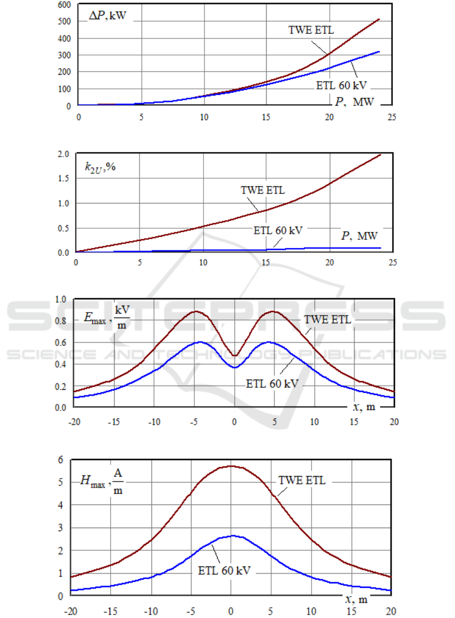
Figure 4: Dependences of active losses in the line on the transmitted power.
Figure 5: Dependencies of the asymmetry coefficient on the transmitted power.
Figure 6: Dependences of the amplitudes of the electric field strengths at the height of 1.8 m on the x coordinate.
Figure 7: Dependences of the amplitudes of the magnetic field strengths at the height of 1.8 m on the x coordinate.
SMARTGREENS 2022 - 11th International Conference on Smart Cities and Green ICT Systems
26
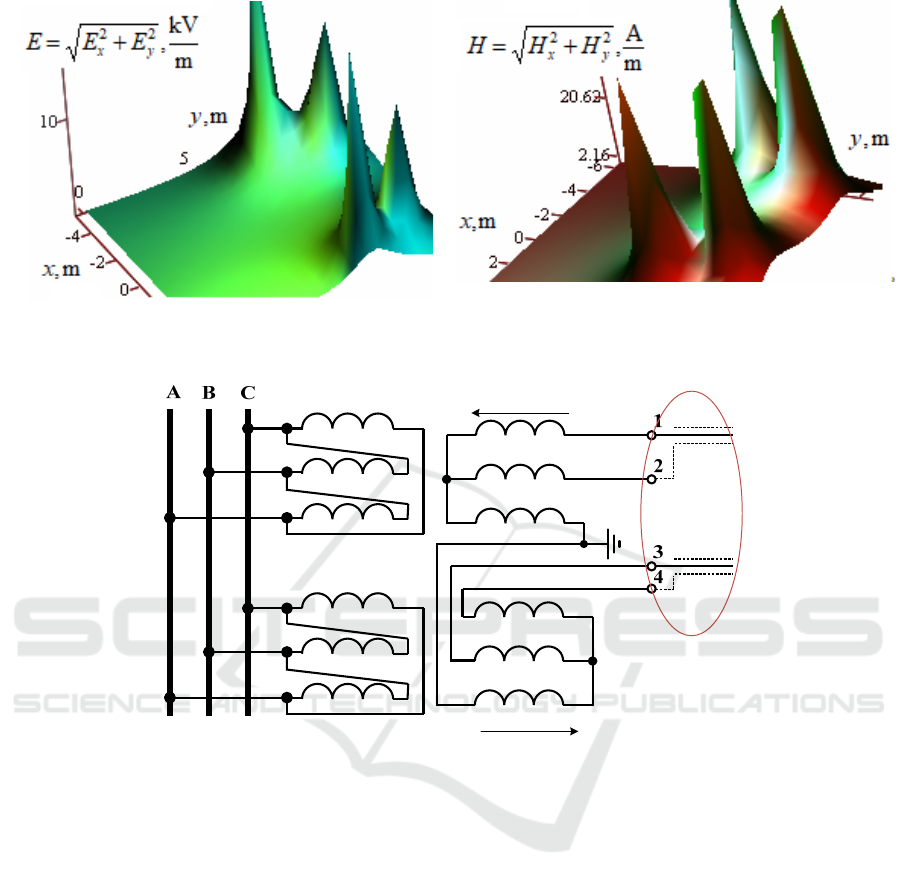
(a) (b)
Figure 8: Volumetric diagrams of electric (a) and magnetic (b) field strengths of the double TWE line.
F
U
I
A
I
B
I
C
I
I
A
I
I
B
II
C
F
U
Figure 9: Schematic diagram of the two-cable TWE line connection.
3 THE TWE LINE BUILD WITH
TWO SPECIAL DESIGN
CABLES
In some cases, when forming a PSS, the use of
overhead electric transmission lines is limited. Such
situations are typical for some settlements, sites of
industrial enterprises, as well as for areas with high
wind loads. In addition, the use of cable TWE lines
can be expedient for the transmission of electricity
by submarine cables to facilities located on the
islands of rivers, lakes, and seas.
Implementation of a double TWE cable line may
use the proposed in (Buyakova et al., 2019)
constructive scheme based on two single-core
shielded cables with molecular cross-linked
polyethylene insulation.
In contrast to the widely used designs, cable
shields for this ETL should ensure that the flow of
currents are proportionate to the currents of the
conductors. In addition, they must have the same
insulation class as the conductors. Such cable lines
can be placed in galleries, overpasses and on other
structures of a similar type. The cable line diagram
(Fig. 9) corresponds to Fig. 1; operating currents of
the cable line flow through the shields. The location
coordinates of the conducting parts of a double cable
line are given in Fig 10. The electrical parameters of
the conductors and shields are the same as in the
above-discussed overhead TWE ETL.
The diagram showing the currents distribution
through the wires of overhead and cable lines is given
in Fig. 11. We can observe some differences in the
currents of conductors and shields of the cable TWE
ETL which is associated with its asymmetric design.
Modeling of Power Supply Systems Equipped with Double Two Wires and Earth Transmission Lines
27
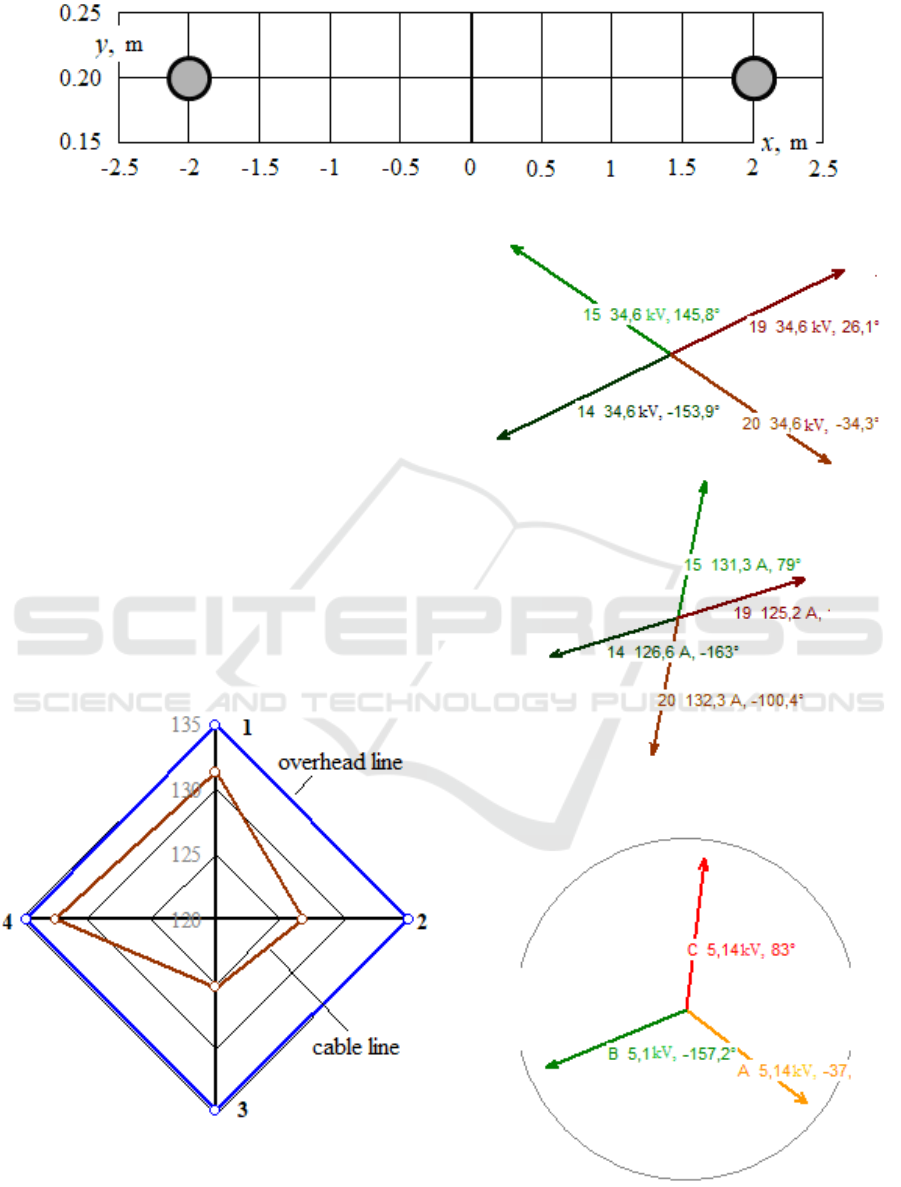
Figure 10: Coordinates of conducting parts.
Vector diagrams characterizing currents and
voltages at the receiving and outgoing ends of the cable
TWE line are shown in Figs. 12 and 13. The input
voltages and currents of cable lines are far from a
symmetrical four-phase system, but the voltages and
load currents on busbars of the 10 kV transformers are
symmetrical with a return sequence voltage asymmetry
coefficient equal to 0.5%.
Figures 14-16 show comparative graphs
characterizing energy efficiency, power quality
indicators for asymmetry and electromagnetic safety of
the considered cable line design in comparison with a
four-wire overhead line.
Compared with the overhead line, the cable TWE
line is characterized by a significantly lower level of
asymmetry (Fig. 15). However, higher magnetic field
strengths are created near the cables. With the same
cross-section of the conducting parts, the active power
losses for overhead lines and cable TWE lines differ
insignificantly (Fig. 14).
Figure 11: Currents in the wires of the overhead line and
cables at the starting ends of the ETL.
Figure 12: Vector diagrams of at the outgoing end of the
cable TWE line.
Figure 13: Vector diagrams of voltages on 10 kV busbars.
SMARTGREENS 2022 - 11th International Conference on Smart Cities and Green ICT Systems
28
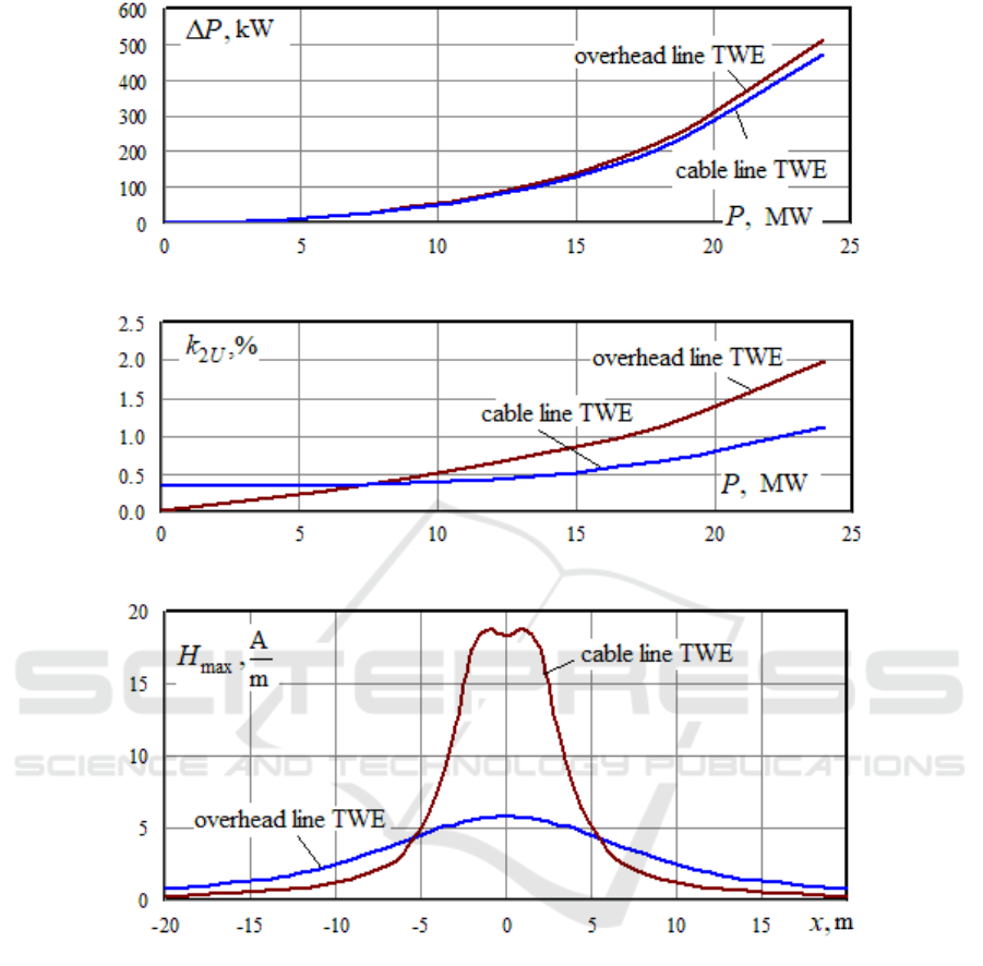
Figure 14: Dependences of losses on the transmitted active power.
Figure 15: Dependences of the return sequence asymmetry coefficient on transmitted power.
Figure 16: Dependences of the amplitudes of the magnetic field strengths at the height of 1.8 m on the x coordinate.
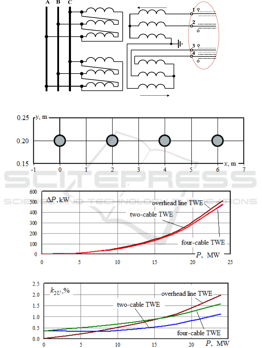
4 THE TWE STRUCTURE BASED
ON FOUR CABLES OF A
STANDARD STRUCTURE
It is possible to consider a scheme of the TWE line
which implementation requires four typical
molecular cross-linked polyethylene cables, Fig. 17.
Its cross-section is shown in Fig. 18.
In simulation, it was assumed that the cable shields
are grounded on one side. At shield currents of 8.2 A,
the total current did not flow through the ground
electrode. Dependences of losses on the transmitted
active power at are shown in Fig. 19 for the following
types of TWE lines: overhead, two-cable, and four-
cable lines. For all types of TWE lines, the losses are
almost the same (Fig. 19). Asymmetry at high
transmitted powers prevails in the double overhead
TWE line. However, at low powers, asymmetry is
greater in the four-cable line, although the asymmetry
coefficient does not exceed 0.5%. The dependences of
the amplitudes of the magnetic field strengths on the x
coordinate are shown in Fig. 21.
Analysis of the simulation results allows us to
conclude that the four-cable TWE line, when
compared to the two-cable one, is characterized by a
higher level of asymmetry and creates a magnetic
field of the same order.
Modeling of Power Supply Systems Equipped with Double Two Wires and Earth Transmission Lines
29
F
U
I
A
I
B
I
C
I
I
A
I
I
B
II
C
F
U
Figure 17: Schematic diagram of the four-cable TWE line connection.
Figure 18: Coordinates of cable locations.
Figure 19: Dependences of losses on transmitted power.
Figure 20: Dependences of the asymmetry coefficient on transmitted power.
SMARTGREENS 2022 - 11th International Conference on Smart Cities and Green ICT Systems
30
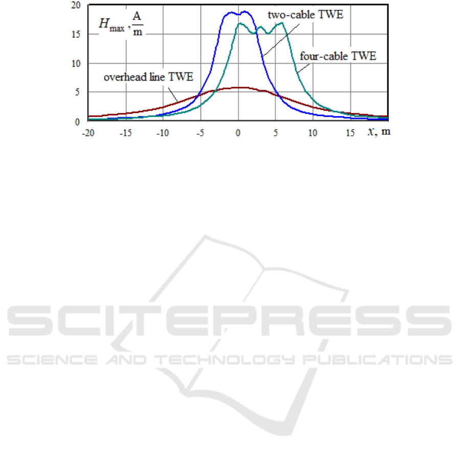
Figure 21: Dependence of the amplitude of the magnetic field strength on the x coordinate.
5 CONCLUSIONS
We proposed a technique that helps adequately
model and simulate double electric two wires and
earth lines. We considered the original designs of
TWE cable lines that can be implemented when the
use of overhead ETLs is limited. Such situations are
typical for some settlements, sites of industrial
enterprises, as well as for areas with high wind
loads. In addition, the use of cable TWE lines may
be appropriate for the transmission of electricity by
submarine cables to facilities located on the islands
of rivers, lakes, and seas.
ACKNOWLEDGEMENTS
The research was carried out within the state
assignment of Ministry of Science and Higher
Education of the Russian Federation (project code:
FZZS-2020-0039).
REFERENCES
Helwig, A., Ahfock, T., 2013. Extending SWER line
capacity, Australasian Universities Power
Engineering Conference (AUPEC), 1-6.
Wolfs, P. J., 2005. Capacity improvements for rural single
wire earth return systems, International Power
Engineering Conference, 1-306.
Wolfs, P.J., Hosseinzadeh, N., Senini, S.T., 2007.
Capacity Enhancement for Aging Distribution
Systems using Single Wire Earth Return, IEEE Power
Engineering Society General Meeting, 1-8.
Kavi, M., Mishra, Y., Vilathgamuwa, D.M., 2016.
Detection and identification of high impedance faults
in single wire earth return distribution networks,
Australasian Universities Power Engineering
Conference (AUPEC), 1-6.
Brooking, T.R., Janse van Rensburg, N., Fourie, R., 1992.
The improved utilisation of existing rural networks
with the use of intermediate voltage and single wire
earth return systems, 3D Africon Conference. 228-234.
Bakkabulindi, G., Hesamzadeh, M. R., Amelin, M., Da
Silva, I.P., 2013. Models for conductor size selection
in Single Wire Earth Return distribution networks,
2013 Africon, 1-5.
Kashem, M.A., Ledwich G., 2004. Distributed generation
as Voltage support for single wire Earth return
systems, IEEE Transactions on Power Delivery, 19
(3), 1002–1011.
Ledwich, G, 2004. Distributed generation as voltage
support for single wire earth return systems, IEEE
Power Engineering Society General Meeting.
Nkom, B., Baguley, C., Nair, Nirmal-Kumar C., 2019. Single
Wire Earth Return Distribution Grids: A Panacea for
Rapid Rural Power Penetration in Africa via Regulatory
Policy Transfer, IEEE PES/IAS PowerAfrica.
Nkom, B., Taylor, A.P.R., Baguley, C., 2018. Narrowband
Modeling of Single-Wire Earth Return Distribution
Lines, IEEE Transactions on Power Delivery, 33 (4),
1565-1575.
Andreev, V.V., 1952. Four-phase power transmission
scheme with three-phase transformers, Electricity, 1,
15-17.
Filshtinsky, A.A., 1952. Four-wire power transmission as
a means of improving the efficiency and reliability of
high-voltage networks, Electricity, 1, 17-22.
Buryanina, N.S., Korolyuk, Yu.F., Lesnykh, E.V., Maleeva,
E.I., 2018. Power lines with a reduced number of wires in
mountainous areas, Sustainable Development of
Mountainous Territories, 10, 3(37), 404-410.
Vorotnitskiy, V.E., 2019. Digitalization in the economy
and electric power industry, Energetik, 12, 6-14.
Zakaryukin, V.P., Kryukov, A.V., 2005. Difficult
asymmetric modes of electrical systems. Irkutsk.
Buyakova, N., Zaharukin, V., Kryukov, A., 2018.
Imitative Modelling of Electromagnetic Safety
Conditions in Smart Power Supply Systems, Advances
in Intelligent Systems Research, 158. 20-25.
Buyakova, N.V., Kryukov, A.V., Le Van Thao, 2019.
Integrated modeling of compact power lines,
International Scientific and Technical Conference
Smart Energy Systems.
Modeling of Power Supply Systems Equipped with Double Two Wires and Earth Transmission Lines
31
