
Comparison of Different Grating Structure DFB Lasers for
High-speed Electro-absorption Modulated Lasers
Siti Sulikhah
1
, San-Liang Lee
1
and Hen-Wai Tsao
2
1
Department of Electronic and Computer Engineering, National Taiwan University of Science and Technology,
Taipei 10607, Taiwan
2
Department of Electrical Engineering, National Taiwan University, Taipei 10607, Taiwan
Keywords: Electro-absorption Modulator, Optical Interconnect, Partial Grating, Quarter-Wave-Shifted, Uniform Grating.
Abstract: High-speed electro-absorption modulated lasers (EMLs) with three DFB laser structures (uniform grating
(UG), asymmetric quarter-wave-shifted (QWS), and partially corrugated grating (PCG)) are investigated here
under 56-Gb/s NRZ signal modulation. It is known that the former UG-EML suffers from performance
degradation due to the residual facet reflection (RFR) and facet phase fluctuation. PCG-EML with 300-µm
long laser section, 175-µm long grating section, 100-µm long modulator section, and 10
-3
front-facet
reflectivity can produce about ~83.8% dynamic single-mode yield (SMY), improved average Q-value, and
reduced low-frequency drop (LFD) in the modulation response. By choosing the optimal grating length for
the PCG-DFB and applying an asymmetric QWS-DFB, the EMLs can maintain good static- and dynamic
performances over a wide range of the linear gain coefficients.
1 INTRODUCTION
According to the upcoming standards authorization of
800G and 1.6T Ethernet, it enforces a huge
connectivity requirements for datacentre traffic,
especially it is expected to grasp for about 20.6-ZB
by year 2021 (Li and Gu, 2019; Spyropoulou et al,
2020; Ambrosia, 2021). Advanced high-speed
electro-absorption modulated lasers (EMLs) with
augmented immunity to residual facet reflection
(RFR) are known as promising candidates for
empowering high-capacity optical networking and
their applications are expanding from long distance
transmission (Ozolins et al, 2017; Pukhrambam et al,
2017). Several groups have reported such ultra-high
data rate modulations of EMLs and recently
Sumitomo Electric Device Innovations Inc. has
developed the packaged EML with a net bit rate of
348.62-Gb/s at 1310.9-nm wavelength for PAM-8
transmission with 55-GHz bandwidth (Hossain et al,
2021). Table 1, the key issues of high-speed EML
research and performance, is listed (Kobayashi et al,
2009; Kwon et al, 2012; Cheng et al, 2014; Ohata et
al, 2020; Abbasi et al, 2017; Ahmad et al, 2019;
Yamauchi et al, 2021).
Trend on ideal design of EML, which is formed
with an integrated DFB laser and EAM, involves the
laser cavity structure development to provide a robust
and reliable light sources for data communication
links. Table 2 shows the overview of various DFB
laser structures that implement into EML design
(Tsuyoshi, 2012), especially standard uniform grating
(UG), asymmetric quarter-wave-shifted (QWS), and
partially corrugated grating (PCG). Moreover, the
schematic diagrams comparison and their average
longitudinal power distribution under static condition
with laser length of 300-μm are depicted in Figure 1
and Figure 2, respectively.
Table 1: High-speed EML research and performance.
Group Year Device Structure & Performance
NTT Cor
p
. 2009 1.55-
μ
m InGaAlAs EML
(
40-Gb/s
)
KAIST 2012 1310-nm EAM-DFB (40-Gb/s)
OPTIMUS 2014 1.55-
µ
m EML arra
y
(
4x25-Gb/s
)
Mitsubishi Electric
Cor
p
.
2015 1.3-µm EML (53.2-Gb/s)
Acreo Swedish ICT
AB
2017 1.5-µm DFB-TWEAM (>100-GHz)
Ghent Univ. 2017 1.5-µm EAM-III-V-on-Silicon DFB
(
56-Gb/s
)
NCU 2019 1.3-
µ
m EML based SAG
(
38-GHz
)
Lumentum Inc. 2021 1310-nm EAM-DFB (53-Gbaud/s
PAM-4
)
Sumitomo Elect.
Dev. Inn. Inc.
2021 1310.9-nm EML (402-Gb/s PAM-8)
172
Sulikhah, S., Lee, S. and Tsao, H.
Comparison of Different Grating Structure DFB Lasers for High-speed Electro-absorption Modulated Lasers.
DOI: 10.5220/0010996600003121
In Proceedings of the 10th International Conference on Photonics, Optics and Laser Technology (PHOTOPTICS 2022), pages 172-178
ISBN: 978-989-758-554-8; ISSN: 2184-4364
Copyright
c
2022 by SCITEPRESS – Science and Technology Publications, Lda. All rights reserved
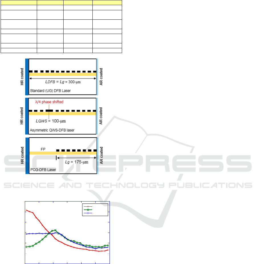
Table 2: Overview of various DFB laser structures for EML
design.
Parameter UG-DFB QWS-DFB PCG-DFB
Inte
g
ration - - Wave
g
uide
Facet coating HR/AR AR/AR or
HR/AR
HR/AR
Short active
re
g
ion
(
<200-
μ
m
)
Difficult Difficult Easy
Fabrication cost Mediu
m
Hi
g
h Low
Butt-joint
regrowth
No No Yes
Threshold
g
ain Mediu
m
Hi
g
h Mediu
m
Single-mode yiel
d
Low Goo
d
Goo
d
Figure 1: Schematic diagrams of standard UG-DFB (top),
asymmetric QWS-DFB (middle), and PCG-DFB (bottom).
Figure 2: Average longitudinal power distribution
comparison of different DFB laser structures.
In our preceding work, EMLs with partial
corrugated grating type DFB laser (PCG-EML) was
verified by simulation to have better single-mode
yield (SMY) and be immune to RFR than the original
UG-DFB based EML. The former UG-EML has
relatively poor resistance to RFR that can cause
output waveform distortion. On the other hand, PCG-
EMLs can produce better performance due to laser
stability and be approximately invulnerable to the
change of reflection from modulator facet (Sulikhah
et al, 2019, 2020, 2021). Noticing that if the
performance enhancement by PCG-EML can be kept
for higher data rate and the election of an optimal
grating length (around 60% of DFB laser section)
depends on the linear gain coefficient (Huang, 1996,
1998, 1999). Furthermore, an asymmetric QWS-DFB
structure with HR-AR coatings was demonstrated to
have a better tolerance againts optical feedback as
well as good mode selectivity compared to the
conventional symmetric QWS-DFB with AR-AR
coatings even though the fabrication process is more
complicated for a phase-shifted by e-beam writing
scemes (Zheng, 2014; Utaka, 1986).
In this research, we focused to design and analyze
the comparison of EMLs with UG-DFB, asymmetric
QWS-DFB, and PCG-DFB which can extend their
applications to a flatten intensity modulation (IM)
responses and the higher performance systems. A
new approach is proposed by optimizing grating
section parameters for 56-Gb/s EML. Both static- and
dynamic performances are evaluated with
VPIcomponentMaker Photonics Circuits tool, which
is very mature scientific and technological direction
for end-to end photonics design (e.g., cost-optimized
equipment configuration). This time-dependent
transmission line laser model (TLLM) allows an
efficient simulation of the full dynamics of multi-
section semiconductor devices with different grating
types and waveguide parameters, including their
spectral dynamic (VPIsystem Inc., 2019). It also
accounts for the forward and backward propagating
waves inside the laser as well as for the spatial hole
burning effect from non-uniform carrier and light
distribution inside the laser cavity (Lowery, 1989).
2 DEVICE MODELING
Figure 3 shows the schematic diagram of EML with
standard UG-DFB (top), asymmetric QWS-DFB
(middle), and PCG-DFB (bottom), where the DFB
section and EAM section lengths is 300-μm and 100-
μm, respectively. For asymmetric QWS-EML, its
laser section having a λ/4 phase shifted at 1/3 of DFB
laser length (L
QWS = 100-μm), while PCG type DFB
consists of an uncorrugated waveguide near the HR
rear facet and a corrugated grating (L
g = 175-μm) near
the EAM facet. The values of the key laser parameters
used in evaluating static- and dynamic performances
of EMLs are summarized in Table 3. The laser gain
0
10
20
30
40
50
60
0 50 100 150 200 250 300
UG-DFB
QWS-DFB
PCG-DFB
Average power (mW)
Distance along laser (μm)
Comparison of Different Grating Structure DFB Lasers for High-speed Electro-absorption Modulated Lasers
173
material involves a typical MQW structure operating
at 1310-nm wavelength. The DFB laser is biased with
a DC current of 70-mA. To investigate the impacts of
RFR, the modulator is modulated by 56-Gb/s PRBS-
NRZ pattern with 0.5 V voltage swing and a reverse
bias voltage of -1 V. The peak absorption wavelength
is set as 1281-nm.
Figure 3: The cross-sectional schematic diagram of EML
with standard UG-DFB (top), asymmetric QWS-DFB
(middle), and PCG-DFB (bottom).
Table 3: List of device parameters for EML with various
DFB laser structures.
Parameter Value
DFB section length 300 µm
Active region width 1.8 µm
Active region depth of MQW 0.03 µ
m
Confinement factor of MQW 0.075
Grating coupling strength 5000 m
-1
Gain compression facto
r
2.5x10
-23
m
3
Internal loss 25 cm
-1
Group index 3.73
Injection efficiency 0.75
Transparent carrier density 1.5x10
24
m
-3
Linewidth enhancement facto
r
3
Gain Model of EAM
Shape Lorentzian
EAM length 100 µm
Peak absorption 1.1x10
5
m
-1
Peak absorption linea
r
5.4x10
5
1/V
m
Peak absorption quadratic 1.51x10
6
1/V
2
m
Peak absorption cubic 4.4x10
5
1/V
3
m
Peak absorption frequency 234.025 THz
Peak absorption frequency linea
r
2.12 THz
Absorption bandwidth 3.82 THz
Absorption bandwidth linea
r
-2.56 THz/V
Saturation carrier density 5x10
24
m
-3
Figure 4 depicts the light-current (L-I) curve of
EML with three different DFB structures, where a
threshold current of ≥12-mA is exhibited. The
comparison value of static extinction ratio (SER) of
the modelled EAM has been presented in Figure 5
with SER of >5.52-dB, which has a good fit with the
experimental data (dashed line). The results offer
similar static characteristics for all various DFB lasers
and only slightly different results can be observed by
UG-EML.
Figure 4: L-I curves of EMLs with various DFB laser
structures.
-30
-25
-20
-15
-10
-5
0
-2 -1.5 -1 -0.5 0
UG-EML
QWS-EML
PCG-EML
Measured
Normalized transmission (dB)
Bias voltage (V)
Figure 5: Static extinction ratios comparison of EMLs with
various DFB laser structures with rear facet = 0°. Dashed
line is measured curve of typical EML.
3 DETAILED DEVICE
PERFORMANCES
The effects of linear gain coefficient on static SMY
and on average side-mode suppression ratio (SMSR)
for EMLs with various DFB laser structures under
rear facet phase variation from 0 to 2π are shown in
0
5
10
15
20
0 1020304050607080
UG-EML
QWS-EML
PCG-EML
Power (mW)
DC current (mA)
PHOTOPTICS 2022 - 10th International Conference on Photonics, Optics and Laser Technology
174
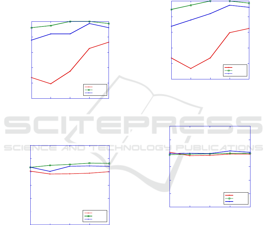
Figure 6 and Figure 7, accordingly. In general,
asymmetric QWS-EML could provide better static
SMY (>91.89%) and average static SMSR (>43.34-
dB) than PCG-EML with different linear gain
coefficients. In contrast, UG-EML shows a clear
difference that these two DFB types, whereas only
achieve <72.97% SMY with average static SMSR of
<40.5-dB. Noting that the SMY is defined as the
percentage of phase that the laser can have >35-dB
SMSR, set that the phase variation is uniformly
distributed between 0 and 2π.
0
0.2
0.4
0.6
0.8
1
678910
UG-EML
QWS-EML
PCG-EML
Static SMY
Linear gain coefficient (x10
-20
m
2
)
Figure 6: Effect of linear gain coefficient on static single-
mode yield for EMLs with various DFB laser structures
under 10
-3
RFR.
0
10
20
30
40
50
60
678910
UG-EML
QWS-EML
PCG-EML
Average static SMSR (dB)
Linear gain coefficient (x10
-20
m
2
)
Figure 7: Effect of linear gain coefficient on average static
SMSR for EMLs with various DFB laser structures under
10
-3
RFR.
Then, we compare the simulated dynamic SMY
(Figure 8) and average dynamic SMSR (Figure 9)
under 56-Gb/s NRZ signal with different linear gain
coefficients. From the simulations, UG-EML is
sensitive to the change in facet phases, which is
persistent with the previous findings of worse
resistance to external reflection for UG-DFBs (Grillot
and Thedrez, 2006). Moreover, both asymmetric
QWS-EML and PCG-EML can have for about the
same average dynamic SMSR (~39.8-dB), but
asymmetric QWS-EML could obtain a higher
dynamic SMY (89.19%) compared to PCG-EML,
where the SMY are gradually increased for larger
linear gain coefficient.
0
0.2
0.4
0.6
0.8
1
678910
UG-EML
QWS-EML
PCG-EML
Dynamic SMY
Linear gain coefficient (x10
-20
m
2
)
Figure 8: Effect of linear gain coefficient on dynamic
single-mode yield for EMLs with various DFB laser
structures under 10
-3
RFR.
0
10
20
30
40
50
60
678910
UG-EML
QWS-EML
PCG-EML
Average dynamic SMSR (dB)
Linear gain coefficient (x10
-20
m
2
)
Figure 9: Effect of linear gain coefficient on average
dynamic SMSR for EMLs with various DFB laser
structures under 10
-3
RFR.
The simulated eye diagrams under 56-Gb/s NRZ
signal for EMLs with various DFB laser structures is
shown in Figure 10 with linear gain coefficient of
6x10
-20
m
2
, rear facet of 290°, and 10
-3
reflectivity.
The Q-value of UG-EML, asymmetric QWS-EML,
and PCG-EML is 5.45, 10.12, and 15.06,
respectively. That is, the relative phase between rear
facet and gratings incredibly affect the output
waveform since it is susceptible to the optical
Comparison of Different Grating Structure DFB Lasers for High-speed Electro-absorption Modulated Lasers
175
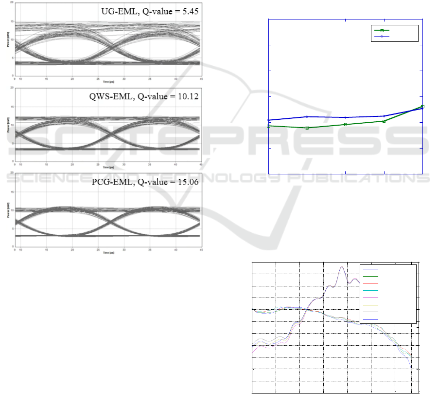
feedback induced fluctuation in field distributions.
Hence, the improved immunity to RFR for PCG-
EML results from the insensitivity to the HR facets
thus better eye diagrams against the EML with
asymmetric QWS-DFB and UG-DFB. The detailed
comparison of simulated average quality factor for
both PCG-EML and asymmetric QWS-EML with
different linear gain coefficients under 10
-3
reflectivity is shown in Figure 11, which is extracted
from eye diagrams under 56-Gb/s NRZ signal. PCG-
EML could produce a slightly better average Q-value
(>20.8), which is about the same performance with
the asymmetric QWS-EML when linear gain
coefficient = 10x10
-20
m
2
.
Figure 10: Eye diagrams at 56-Gb/s NRZ signal UG-EML
(top), asymmetric QWS-EML (middle), and PCG-EML
(bottom) with rear facet = 290°.
Figure 12 depicts the S21 measurement of typical
PCG-EML with various bias voltages, which
discloses no big difference between PCG-EML, UG-
EML, and asymmetric QWS-EML. The 3-dB
bandwidth of the EML can be >40-GHz, whereas the
transitions of the relaxation oscillation from the peak
to dip (i.e., low-frequency drop (LFD)) can be seen in
the IM response of EMLs occurred at about 5-GHz.
Furthermore, we investigate the simulated intensity
modulation responses for three different structures of
UG-EML, asymmetric QWS-EML, and PCG-EML
with rear facet of 30°. The LFD analyses for different
bias voltages are summarized in Table 4. As depicted
in Figure 13, both PCG-EML and asymmetric QWS-
EML can have a comparable LFD results, whereas
QWS-EML produces a better result for some
operating bias voltages, especially under 10
-3
RFR.
On the other hand, UG-EML provides more negative
LFD, which means more influenced by RFR,
compared the two other lasers. Based on these results,
both PCG-DFB and asymmetric QWS structures
implement a potential candidate in designing high-
speed transceivers with robust reliability against the
conventional EML with uniform grating. The
integrated views of the next requirements of
datacentre call for the new architectures based on
optical interconnects.
0
10
20
30
40
50
60
678910
QWS-EML
PCG-EML
Average Q-value
Linear gain coefficient (x10
-20
m
2
)
Figure 11: Comparison of simulated average quality factor
between PCG-EML and asymmetric QWS-EML with
different linear gain coefficients at 56-Gb/s NRZ signal
under 10
-3
RFR.
Figure 12: S21 and S11 of typical EML with various bias
voltages.
0 10 20 30 40 50 60 67
-21
-18
-15
-12
-9
-6
-3
0
3
6
9
12
S21(dB)
frequency(GHz)
0 10 20 30 40 50 60 70
-20
-10
0
S11(dB)
Vea=-0.7V S21
Vea=-0.9V S21
Vea=-1.1V S21
Vea=-1.3V S21
Vea=-0.7V S11
Vea=-0.9V S11
Vea=-1.1V S11
Vea=-1.3V S11
PHOTOPTICS 2022 - 10th International Conference on Photonics, Optics and Laser Technology
176
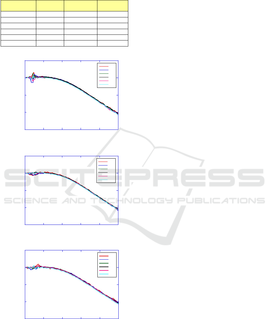
Table 4: LFD analyses for different EML structures.
Bias Voltage
(V)
UG-EML QWS-EML PCG-EML
-0.8 1.6 dB -0.8 dB -0.4 dB
-1 -2.7 dB -0.6 dB -0.8 dB
-1.2 1.4 dB -0.2 dB -0.5 dB
-1.4 -0.4 dB -0.1 dB -0.2 dB
-1.6 -1 dB -0.1 dB -0.1 dB
-1.8 -0.4 dB -0.2 dB -0.6 dB
-15
-10
-5
0
5
0 1530456075
UG-EML
-0.8
-1
-1.2
-1.4
-1.6
-1.8
Normalized frequency response (dB)
f (GHz)
Bias voltage (V)
-15
-10
-5
0
5
0 1530456075
QWS-EML
-0.8
-1
-1.2
-1.4
-1.6
-1.8
Normalized frequency response (dB)
f (GHz)
Bias voltage (V)
-15
-10
-5
0
5
0 1530456075
PCG-EML
-0.8
-1
-1.2
-1.4
-1.6
-1.8
Normalized frequency response (dB)
f (GHz)
Bias voltage (V)
Figure 13: The simulated intensity modulation responses
for UG-EML (top), asymmetric QWS-EML (middle), and
PCG-EML (bottom) with rear facet = 30°.
4 CONCLUSIONS
We have successfully demonstrated and investigated
the performance comparison of EMLs with three
different DFB laser structures. The simulation
suggests that both asymmetric quarter-wave-shifted
and partially corrugated grating based EMLs could
provide a better dynamic single-mode yield of
89.19% compared to conventional EML with uniform
grating (<64.87% dynamic SMY), but PCG-EML
produces a better average Q-value of >20.8 at 56-Gb/s
NRZ signal against the two other lasers even with
strong reflection from the front section. It also
indicates lower low-frequency drop for two types of
EMLs with asymmetric QWS-DFB and PCG-DFB
(>-0.8 dB) than the original UG-EMLs (-2.7 dB).
Therefore, PCG-DFB with HR/AR structure provides
a better choice for low-cost and high-speed EML
applications.
ACKNOWLEDGEMENTS
The authors would like to thank the Ministry of
Science and Technology (MOST), Taiwan for their
financial support for this work under the grant
number MOST 109-2622-E-011-001-CC1.
REFERENCES
Li, X., Gu, Q. (2019). High-speed on-chip light sources at
the nanoscale. Advances in Physics, 4(1), 761-769.
Spyropoulou, M. et al (2020). Towards 1.6T datacentre
interconnect technologies: The TWILIGHT
perspective. Journal of Physics Photonics, 2(4), 1-5.
Ambrosia, J.D. (2021). The case for 1.6 Terabit Ethernet.
In IEEE 802.3 Beyond 400 Gb/s Ethernet Study Group
Electronic May 2021 Session.
Ozolins, O. et al (2017). 100 GHz externally modulated
laser for optical interconnects. Journal of Lightwave
Technology, 35(6), 1174-1179.
Pukhrambam, P.D. et al (2017). Electroabsorption
modulated lasers with immunity to residual facet
reflection by using lasers with partially corrugated
gratings. IEEE Photonics Journal, 9(2), 1-17.
Hossain, M.S.B. et al (2021). 402 Gb/s PAM-8 IM/DD O-
band EML transmission. In European Conference on
Optical Communication. Bordeaux, France.
Kobayashi, W. et al (2009). 40-Gbit/s, uncooled (-15 to
80°C) operation of a 1.55-μm, InGaAlAs,
electroabsorption modulated laser for very short reach
applications. In IEEE International Conference on
Indium Phospide & Related Materials. Newport Beach,
CA, USA.
Comparison of Different Grating Structure DFB Lasers for High-speed Electro-absorption Modulated Lasers
177

Kwon, O.K. et al (2012). Electroabsorption modulated laser
with high immunity to residual facet reflection. IEEE
Journal of Quantum Electronics, 48(9), 1203-1213.
Cheng, Y. et al (2014). 1.55 μm high speed low chirp
electroabsortion modulated laser arrays based on SAG
scheme. Optics Express, 22(25), 31286-31292.
Ohata, N. et al (2020). High-speed optical devices and
packaging techniques for data centers. In SPIE OPTO.
San Francisco, CA, USA.
Abbasi, A. et al (2017). Direct and electroabsorption
modulation of a III-V-on-Silicon DFB laser at 56 Gb/s.
IEEE Journal of Selected Topics in Quantum
Electronics, 23(6), 1-7.
Ahmad, Z. et al (2019). High-speed electro-absorption
modulated laser at 1.3 µm wavelength based on
selective area growth technique. In IEEE Photonics
Conference. San Antonio, TX, USA.
Yamauchi, S. et al (2021). 224-Gb/s PAM4 uncooled
operation of lumped-electrode EA-DFB lasers with 2-
km transmission for 800GbE application. In Optical
fiber Communication Conference. San Francisco, CA,
USA.
Tsuyoshi, T. (2012). High-speed directly modulated lasers.
In The National Fiber Optic Engineers Conference. Los
Angeles, CA, USA.
Sulikhah, S. et al (2019). Enhancement of modulation
responses of directly modulated lasers with passive
feedback and partially corrugated grating. In 24
th
Microoptics Conference. Toyama, Japan.
Sulikhah, S. et al (2020). Demonstration of improved
immunity to residual facet reflection for uncooled
EMLs with partially corrugated grating. In
Optoelectronics and Communications Conference.
Taipei, Taiwan.
Sulikhah, S. et al (2021). Improvement on direct
modulation responses and stability by partially
corrugated gratings based DFB lasers with passive
feedback. IEEE Photonics Journal, 13(1), 1-15.
Huang, Y. et al (1996). External optical feedback resistant
characteristics in partially-corrugated-waveguide laser
diodes. In Optical Fiber Communication Conference.
San Jose, CA, USA.
Huang, Y. et al (1998). High-yield external optical
feedback resistant partially-corrugated-waveguide laser
diodes. In IEEE 16
th
International Semiconductor
Laser Conference. Nara, Japan.
Huang, Y. et al (1999). External optical feedback resistant
2,5-Gb/s transmission of partially corrugated
waveguide laser diodes over a −40 °C to 80 °C
temperature range. IEEE Photonics Technology Letters,
11(11), 1482-1484.
Zheng, J. et al (2014). An equivalent-asymmetric coupling
coefficient DFB laser with high output efficiency and
stable single longitudinal mode operation. IEEE
Photonics Journal, 6(6), 1-10.
Utaka, K. et al (1986). λ/4-shifted InGaAsP/InP DFB lasers.
IEEE Journal of Quantum Electronics, 22(7), 1113-
1114.
(2019). VPIcomponentMaker 10.0 Photonic Circuit User’s
Manual, VPIsystems Inc. Somerset, NJ, USA.
Lowery, A.J. (1989). New dynamic multimode model for
external cavity semiconductor lasers. IEEE Proc. J.
Optoelectronics, 136(4), 229-237.
Grillot, F, Thedrez, B.J. (2006). Facet phase effects on the
coherence collapse threshold of 1.55 μm AR/HR
distributed feedback semiconductor lasers. In SPIE
Photonics Europe. Strasbourg, France.
PHOTOPTICS 2022 - 10th International Conference on Photonics, Optics and Laser Technology
178
