
Introducing a Novel ROS-based Cooperative Autonomous Vehicles
Planning Simulation Framework, CAVPsim
R. Ghahremaninejad and S. Bilgen
Mechatronics Engineering, PhD Program, Istanbul Okan University, Turkey
Keywords: Cooperative Autonomous Vehicles, Robot Operating System (ROS), Planning Simulation, CAVPsim.
Abstract: Emerging full stack autonomous driving software packages promise rapid development on autonomous
driving deployment studies. However, considering the increasing importance of cooperation among vehicles,
the absence of the Cooperative Autonomous Vehicle (CAV) research focus in those works draws attention.
In this paper, we review some CAV simulation frameworks and introduce a novel ROS based CAV Planning
simulation framework, CAVPsim. The framework has three main components: vehicle, communication, and
computation models. We verify the integration of these three components, and we show, via a simple scenario,
that cooperation of communicating autonomous vehicles can be effectively simulated on CAVPsim.
1 INTRODUCTION
Emerging full stack autonomous driving software
packages like AUTOWARE (Kato, 2018) and
APOLLO (Xu, 2020), promise rapid development in
stand-alone operation of Autonomous Vehicles
(AVs). AUTOWARE has different versions
developed on ROS (AUTOWARE AI, AUTOWARE
PILOT) and ROS2 (AUTOWARE AUTO).
APOLLO has been developed on the CyberRT
framework. A significant issue that attracts attention
regarding all these full stack software packages is the
common lack of effective contribution of Cooperative
Autonomous Vehicles (CAVs) solutions. The aim of
the present work is to contribute to ROS framework
by introducing a set of simulation components for
CAV operation to fill the current gap between
mentioned full stack AV software frameworks and
CAV research scope.
ROS (Quigley, 2009) supports built-in 3D
visualization, flexible development environment,
access to widely used data set formats, message
passing infrastructure, ability to run on multiple
distributed machines and is a widely acceptable
framework for autonomous driving applications
which makes deployment straightforward. In ROS
one can create applications running independently
and communicating with other applications via
message passing based on TCP/IP protocol.
Providing a simulation facility using ROS tools is a
common mode of ROS usage. Using benefits of the
ability to create independent applications referred as
nodes, models can be integrated as nodes in ROS. As
a result, distributed processing can be performed in
ROS and messages can be passed between models
and other components of this simulation
environment. The mentioned set of model
components, message passing infrastructure,
visualization tools, message formats can form a
Cooperative Autonomous Vehicle Simulator in ROS.
This will provide a particularly useful tool for
researchers and developers who intend to develop
distributed cooperative decision making and planning
applications. For simplicity, hereafter, the proposed
environment will be referred as CAVPsim,
Cooperative Autonomous Vehicle Planning
simulation framework.
One may use AUTOWARE software tools and
approaches for environmental modelling, HD maps,
perception and control tools. AUTOWARE uses
Open Planner stack (Hatem, 2017) as AV global and
local planner and decision maker. The generated local
plan would then be transferred to controller modules.
AUTOWARE already has pure pursuit and Model
Predictive Controller, MPC (Snider, 2009)
implemented for lateral and longitudinal controllers.
We have decided to use the same controller tools in
CAVPsim. In the present work, we propose a set of
complementary tools to be used to develop
cooperative and distributed planner solutions which
would correspond to the CAV global planning
208
Ghahremaninejad, R. and Bilgen, S.
Introducing a Novel ROS-based Cooperative Autonomous Vehicles Planning Simulation Framework, CAVPsim.
DOI: 10.5220/0010998000003191
In Proceedings of the 8th International Conference on Vehicle Technology and Intelligent Transport Systems (VEHITS 2022), pages 208-215
ISBN: 978-989-758-573-9; ISSN: 2184-495X
Copyright
c
2022 by SCITEPRESS – Science and Technology Publications, Lda. All rights reserved

module. The opportunity to study distributed
application for cooperative and distributed decision-
making algorithms in this framework rises due to the
nature of ROS which allows developers to form a
network of machines next to supporting message
passing infrastructure, known as ROS messages.
In the following, we will review similar studies
that propose simulation frameworks for CAV
research. The studies use different implementation
environments and operating system kernels (e.g.,
works of Vieira (2009) and Pereira (2012)) or use
embedded code for real time systems (e.g., works of
Bounini (2014)). In the next section we introduce
CAVPsim model components. A verification for
model components integration will also be provided.
We then conclude with a summary of CAVPsim
features, pointing out the intended user needs that
CAVPsim aims to respond to.
Simulation environments proposed by various
authors basically target their own areas of interest in
CAV operation (Do, 2019). As an example, we can
refer to the work of Vieira (2009), which is a
simulation framework to study platooning of
integrated CAVs. Work by Pereira et. Al. (2012)
suggests a more generic simulation environment and
proposes two independent simulation modules
referred as traffic simulation and robotic simulation
to simulate cooperative agents' sensors and actuators.
However, in Pereira work a model for vehicle on-
board computation resource is not provided. In work
of Bounini (2014), the authors introduce their real
time simulator with two main constituents:
1 A simulator for vehicle dynamics and
environmental simulation and sensor
behaviours.
2 Using OPAL-RT technology as vehicle
computation resource.
This, however, is a very specific embedded
hardware and software system configuration which
makes the scope far different from ours, nevertheless
worth mentioning as a complete real time CAV
simulation setup.
2 CAVPsim FRAMEWORK
CAVPsim is constructed mainly with three main
components: communication model, computation
model and vehicle model. These models can be
launched with different sets of parameters. The
operator can use ROS environment tools like
ROSbags and RVIZ next to the set of tools in
CAVPsim to interact with datasets and raw sensors’
data. Here we continue by discussing the
implementation of the three mentioned models and
corresponding verification study results. At the end of
this section, we present simulation of a simple
cooperative decision-making algorithm in a simple
driving scenario.
2.1 Communication Model
Higuchi (2019) used a communication model with
probabilistic function using ITS-G5 DSRC
characteristic parameters in their study. This model
was used to interact with the communication protocol
layer. Distributed application development in
CAVPsim requires a communication model to
interact with the communication protocol layer to
manage job batch size and expected execution time.
Due to this similarity in application of
communication model in two works, we refer to the
approach of Higuchi to model ITS-G5 as the
communication model for our work on CAV.
Considering p = exp (−λs/γτ ), as generic model to
represent probability of delivering a message between
sender and receiver with an average of s bytes as
message size, λ representing the average number of
participating vehicles, γ representing the data transfer
rate in bytes per seconds, and an average transmission
interval of τ seconds. CAVPsim communication
model will be setup with the following values for
mentioned parameters according to ITS-G5 and
DSRC specs for a pair of cooperative vehicles in a
communication range of 300 meters: λ = 2 and γ = 6
Mb/s: data rate of ITS-G5 and τ = 100 ms:
transmission rate of ITS-G5. p, probability of
delivering an incoming message and size of
messages, s.
Our aim is to model ITS-G5 behaviour toward
incoming message which is to pass it or block it based
on the probability of delivering dictated by incoming
message size. The model would measure incoming
message size and would calculate its assigned
probability of delivery.
2.1.1 Verification of Integration
To verify our model integration, we used a dataset
that stores sent messages and delivered message
streams between two communication nodes from a
logged measurement of ITS-G5 performance
according to work of Mavromatis (2019). We can
conclude our model verification by specifically
comparing received messages stream from CAVPsim
model with the logged ones. Referring to data set
presented in Mavromatis work, we get vehicle 00 as
Introducing a Novel ROS-based Cooperative Autonomous Vehicles Planning Simulation Framework, CAVPsim
209
the one which sends messages and vehicle 01 as the
one that receives those messages, so we apply vehicle
00 messages into our CAVPsim model to simulate
ITS-G5 behaviour. We configure the ITS-G5
communication model with bandwidth of 6Mbs,
message rate of 5 Hz. We represent message process
behaviour as time delay with mean of 0.12 seconds
and standard deviation of 0.02 seconds with normal
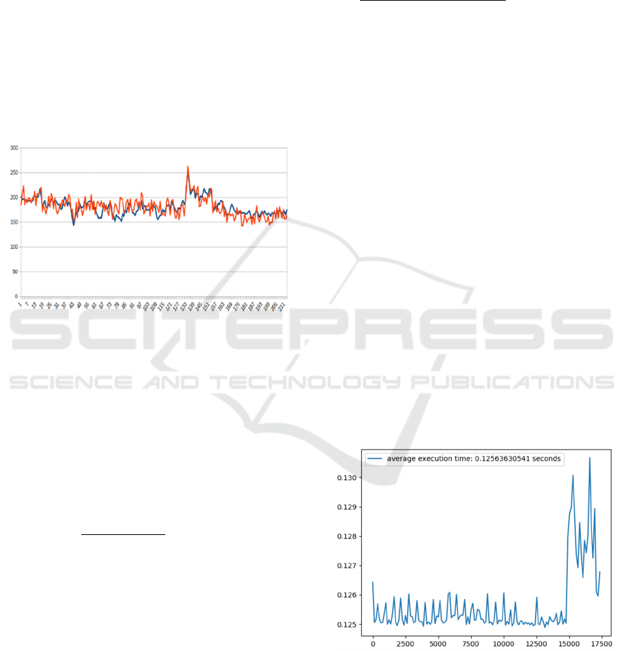
distribution. Figure (1) illustrates received messages
time stamp difference from sent ones both from
dataset and simulation results. The stochastic
behaviour of communication model would generate
slightly different time stamps at received messages
which is observable from results of multiple running
of simulation.
Figure 1: Time difference between sent and received
messages in milliseconds, per message sequence.
2.2 Computation Model
The global and the most primitive approach to
reference computation resource performance is to
measure number of floating-point operations a
machine can perform per seconds, referred as FLOPS,
FLoating-point Operations Per Second. We
characterize the computation model in CAVPsim as
inequality (1).
𝐶𝐴𝑉
(1)
Where 𝑎𝑝𝑝
is the number of floating-point
operations of each job batch of distributed processing
application, 𝑡
is the expected computation time for
job batch, 𝑏𝑎𝑡𝑐ℎ
is the size of distributed
processing job batch and 𝐶𝐴𝑉
is the available
computation resource of 𝑖
CAV in FLOPS. It is also
reasonable to expect that for the distributed algorithm
integrated in CAV on board computer, the CPU may
have run more than 𝑎𝑝𝑝
𝑏𝑎𝑡𝑐ℎ
floating
point operations since the algorithm may apply a
convergence check routine before finishing the job.
This behaviour will be modelled by 𝑎𝑝𝑝
,
application convergence coefficient where
𝑎𝑝𝑝
1 . We note that in case of
𝑎𝑝𝑝
1, we have an algorithm that does not
run an unknown number of floating-point operations
in effort to reach convergence.
𝐶𝐴𝑉
(2)
2.2.1 Verification of Integration
To verify integration of described computation
resource in CAVPsim, we initialize computation
model with following setup: 𝑎𝑝𝑝
1 ,
𝑎𝑝𝑝
10𝐾 𝐹𝐿𝑂 , 𝑏𝑎𝑡𝑐ℎ
10𝐾 and 𝑡
0.01 𝑠𝑒𝑐 and will discuss the results to verify this
model. We run a simple floating-point operation of
multiplying 3.14 by 3.14 representing 1 floating point
operation as unit and repeat it in a loop for
𝑎𝑝𝑝
𝑎𝑝𝑝
𝑏𝑎𝑡𝑐ℎ
times and measure
the execution time. Thus, we can derive the FLOPS
required from 𝐶𝐴𝑉
so we observe if inequality (1)
holds. Figures (2) and (3) show execution time and
FLOPS performed by computation model in
CAVPsim with the mentioned configuration.
The execution time of 0.125 seconds is more than
12 times higher than 𝑡
, we can conclude that we
need a smaller job batch to meet timing criteria or
need more time to perform calculation. Trading off
between job size 𝑏𝑎𝑡𝑐ℎ
and expected execution
time 𝑡
would be done by distributed application
layer. 𝑎𝑝𝑝
would be constant or a dynamic
parameter which would be evaluated in a distributed
application layer as well.
Figure 2: Execution time of computation resource model in
CAVPsim for 10K batch size and 10K FLO algorithm. The
behaviour of increasing in execution time at the final times
of simulation is due to killing data logging application of
CAVPsim which has effect on those values.
VEHITS 2022 - 8th International Conference on Vehicle Technology and Intelligent Transport Systems
210
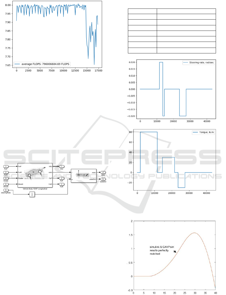
Figure 3: FLOPS in scale of 100Mega, capacity of
computation resource model in CAVPsim for 10K batch
size and 10K FLO algorithm. The behaviour of dropping
computation resource FLOPS at the final times of
simulation is due to killing data logging application of
CAVPsim which has effect on those values.
2.3 Vehicle Model
For vehicle model we refer to works of Polack (2017)
and Dong (2009) for vehicle kinematic, lateral and
one degree of freedom (1DOF) longitudinal model
integrated in Simulink. We use Simulink Coder to
generate C code out of combination of vehicle
models. Figure (4).
Figure 4: Vehicle longitudinal model and kinematic bicycle
model integration in Simulink.
2.3.1 Verification of Integration
We verify the vehicle model integration by classical
method of applying step signals as control signals for
engine torque and steering rate. We setup vehicle
model with Table (1) parameters related to TOYOTA
COROLLA 2018.
By applying same torque and steering rate
visualized in Figure (5), we verify our code
integration of vehicle model into CAVPsim. Figure
(6) shows travelled trajectory result of applying same
inputs to same model but in two different
environments, Simulink and CAVPsim. Since there is
absolutely no difference between trajectories, we
verify our vehicle lateral and longitudinal model
integration in CAVPsim referring to Simulink
integration of same models.
Table 1: Toyota Corolla 2018 parameters.
Paramete
r
Value
𝐿
2.7 meters
𝑐
0.1
𝑚
1200kg
𝑐
0.1
𝑑𝑡
Sampling time, 10 ms
𝑟
_
0.19 m
𝐺𝑅
0.09
Figure 5: Applied engine torque (N.m) and steering wheel
rate (rad/s) per milliseconds. Commands applied for 42
seconds.
Figure 6: Trajectory output of vehicle longitudinal and
lateral bicycle model in cartesian plate, meters. Simulink vs
CAVPsim.
Introducing a Novel ROS-based Cooperative Autonomous Vehicles Planning Simulation Framework, CAVPsim
211
2.4 Example Simulation Scenario in
CAVPsim
Features of CAVPsim are expected to support
simulation of CAV operation scenarios and provide a
set of tools for three components in CAV research
area, namely vehicle model, communication model
and computation model. To present a practical
example, we simulate a simple cooperative decision-
making scenario with two participating vehicles in a
common environment, sharing their trajectory created
by their local planner. CAVs are intent to compare
their own trajectory with other participants to find
possible crossings. If a crossing is detected, the time
to reach the crossing for each vehicle would be
calculated on their own computation model on which
a decision-making algorithm is integrated. The
vehicle with smaller arrival time keeps its trajectory
unchanged while the other one updates its trajectory
speed profile to prevent unsafe entry into the collision
area. They share their decision as well as their
trajectory via the communication model. We define a
circle with radius of minimum safe distance centre at
crossing point of trajectories as collision area. We
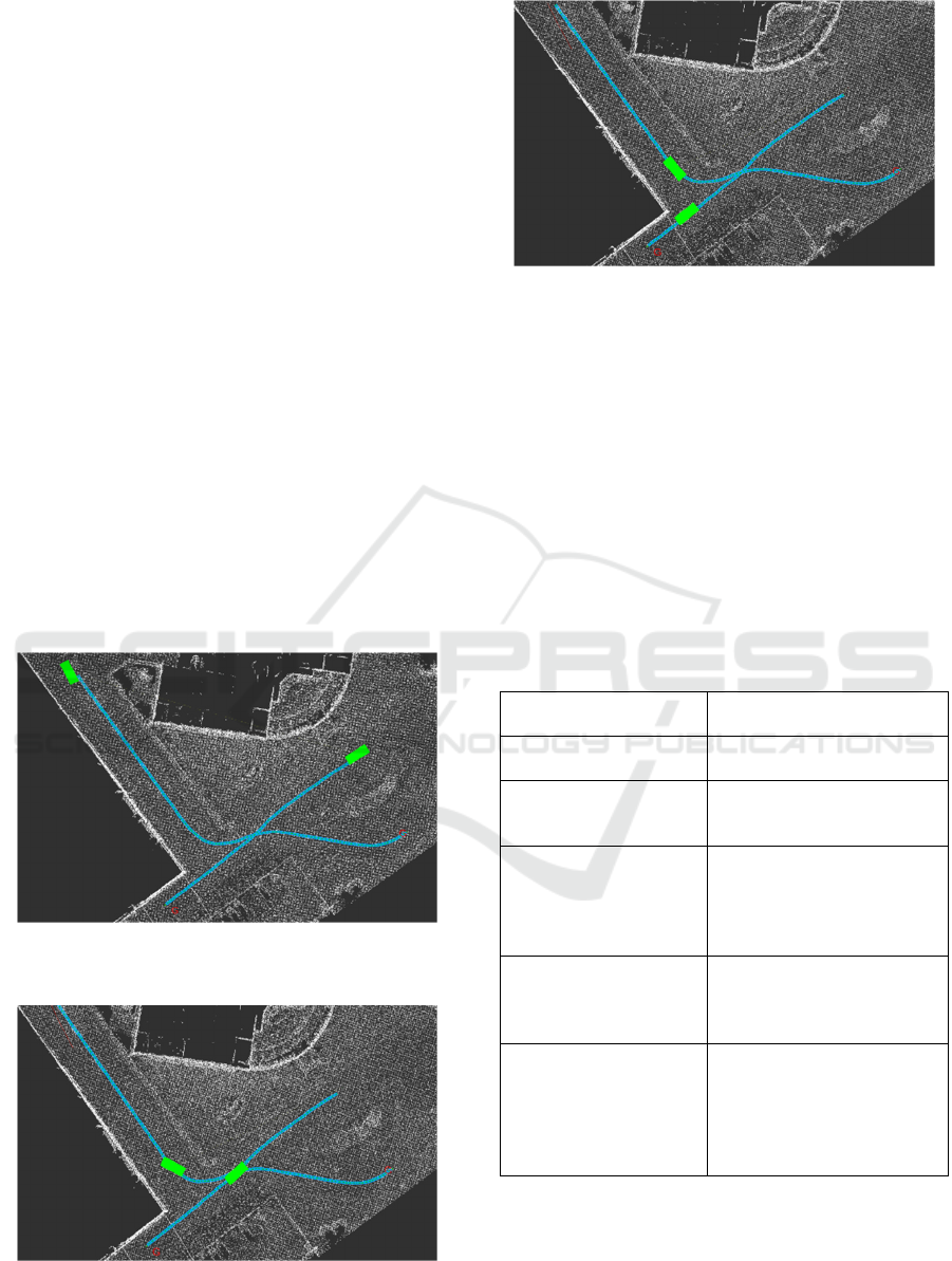
produce this scenario and present some monitoring
features of CAVPsim. We have run this simulation on
Figure 7: Initializing simulation, vehicles with their on-
board planner trajectory generation.
Figure 8: Running simulation, execution of path tracking
independently.
Figure 9: Running simulation, execution of updated speed
profile through cooperative decision-making mechanism in
CAVPsim.
CORE i7 8
th
Gen., 16Mb RAM, computer with ROS
melodic installed on Ubuntu 18.04. Figure (7) to (9)
present scenario simulation visualization on RVIZ,
ROS 3D visualization tool. Vehicles are visualized as
green cubes and trajectories are generated
independently by their on-board global planner.
We define a simple cooperative decision-making
status message to share between agents for the
purposes of this simulation, as shown in Table (2).
Table 2: Each vehicle would generate this status message
(in computation model) and share it with other participants
via the CAVPsim communication model
NAME DESCRIPTION
COLLISSION_DETECT True if crossing detected
COLLISION_DISTANC Ego vehicle to crossing point
distance in meter
COLLISION_TIME Ego vehicle time to arrive to
crossing point in seconds
considering its default speed,
5 m/s
COLLISION_SUBJECT MAC address of vehicle
which collision with
predicted.
LAST_DECISION Ego vehicle last decision to
share with the other
participant. UNKNOWN=0,
UPDATING_PATH=1,
IDLE=2
Figures (10) to (13) present some of the measuring
and monitoring results of this simulation. The
collision detected by each vehicle has resulted from
comparing ego trajectory with the other participant’s
trajectory. A 0.52 second delay between awareness of
VEHITS 2022 - 8th International Conference on Vehicle Technology and Intelligent Transport Systems
212
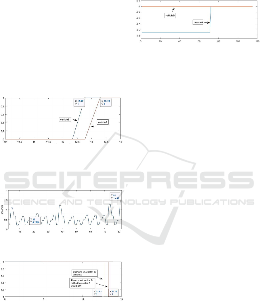
both participants of crossing trajectory is presented in
Figure (10) illustrating delay caused due to message
passing transmit rate (0.1) seconds, delay caused by
computation model for crossing point detection
search effort on trajectory points and communication
process time delay as normal distributed value with
mean of 0.1 second and deviation of 0.05 seconds.
Figure (11) shows the time difference between time
stamp of sent messages of vehicle A and time stamp
of same messages arriving on vehicle B on-board
computation. The discussed time difference for 82
sequences of vehicle A messages passed in this
simulation illustrated in Figure (11) shows stochastic
behaviour of process delay as expected.
Figure 10: Collision detection flag message per time shared
by both vehicles over the CAVPsim communication model.
0.52 seconds time difference on two message time stamps
is summation of delays caused by transmission rate,
communication process delays and computation effort
delays.
Figure 11: The time difference in seconds between 82
sequences of vehicle A transmitted messages and same
received ones on vehicle B on-board computation.
Figure 12: Change in decision per time, of vehicle A to
update its ego trajectory to avoid unsafe entry into the
collision area. Vehicle B notified of vehicle A’s decision
after 0.69 seconds. The logic of deciding who will change
its trajectory is evaluated on both vehicles’ onboard
computation models, which means vehicle B is aware that
it is not the one changing its decision.
Figure 13: Speed profile in m/s per waypoint index. Vehicle
A updates its trajectory to avoid unsafe entry to detected
collision area. It starts with lower speed than its default
value, 5 m/s until vehicle B passes the area. Vehicle B
doesn’t change its speed profile according to the decision-
making logic since vehicle B requires smaller time to pass
the area, it preserves its default speed profile.
With this very simple scenario we have illustrated
the facility to simulate message passing between
communicating vehicles in a common environment,
together with the implementation of a simple decision
maker for our scenario case. This can be extended to
more complicated decision-making tasks by
imposing set of different driving scenarios. Proposing
generic models in CAVPsim and using benefits of
ROS environment and open-source full stack self-
driving software like AUTOWARE promises rapid
development of CAV related solutions. The effort for
researchers would be to set parameters for those
models and to develop decision making and/or
planning algorithms into computation model node.
Those computation model nodes in case of
complexity can also execute on distributed machines
using benefit of ROS environment, so integration of
complex decision-making algorithms on distributed
machines would be straightforward. We also note that
the computation model developed in CAVPsim
which basically would be place for our decision-
making algorithm together with communication
messages defined during the development could port
on real vehicles with almost no changes in
implementation and code integration. The real
computation of each vehicle would run this
computation model and its message exactly the way
we run it in simulation. The last feature also reduces
HIL tests effort.
3 CONCLUSIONS
CAVPsim provides a simulation facility that consists
of three fundamental models, namely the
communication, computation and vehicle models,
which can be used together with the user’s decision-
making algorithms for observing collective behaviour
of multiple CAVs operating over a ROS environment.
Introducing a Novel ROS-based Cooperative Autonomous Vehicles Planning Simulation Framework, CAVPsim
213

To illustrate CAVPsim interaction with ROS and
Linux kernel layer we can refer to Figure (14).
Figure 14: CAVPsim on top of ROS which also uses some
general ROS tools.
Message passing is a crucial requirement to
develop a distributed algorithm. It is also clear that
the ability of swift transition from simulation
environment to deployment is a fundamental
requirement. The ability to run distributed application
on single or multiple connected machines promises
effortless transition from development and simulation
stage in CAVPsim to deployment stage, meaning, we
can simply replace the CAV models with real CAVs
running distributed application next to their onboard
processing of sensors and actuators. CAVPsim can
make use of a real data set of perception information
such as HD maps, object detection methods etc. as
well as from any ROS based software stack like
AUTOWARE. This also points to the opportunities
that CAVPsim provides for rapid prototyping projects
based on full stack AV driving software.
3D visualization of the vehicle movement in an
operation environment like HD map, plotting tools
etc. are generally mandatory for analysing variables
of interest which should be considered as simulator
features. Ability to import data for benchmark and/or
export data in a widely acceptable data structure
would also boost the benchmark study. CAVPsim
uses benefits of ROS built-in tools next to extra tools
to interact with third party resources such as RVIZ for
3D visualization, or data export and import tools
to/from MAT and CSV files from third party
resources like Matlab/Simulink.
We aim to proceed with future studies on
CAVPsim in two main directions:
- Development of CAVPsim environment by
adding different models/modelling
approaches for the three main components and
development of data visualization/monitoring
tools.
- Developing generic scenario generator
modules like crossing scenarios, round-about,
etc.
We believe improvement in both aspects would
result in great contribution to CAV researcher’s
community to get in touch with current AV driving
full stack software.
ACKNOWLEDGEMENTS
We would like to thank ADASTEC co. for their
support on proving required materials and tools to
conduct this work. Special thanks to Dr. Ali Ufuk
Peker and Dr. Kerem Par for the review of this work.
REFERENCES
Kato, S., Tokunaga, S., Maruyama, Y., Maeda, S.,
Hirabayashi, M., Kitsukawa, Y., ... & Azumi, T. (2018,
April). Autoware on board: Enabling autonomous
vehicles with embedded systems. In 2018 ACM/IEEE
9th International Conference on Cyber-Physical
Systems (ICCPS) (pp. 287-296). IEEE.
Kato, S., Takeuchi, E., Ishiguro, Y., Ninomiya, Y., Takeda,
K., & Hamada, T. (2015). An open approach to
autonomous vehicles. IEEE Micro, 35(6), 60-68.
Xu, K., Xiao, X., Miao, J., & Luo, Q. (2020). Data driven
prediction architecture for autonomous driving and its
application on apollo platform. In 2020 IEEE
Intelligent Vehicles Symposium (IV) (pp. 175-181).
IEEE.
Quigley, M., Conley, K., Gerkey, B. P., Faust, J., Foote, T.,
Leibs, J., Wheeler, R. & Ng, A. Y. (2009). ROS: an
open-source Robot Operating System. In ICRA
Workshop on Open Source Software.
Hatem, D., Eijiro, T., Kazuya, T., Yoshiki, N., Adi, S.,
Morales, L. Y., ... & Shinpei, K. (2017). Open Source
Integrated Planner for Autonomous Navigation in
Highly Dynamic Environments. Journal of Robotics
and Mechatronics, 29(4), 668-684.
Snider, J. M. (2009). Automatic steering methods for
autonomous automobile path tracking. Robotics
Institute, Pittsburgh, PA, Tech. Rep. CMU-RITR-09-08.
Do, W., Rouhani, O. M., & Miranda-Moreno, L. (2019).
Simulation-based connected and automated vehicle
models on highway sections: a literature
review. Journal of Advanced Transportation, 2019.
Vieira, B., Severino, R., Vasconcelos Filho, E., Koubaa, A.,
& Tovar, E. (2019, November). COPADRIVe-A
Realistic Simulation Framework for Cooperative
Autonomous Driving Applications. In 2019 IEEE
International Conference on Connected Vehicles and
Expo (ICCVE) (pp. 1-6). IEEE.
Pereira, J. L., & Rossetti, R. J. (2012, March). An integrated
architecture for autonomous vehicles simulation.
In Proceedings of the 27th annual ACM symposium on
applied computing (pp. 286-292).
Bounini, F., Gingras, D., Lapointe, V., & Gruyer, D. (2014,
September). Real-time simulator of collaborative
autonomous vehicles. In 2014 International Conference
on Advances in Computing, Communications and
Informatics (ICACCI) (pp. 723-729). IEEE.
Higuchi, T., Giordani, M., Zanella, A., Zorzi, M., &
Altintas, O. (2019, June). Value-anticipating v2v
communications for cooperative perception. In 2019
VEHITS 2022 - 8th International Conference on Vehicle Technology and Intelligent Transport Systems
214

IEEE Intelligent Vehicles Symposium (IV) (pp. 1947-
1952). IEEE.
Mavromatis, I., Tassi, A., & Piechocki, R. J. (2019,
September). Operating ITS-G5 DSRC over unlicensed
bands: A city-scale performance evaluation. In 2019
IEEE 30th Annual International Symposium on
Personal, Indoor and Mobile Radio Communications
(PIMRC) (pp. 1-7). IEEE.
Polack, P., Altché, F., d'Andréa-Novel, B., & de La
Fortelle, A. (2017, June). The kinematic bicycle model:
A consistent model for planning feasible trajectories for
autonomous vehicles? In 2017 IEEE intelligent
vehicles symposium (IV) (pp. 812-818). IEEE.
Dong, J., Xu, H., Zhang, R., & Zhang, H. (2009, April).
Modeling for Vehicle Power Train and Simulation for
Vehicle Performance. In 2009 International Joint
Conference on Computational Sciences and
Optimization (Vol. 1, pp. 370-372). IEEE.
Introducing a Novel ROS-based Cooperative Autonomous Vehicles Planning Simulation Framework, CAVPsim
215
