
Automation Potentials in Public Transport based on a Depot Model
Nathalie Brenner, Nicole Rossel and Eric Sax
Karlsruhe Institute of Technology (KIT), Engesserstrasse 5, 76131 Karlsruhe, Germany
Keywords:
Automated Public Transport, Automated Depot, Daily Operating Processes, Generic Model, Class Diagram,
Morphological Matrix.
Abstract:
This paper examines the automation of public transport depots and the associated opportunities. Furthermore,
the benefits for public road operations through a step-wise transferability of these depots developments is in-
troduced. To this end, we first analyse which areas of public transport are not yet suited for the unrestricted use
of fully automated vehicles, before motivating why depots are well suited for this purpose. In the following,
the operations at two different depots and the previous work done so far are presented and abstracted in a
generic model. For the description of the model, modeling methods are introduced and a graphical notation,
defined by the unified modeling language, is applied. Based on the developed model a structured analysis of
which operations may be automated and how savings might be achieved is enabled. Finally, the transferability
to the operation on duty is discussed and the need for early inclusion of this consideration is highlighted.
1 INTRODUCTION
The hype about automated driving is increasing con-
tinuously, in the field of passenger cars as well as for
commercial vehicles. According to (Altenburg et al.,
2018) automated driving will prevail slow, but never-
theless up to 70% of the vehicles will be equipped
with a high grade of automation until 2050. This
includes the city pilot, where the driver temporarily
leaves the driving task completely to the vehicle. As
already discussed in (Brenner et al., 2019), the use
of Advanced Driver Assistance Systems (ADAS) pro-
vides several advantages, which should be transferred
to the public transportation sector. Therefore it is
important to address the benefits that transportation
companies could get out of this development too.
Particularly areas of recurring processes offer the
chance for a step-wise approach to a fully automated
operation. Suitable starting points are characterized
by a lower-variance environment and derived from
infrastructural features or special use cases. Once
potential areas of application are identified, the eco-
nomic feasibility of automation has to be evaluated,
taken into consideration whether associated advan-
tages will be enhanced or weakened by further au-
tomation in other areas. In public transport, for ex-
ample these characteristics can be found in the fixed
routes, the known schedule and the infrastructural
characteristics, as outlined in the following section.
2 AUTOMATION OF
COMMERCIAL VEHICLES
AND PUBLIC TRANSPORT
Depending on the degree of automation, different lev-
els of automated driving are defined by the Society
of Automotive Engineers (SAE) (SAE, 2019), espe-
cially for cars and commercial vehicles. Level 4 of
this definition means that a driver is no longer needed
to fulfill the driving task in limited conditions. Level
5 will even replace the driver constantly.
In the commercial vehicle sector, several ad-
vanced driver assistance systems (ADAS) are already
available today. These include passive, so purely
warning, and active, therefore intervening, systems.
Passive systems are lane departure warning and turn
collision warning systems, where the former warns
the driver when the vehicle exits the current lane and
the latter warns from collisions with pedestrians or cy-
clist in the vicinity of the vehicle. Active lane keep-
ing functions, Adaptive Cruise Control (ACC) and ad-
vanced emergency breaking functions are examples of
already available active systems. These technologies
are available from suppliers (Robert Bosch GmbH,
2021) as well as in new vehicles on the market (Daim-
ler, 2021).
In case of public transport, with one focus on the
automation of trains, trams and metros, automation
levels were also defined through the Grade of Au-
216
Brenner, N., Rossel, N. and Sax, E.
Automation Potentials in Public Transport based on a Depot Model.
DOI: 10.5220/0010998200003191
In Proceedings of the 8th International Conference on Vehicle Technology and Intelligent Transport Systems (VEHITS 2022), pages 216-225
ISBN: 978-989-758-573-9; ISSN: 2184-495X
Copyright
c
2022 by SCITEPRESS – Science and Technology Publications, Lda. All rights reserved

tomation (GoA) levels (UITP, 2019). Thereby level
2, 3 and 4 include different degrees of operational au-
tomation. Compared to the SAE levels, the focus of
the GoA levels is more on the automation of the in-
frastructure, such as through feedback devices at the
tracks and corresponding external systems for gener-
ating and processing the control signals.
For a reliable operation, it is necessary to ensure
the predictability of events and situations and to en-
able a safe operation of the vehicles. This applies on
the one hand to the planned route of the own vehicle,
which is in general defined by a starting point and the
desired destination. In the special case of public trans-
port, the advantage is that the route is fixed during a
circulation and the stops are predefined. Operation
of vehicle fleets brings further advantages, as they of-
fer the opportunity to gain extensive knowledge, by
recording data and acquire experience at any time of
the day or year for a wide range of vehicles. By know-
ing the route and the conditions that occur there, cer-
tain situations can be ruled out or limited during op-
eration. This reduces the number of variants and the
system can be better adapted to typical situations.
Unfortunately, the current legal requirements, for
example in Germany, forbid the unrestricted opera-
tion of driverless vehicles on public roads (Krampitz,
2020). But starting with a driverless operation of the
automated vehicles on restricted areas such as depots
as analysed in (Brenner et al., 2021) or bus rapid tran-
sit (BRT) the first test fields are found. To further re-
duce the number of difference and unpredictable sit-
uations, closed-off areas as depots are obvious candi-
dates. Due to the repetitive processes, they’re already
today ideal starting points for automated driving se-
quences. This makes it possible to test the systems un-
der simplified conditions today and to generate large
data sets for a comprehensive evaluation and the fur-
ther development steps.
3 GENERIC MODEL OF PUBLIC
TRANSPORT DEPOT
OPERATIONS
While autonomous cars have been a hyped topic for
decades, the automation of public transport has been a
marginal issue. However, the idea of this being a side-
lined topic is considered as outdated. Quite the con-
trary, an growing number of research projects, papers
and publications are appearing (for example (Tira-
chini and Antoniou, 2020), (Drescher et al., 2021)
or (Intelligent Transport, 2021)), accompanied by an
increasing attractiveness of the research field around
automated trams. Easily explained by the amount of
positive enabler of automated commercial vehicles,
such as an higher safety and flexibility or filling in
the lack of qualified drivers (Brenner et al., 2019). In
order to profit from this hype for the automation of
public transportation depots, the current operations on
depots have to be investigated, the automation poten-
tial identified and a well-structured basis for further
analysis with regard to automation established .
On the one hand, the automation of trams involves
a lower degree of freedom while calculating auto-
mated driving movements. The lateral control is han-
dled by the rails and guidance system. On the other
hand, the ratio of employees to passengers is more
significant in case of buses. Since the economic use
case of the latter is more attractive, buses should not
be disregarded. Therefore, in the following, the oper-
ations for trams are presented first, followed by those
for buses, in order to derive a generic model of public
transportation depots.
3.1 Current Operations on a Tram
Depot
To start, we focus on the current operating tasks for
trams, exemplary introduced for the depot in Potsdam
(based on section 6), but attention is paid to a trans-
ferability for the processes on bus depots.
The most common procedure at the tram depot is
composed of sanding and, if necessary, washing of the
vehicle. The sequence consists of 9 steps (see also ta-
ble 1 and fig. 1), starting with the return of the tram
by its driver at the end of his shift. The tram is parked
at the (interim) parking lot (1) and gets picked up by a
shunter or maintenance staff to various stations (2) for
different services, such as sanding, washing, etc (3-
4). After completing all the services the maintenance
staff drives the tram to the parking hall (6) and parks
the tram for the night (8). During this time span fur-
ther services, like interior cleaning, are possible (7).
This operation sequence is completed by the start of
the next shift of the tram driver, leaving the depot (9).
1
2
3
4
5
6
7
8
9
6
Figure 1: Abstract representation based on the depot in
Potsdam, Germany.
Automation Potentials in Public Transport based on a Depot Model
217

Table 1: Overview of operation sequences on the depots for trams and buses and its responsibilities.
No. Operation Sequence responsibilty
1 Entry of tram/bus driver
2 Drive to stations for services (maintenance hall) shunter/staff
3 Refilling Resources (e.g. sanding/refuelling) shunter/staff
4 Washing shunter/staff
5 Workshop staff
6 Drive to parking hall shunter/staff
7 Interior Cleaning and further services —
8 Parking and shut down shunter/staff
9 Exit of tram/bus driver
Although the described sequence is the most com-
mon one, there are various other alternatives. One ex-
ample occurs in case of a damage report by the driver
while returning the tram to the depot, which results in
the tram driving directly into the workshop (5). The
depot of Potsdam has two different types of workshop
tracks. Some allow passage after finished workshops
and can therefore be used for minor repairs. The oth-
ers are used for major repairs, because the tram has
to be shunted in an elaborate way for returning to the
main tracks. After the completed repair, the tram ei-
ther is directly parked or also needs additional service.
3.2 Current Operations on a Bus Depot
The operating procedures at bus depots have already
been investigated several times. While (Lauth et al.,
2019) focuses on the processes for electric bus fleets,
(Brenner et al., 2019) and (Brenner et al., 2021) in-
vestigate the operations for bus fleets with combus-
tion engines. The facilities and the layout, under op-
timal conditions, such as a rectangular property, are
described in detail in (VDV et al., 2016). Based on
this, an abstract representation was sketched and used
to illustrate the operation on bus depots (see fig. 2). In
addition, the current most common steps were high-
lighted, which were also elaborated in (Lauber et al.,
1
1
2
2
3
5
6
6
7 8
4
Figure 2: Abstract representation of a bus depot based on
the recommendations of (VDV et al., 2016).
2019). Started by the return of the bus by the bus
driver (1) and the drive to various steps by a shunter or
maintenance staff (2). Different services are provided,
such as washing or in case of vehicles with combus-
tion engines also refueling (3-4). In case of damage,
the bus is driven to the workshop (5) but the service
ends with the drive to the parking lot anyway (6) and
for electric vehicles with the service ”charging” (7).
After the parking for the night (8) the bus driver picks
up the bus for the next shift (9). So despite the differ-
ences between bus and trams, the operation steps for
bus depot are also covered by table 1.
3.3 Generic Model for Depot
Operations
For transferability of the insights, a generic model
is developed. In addition to the various instances
and their interfaces, the model provides the informa-
tion to be exchanged as well. Thereby the findings
become adaptable to other depots. Thus, every de-
pot operator may place his depot as part of the over-
all, generic model and assess which aspects are suit-
able for automation and should be focused on. Fur-
thermore this placement provides the operator with a
structured overview of the information required in the
further procedure of his automation project.
As already derived in section 3.1 and 3.2 and clar-
ified by the summary in table 1 there are no major dif-
ferences for the operational depot processes for trams
and buses, they only differ in the details of the ser-
vices. Unfortunately, the two previous descriptions
do not form a solid basis for structured analyses. A
generic model, in contrast, provides the necessary
structure for further investigations of the processes.
This model should be based on the General Model
Theory according to (Stachowiak, 1973). A subject,
motivated by a certain purpose, observes the reality
and depicts it as an model. The model has the follow-
ing three characteristics:
• Depiction: A model always depicts the original.
It is never identical to the original.
VEHITS 2022 - 8th International Conference on Vehicle Technology and Intelligent Transport Systems
218
Entry
- gate_open: bool
...
+ intruder_detection(): void
...
Bus
- status_fuel: float
...
+ Create_repair_scope(): int
...
Workshop
+ repair_in_progress: bool
...
- repair(): void
...
Parking Lot
- vehicle_parking: bool
...
- washing_inside():void
...
Hall
+ no._slots: int
...
- vehicle_enters(): void
...
Maintenance Hall
- refuel_slots_full: bool
...
- fuelling(): void
...
Vehicle
+ type: string
...
- drive(): void
...
Interim Parking Lot
- no._parking_lot: int
...
- vehicle_leaves(): void
...
Charging Lot
- maxchargingpower: float
...
- charging(): void
...
Refill Resources
- fuel_in_liter: float
...
-restore_fuel():void
...
Washing
+ washing_time: int
...
- washing(): void
...
Staff
+ job: string
...
- eating(): void
...
Social Buildings
- door_open: bool
...
- lights_out():void
...
Tram
- status_sand: float
...
- update_status(): void
...
Exit
- gate_open: bool
...
- open_gate():void
...
Test Drive
- drive_in_progress: bool
...
- route(): string
...
Figure 3: Model of public transportation depot through depiction as a class diagram.
• Abbreviation: A model never contains all features
of the original.
• Pragmatism: A model is not unambiguously as-
signed to its original.
By mapping the depot to a class diagram according to
the defined unified modeling language (UML), these
three properties are fulfilled. Only relevant proper-
ties of depots will be represented as a class diagram.
Therefore, no conclusions about a specific depot are
possible.
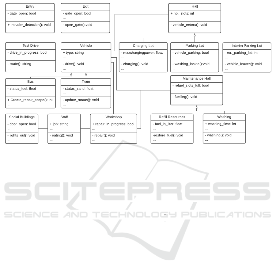
The correlations between the individual instances
are clearly apparent from the class diagram, shown
in fig. 3. Required information, communication in-
terfaces or similarities can be identified. An assess-
ment of the automatibility of each instance is possible.
For instance, the processes of tram and bus, both sub
classes to the parent vehicle, has already been de-
scribed in section 2.
Since the base class vehicle has relationships to
the other classes, the two sub classes bus and tram
share these connections too, although they may have
different characteristics. Thus the vehicle passes the
entry and exit, an electric bus would be driven to
a charging lot, while a tram would be parked at
the parking lot, both part of the parent class hall.
Also both vehicle sub classes could be driven to the
workshop by a staff. In order to provide an accurate
overview, fig. 3 not shows all inheritances, such as the
different options of power trains for buses, e.g. elec-
trified, combustion engines, hydrogen-based or hy-
brid variants. Also the class of staff could be broken
down into various child classes for more details.
By having a detailed look into the attributes
and operations a deeper understanding of the re-
quired communication interfaces is given. In case
of a needed refuelling of resources in the mainte-
nance hall, specific information about the vehicle
has to be provided. For instance the sanding level
status sand (in case of trams) or the fuel level
status fuel (in case of buses) has to be transmit-
ted by update status(). Possible implementation
options for permanent communication interfaces are
discussed in (Brenner et al., 2021) and will therefore
not outlined in detail.
However, in order to evaluate the operational pro-
cesses in their entirety and the benefits of the automa-
tion, two further forms of representations will be de-
rived.
4 DEPICTIONS OF DEPOT
OPERATIONS FOR
STRUCTURED ANALYSES
With regard to an evaluation of both the automatibility
and the associated benefits two approaches seem to
be essential. For the former concern a depiction of
the whole operation processes seems a right approach.
For the second issue individual scenarios need to be
considered. A model showing the diversity of variants
of the scenarios builds a good starting point.
Automation Potentials in Public Transport based on a Depot Model
219

4.1 Depot Operations as a Circular
Representation
For an evaluation of the operational processes in
their completeness, a representation showing the en-
tire process at the depots is suitable. Depending on
chapter 3.1 and 3.2 it is obvious, that the processes
are repeated for each vehicle every day. Therefore, a
circular representation is appropriate. By picking the
core parameters out of fig. 3 and taken the respective
operation steps into account we developed a generic
cyclic representation (see fig. 4). The respective daily
operation of each individual bus at the depot can be
summarized by the five steps: Entry, Status, Service,
Parking, and Exit.
4.2 Automatability of Depot Operations
The generic cyclic representation enables a initial ba-
sis for a well structured approach to the evaluation
of the automatability of the individual operation pro-
cesses. For this purpose, each step is examined in
more detail and options for an automation are derived.
1. Entry: There is a need of well defined handover
areas, where the driver leaves the vehicle and the
”automatic mode” is started. These handover ar-
eas have to be unambiguously marked and if nec-
essary cordoned off by automated gates or re-
tractable bollards (for higher safety against pos-
sible intruders).
Due to the missing of the driver the authorization
of the vehicle needs to be checked automatically
Entry
• Identification
• Handover areas
Status
• Pedictive
Maintenance
• Anomaly detection
Service
• Refill Resources
• Washing
Parking
• Interior Cleaning
• Charging
Exit
• Identification
• Handover areas
Figure 4: Representation of the daily operation processes
on bus and tram depots arranged with focus on the cyclic
behaviour.
(depending on placement of handover areas). Pos-
sible solution are installed easily by small adjust-
ments to the vehicle and the infrastructure. By an
installed camera either the infrastructure is able to
identify the vehicle uniquely by f.e. the plate. Or
the vehicle scans a code and registers at the entry.
In each case a match between the individual vehi-
cle and the list of admissions is necessary. (Bren-
ner et al., 2021)
After the entry the depot operating system needs
to be updated about the current position of each
vehicle (Brenner et al., 2021). While the common
way for trams is based on segments via sensors
in the track itself, various types of implementa-
tion exist in case of buses. Besides the conven-
tional localisation via GNSS, self-positioning of
the vehicle (Noda et al., 2011), WLPS (Zekavat
and Buehrer, 2012) or RFID (Ngai et al., 2007)
are also promising options. Each implementa-
tion variant offers its own advantages and disad-
vantages, resulting in a suitability depending on
the depot layout. Probably a combination of sev-
eral possibilities is appropriate to exploit advan-
tages and balance disadvantages. For instance, the
GNSS inside the parking lot could be supported
by low-cost RFID chips.
2. Status: Irrespective of the absence of a driver, the
depot operator needs to get informed about the
status of the vehicle. Previously the driver noti-
fied about the state of charge (SoC), fuel level, the
need of the vehicle to get washed, minor or major
damage and so on. With self-driving buses this
status has to be updated either by the driver at the
end of his shift or by itself. A promising method is
component monitoring or predictive maintenance.
Both can be realised via AI-based anomaly de-
tection (Chalapathy and Chawla, 2019). To rec-
ognize the damage to seats or lost items as an
anomaly and thus report a need of action could
be conceivable. It is necessary to determine which
information has to be available for a smooth work-
flow. Therefore the data can be stored in a status
vector or database and queried by the depot oper-
ator or management system.
3. Service: Depending on the queried status, the
planning and execution of the respective services
follows, what often consists of several subpro-
cesses. The most common service includes the
drive to the maintenance hall, the refuelling of re-
sources, the exterior cleaning and finally the drive
to final parking position for the night.
For executing of all those subservices driving a
predefined route and highly accurate stopping at
each service station is required. (Mercedes-Benz,
VEHITS 2022 - 8th International Conference on Vehicle Technology and Intelligent Transport Systems
220
Entry
Status
Parking
Exit
Entry Control
Status Vector
Parking Lot (Internal combustion bus)
Exit Control
Minor Damage
Parking lot (Charging for Electrical Buses)
Defect
Workshop (Major Repair)
Interim Parking Lot
Test Drive
Major Damage
Refuelling H2
Servicestation
Maintenance Hall
Workhop (Minor Repair)
Figure 5: Morphological matrix of the generalized Model of the daily operation processes on bus and tram depots.
2014) in 2014 and (Verkehrswesen, 2016) in 2016
have shown that technology is already capable of
the fulfilment of those requirements. In both cases
the vehicle drove a specified route by itself, in-
cluding stopping at specified positions.
For underlining the request of highly accurate
stopping the washing and charging process are
mentioned. In case of cleaning self-driving ve-
hicles, the ”moving part” should be realised by
the washing system. The automated vehicle, due
to the implemented and learned functionality, will
avoid the collision with an (moving) obstacle.
Therefore, for this process, the associated safety
function would have to be deactivated to avoid the
collision with the car wash component. As this
will lead to safety-critical situations, once main-
tenance staffs are present, it should be prevented
to disable safety-relevant functions. Therefore, it
is preferable that the washing procedure is carried
out for a stationary vehicle, which is parked at an
predefined position (Verkehrswesen, 2016).
But also in case of electric buses an impaired ac-
curacy of the stop position while charging could
influence the efficiency. (Walzel et al., 2016) an
future work deal with different concepts for auto-
mated charging and their challenges including the
required accuracy and the difficulty of shifting.
4. Parking for the night: The parking time during the
night offers the perfect period for charging elec-
tric buses. Depending on operating strategies and
the infrastructure, different charging methods are
possible. In addition to common plug-in charging,
there are also the possibilities of inductive and
conductive charging methods. They differ mainly
in their charging power, their power loss, bus also
in the feasibility of automation and the costs of the
implementation. These different charging meth-
ods have already been described in depth for ex-
ample in the mentioned literature (Walzel et al.,
2016) and will therefore not be considered in de-
tail. The resulting strategies are described in more
detail in (Randhahn and Knote, 2020). Conduc-
tive charging offers the advantage of charging at
terminal stop, while inductive charging even of-
fers the possibilities of charging at every stop.
A challenge for inductive charging were the in-
creasing losses with displacement of the two coils
involved in relation to each other. Bus as men-
tioned before, self-driving vehicles enables a high
degree of accuracy while stopping. Nevertheless
the adaption to the infrastructure for this charging
strategy (at every stop) entails the highest cost.
5. Exit control: Similar to the entry, the driver
takes the control within the defined handover area,
where the automated mode of the vehicle is turned
off. But in contrast to the entry control at the be-
ginning, now the correct takeover by the proper
and assigned driver has to be checked before leav-
ing the depot.
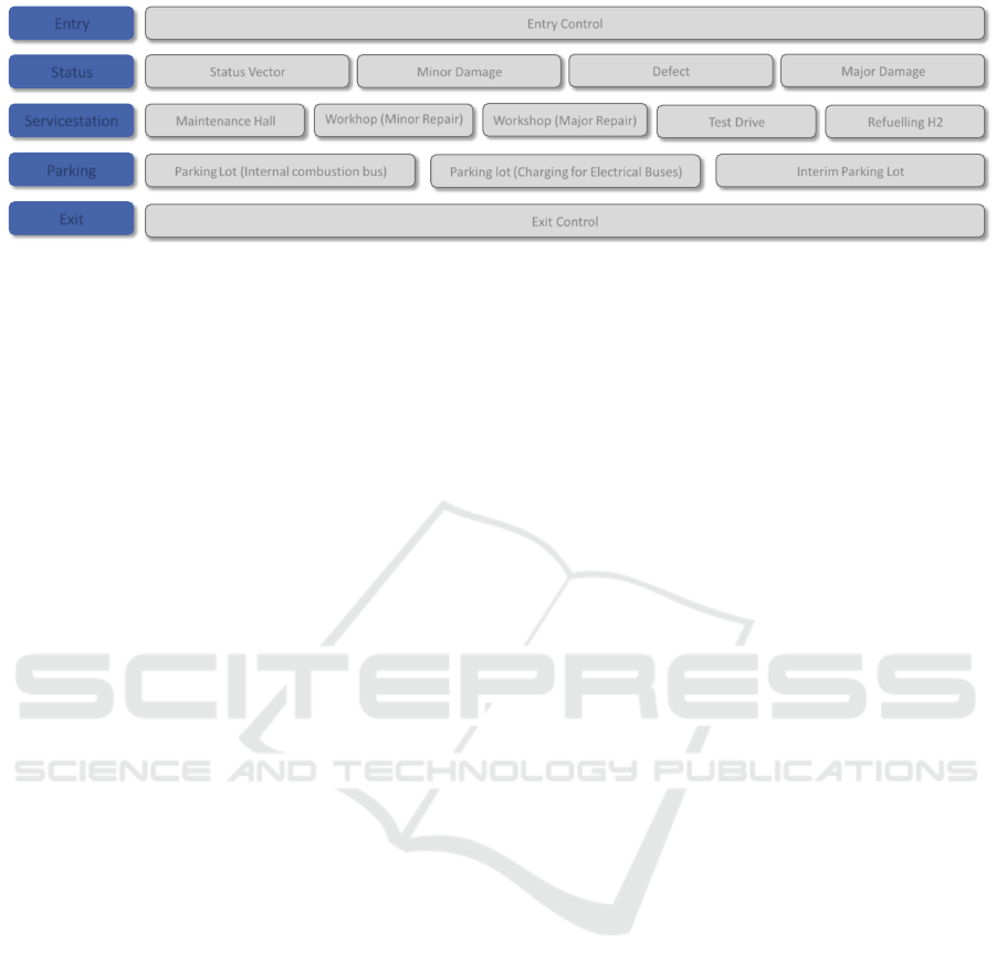
4.3 Depot Operations as a
Morphological Matrix
Setting the focus on specific, individual processes, the
generic cyclic representation is not suitable. For the
envisaged evaluation with regard to an automation of
whole scenarios, composed of several processes, a
representation as a morphological matrix is appropri-
ate. (G
¨
ohlich et al., 2018) has already shown, the mor-
phological analysis is suitable for public transporta-
tion issues, by using it for the design of an electrical
depot. In the following the methodology is adapted
to the variety of depot process sequences. The mor-
phological matrix provides a structured visualization
for further analysis. In our case we derived the five
functions with one to five options. For example, entry
and exit only provide a single choice (see also fig. 4).
But during the function ”status” a distinction between
four options is possible. While the status vector con-
tains constant as well as dynamic vehicle values, such
as the fuel/battery level or the cleaning state, a distinc-
tion has be made between individual cases of damage.
The categorization is based on ”roadworthiness” and
”road safety” (see table 2). If a vehicle is defined as
Automation Potentials in Public Transport based on a Depot Model
221

Table 2: Categorization of the three damage options accord-
ing to roadworthiness and safety.
Damage road-
Category/Option worthiness safety
Minor damage
Defect x
Major damage x x
still safe but not roadworthy, it may still complete the
route or return to the depot on its own without a tow-
ing service. In the case of minor damage, the vehicle
is withdrawn from operation on duty at an appropri-
ate opportunity, but it may still be scheduled for ser-
vice. The individual options for each functions are
illustrated in fig. 5.
In the following for each function there must be at
least one option selected, but a combination between
the individual option is possible too. Without any re-
strictions this would lead to
n
sequences
= 1 · 4! · 5! · 3! · 1 = 17.280 (1)
possible scenarios. For not analyzing this amount of
possible sequences, restriction have to be defined. An
excerpt of those restriction is:
1. If a vehicle has a defect, option minor damage is
not of interest
2. If a vehicle has a major damage, options defect
and minor damage are not of interest
3. A major damage has to be repaired at the Work-
shop (major repair).
After taking the restrictions into account, round about
80 different scenarios remain. For example, after re-
porting a defect, the subsequent visit to the workshop
and the journey to the parking garage (see fig. 6). Us-
ing the representation of the depot operation as a mor-
phological matrix, individual scenarios can be exam-
ined in detail with regard to their time and cost saving
potentials, any gaps on automatibility that may occur
or also their suitability with regard to a transfer to the
public road.
4.4 Elaboration of Automation Benefits
For the elaboration of the benefits we, once again,
use UML tools. The chosen scenario will be illus-
trated as a system sequence diagram (SSD). It offers
the options to show interactions between objects and
instances arranged in time sequences.
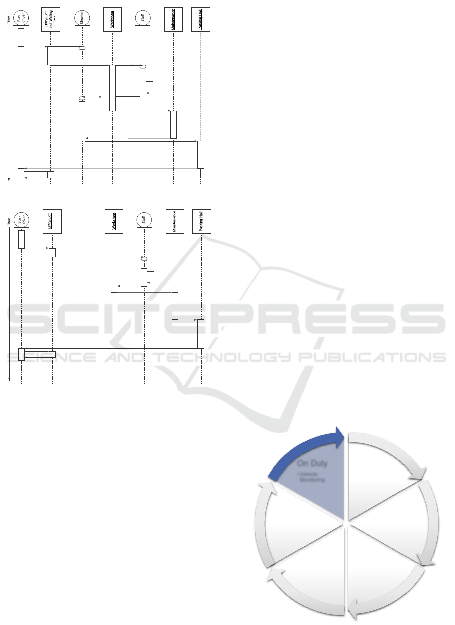
The used instances and interactions were drawn
from the class diagram (section 4.1 and fig. 3), but
provided with the mentioned time dependency. The
instances are the busdriver, a shunter, a maintenance
staff, the entry/exit, the workshop, the maintenance
hall and the parking lot. For enabling a statement of
the cost and time saving potential, fig. 7 shows the
depicted scenario with employees (shunter and staff)
as well as the automated case.
As fig. 7a shows the bus driver ends his shift by
driving through the entry and parking the bus. In
case of a defect, the occupation of the workshop has
to be planned. As soon as a time slot is available
in the workshop, a shunter is informed to catch up
the bus. But after requesting a shunter, often wait-
ing times occur until a shunter becomes available, as
they build a limited resource of the depot. After suc-
cessful handover to the workshop, the shunter is free
again and ready for the next job. The vehicle is now in
the workshop, a maintenance staff is requested, which
again results in waiting and idle time. After the vehi-
cle has been successfully repaired (which can take up
to several days) again a shunter is requested to sup-
ply the bus with resources through the maintenance
hall. Again, waiting times occur until a shunter picks
up the vehicle. The vehicle is then supplied with the
needed resources and, if necessary, gets washed. This
process takes up to 10 minutes. The shunter ends his
interaction with the vehicle by parking it in the park-
ing hall. The scenario ends with the bus driver pick-
ing up the vehicle the next day and leaving the depot
through the exit. The automated scenario (fig. 7b) pri-
marily shows the absence of the shunter. As soon as
a time slot is available the vehicle drives to the work-
shop and park at the assigned parking position on its
own. Next, a maintenance staff is requested, for ex-
ample by reporting the arrival by the vehicle to the
depot. After the repair, the vehicle will drive directly
to the maintenance hall on its own. As described in
section 4.2, a complete automated supply of the ve-
hicle would be possible, including refilling resources
and washing. The vehicle finally leaves the mainte-
nance hall and drives to its parking position for the
night. The scenario also ends with the bus driver driv-
ing out of the depot through the exit.
A comparison of the two SSDs reveals a time sav-
ing of the scenario through automation. The idle time
Entry
Status
Parking
Exit
Entry Control
Status Vector
Parking Lot (Internal combustion bus)
Exit Control
Defect
Servicestation
Maintenance Hall
Workhop (MinorRrepair)
Figure 6: Morphological matrix of the generalized Model
of the daily operation processes on bus and tram depots.
VEHITS 2022 - 8th International Conference on Vehicle Technology and Intelligent Transport Systems
222
Entry/Exit
Incl. Waiting
Time
Workshop
Maintenance
Parking Hall
Bus-
driver
Shunter
Staff
Time
(a)
Entry/Exit
Workshop
Maintenance
Parking Hall
Bus-
driver
Staff
Time
(b)
Figure 7: Sequence System Diagram of the scenario (see
fig. 6 a) with personal (shunter and staff) and b) automated
operation.
caused by the shunter is reduced to a minimum. Ob-
viously the personnel cost can be minimized by elim-
ination of the shunter. As elaborated in (Lauber et al.,
2019) the personnel costs can be reduced by at least
120.000 euros per year for depots with a fleet size of
200 buses. In addition figs. 7 show the potential time
savings, by eliminating the idle time for available em-
ployees. The workshop staff, who sometimes have to
be scheduled into the overall process due to a lack of
personnel, would have more time for repairs. This, in
turn, can lead to fewer unroadworthy vehicles. There-
fore, and due to the faster executed operational readi-
ness of each vehicle, an automated operation will lead
to a possible dispatching and provision of more vehi-
cles in the same period of time.
5 TRANSFERABILITY OF
AUTOMATION TO OPERATION
ON DUTY
Numerous challenges still need to be solved before
vehicles of SAE Level 4 or 5 can be operated in pub-
lic transport on a daily basis. Since developments in
the field of automated driving are progressing more
slowly than expected, it makes sense to define inter-
mediate developments in order to gather wide rang-
ing experience. In the field of bus automation, there
are already areas where the automation potentials an-
alyzed for depots can be transferred. Examples of this
are, on the one hand, given by existing infrastructural
characteristics such as bus stops or Bus Rapid Tran-
sit (BRT) lanes. Knowledge gained through the depot
automation can be applied, because conditions occur
there which have already been discussed.
For example, a characteristic aspect of BRT is that
the entire route, or a large part of it, is used only by
buses and therefore there is no interaction with other
road users such as cars, cyclists or pedestrians.(Volvo
Buses, 2021) Thus, the operation is characterized by
a dedicated, exclusive bus lane and therefore of an
operation with fewer variants. In addition, the auto-
mated bus must be able to approach the stops pre-
cisely so that passengers can board safely. The Fu-
ture Bus operated for several days on a BRT with-
out human intervention, including navigation through
tunnels and approaching stops with the required pre-
cision. (Verkehrswesen, 2016)
On the other hand, aspects that are covered by the
generalized concept can also be used for the develop-
ment of new functions and applications in the field of
automation in public transport. The vehicle sensors
Entry
• Identification
• Handover areas
Status
• Pedictive
Maintenance
• Anomaly
detection
Service
• Refill Resources
• Washing
Parking
• Interior Cleaning
• Charging
Exit
• Identification
• Handover areas
On Duty
• Vehicle
Monitoring
Figure 8: Extended representation based on fig. 4.
Automation Potentials in Public Transport based on a Depot Model
223

required for depot automation can be used for other
applications on duty. This makes the vehicles suitable
for the realization of systems and applications which
constitute next steps towards fully automation. Up
to now, automated vehicles have always driven alone
in solo operation. Due to the already existing sen-
sors through the automation, additional functions can
be implemented with the help of additional software.
One example of this is the Platooning of city buses.
Platooning describes the coupling of several vehi-
cles to form a unit. These vehicles follow each other
at a short distance from each other. From the point
of view of the vehicle in front, the following vehi-
cles represent a type of trailer that is not mechanically
but electronically coupled. Therefore still a driver
controls the first vehicle. The following vehicles are
driven with the help of an electronic system for auto-
matic vehicle guidance. Consequently the lead vehi-
cle sets the trajectory and all following vehicles fol-
low this this predefined path. (Kavathekar and Chen,
2012). This enables greater flexibility in public trans-
port, as the coupling and uncoupling of buses can be
used to react quickly to fluctuating numbers of pas-
sengers. Furthermore, a saving in personnel costs is
conceivable, since not every bus needs a driver any
more.
If the status vector of the vehicle is recorded by
sensors, there is a chance to use it also for the pre-
dictive analysis of the components. This means that
intelligent systems that are able to detect a fault, can
also be used during daily circulation. By networking
every bus of a fleet with the control center, the in-
formation obtained about the status of the individual
systems can be transmitted directly and do not have to
be recorded upon arrival at the depot.
Operation profiles and anomalies make it possible
to generate a comprehensive overview of the operat-
ing status of each individual bus or tram in a fleet.
In case of an error message or a conspicuous sta-
tus value of the vehicle on the track, the networking
of the vehicles can guarantee the most efficient pos-
sible procedure at the depot. This results from the
fact that if necessary repair or maintenance work is
known before the arrival of a vehicle, the operating
procedures and spare parts procurement can be opti-
mally prepared at the depot. In addition, it can be
detected whether it is a minor damage, a defect or an
major damage and the necessary procedure can be op-
timally planned. This includes, for example, a state-
ment about the operational capability of the vehicle in
its current condition. Based on this, a decision can be
made whether the day’s circulation can still be com-
pleted or that the vehicle should be taken directly to
the depot to avoid consequential damage. This leads
Status Vector Tram
Sand (fill) level
Status doors
Emergency equipment
e.g. fire extinguishers,
emergency buttons
Status lights
Status pantographs
Status stop request buttons
Status interior monitoring
systems
Status ticket validators
Status Vector City Bus
Status Batteries (For
electric buses)
Status doors
Status tyres
Status brakes
Status lights
Status ticket validators
Status stop request buttons
Fuel level (For combustion
engine buses)
Figure 9: Extract from the status vector of a tram and a bus.
to time and cost savings. For the use of electric buses,
this data exchange also supports an efficient charging
management, as the charging status of each bus can
be transmitted before it enters the depot.
To ensure safe operation, service personnel or the
driver must check a variety of conditions of the vehi-
cle. These are in particular the data shown in fig. 9 for
trams and city buses. For example, information about
the lights, the pantographs, the stop request buttons,
the ticket validators and the interior monitoring sys-
tems is important for trams in addition to those men-
tioned in the Status query section in chapter 3.3.
For the automated update process during opera-
tion the monitoring of this vehicle data can be man-
aged by using additional sensors or by evaluating ex-
isting vehicle protocols on the communication buses.
Through all the topics mentioned in this chapter,
the generalized model presented in section 4.1 can
thus be extended by an additional ”on duty” section,
as shown in fig. 8. This is intended to reflect both
the further transferability and the need for close link-
age of the specific topics. By implementing the sys-
tems for use in the field of depot automation and test-
ing them in a closed environment, the first important
findings can be obtained which are suitable for use in
daily operation in the next step.
6 CONCLUSION
Automated driving on public roads faces a countless
variety of diversity and challenges. Within this paper,
depots are investigated as suitable starting scenarios
for fully automated operation of trams and buses. A
significant amount of the processes can be automated
VEHITS 2022 - 8th International Conference on Vehicle Technology and Intelligent Transport Systems
224

by smartly integrating the state of the art and sci-
ence. Research that focuses exclusively on restricted
areas such as depots could lead into a wrong direction.
Thus, this paper addresses two key aspects to prevent
this and to make research economically viable from
the very beginning. First the automation potential and
the saving potential has to be analyzed through sci-
entific methods and subsequent analyses. In addition,
the suitability of the transfer for operation on duty has
to be considered. The insight of this paper is, that it is
crucial to consider not only a single scenario or envi-
ronment, such as the depot, but to ensure a future op-
eration on duty, enabled with the chosen solution of
automation. Furthermore, the information gathered
on duty can be used for further optimization of the
processes at the depot, using new insights. Follow-
ing this approach, a first important step towards full
automation of public transport vehicles can be made
today in order to be better prepared for future opera-
tion and to ensure a faster market introduction and a
higher acceptance and safety of the vehicles.
ACKNOWLEDGEMENTS
Part of this work has been funded by German Federal
Ministry of Transport and Digital Infrastructure in the
project AStriD (funding no. 19F2104F).
REFERENCES
Altenburg, S., Kienzler, H.-P., and Auf der Maur, A. (2018).
Einf
¨
uhrung von Automatisierungsfunktionen in der
Pkw-Flotte. Prognos AG, 58.
Brenner, N., Lauber, A., Eckert, C., and Sax, E. (2019). Au-
tonomous driving of commercial vehicles within cor-
doned off terminals. In VEHITS 2019 : proceedings
of the 5th International Conference on Vehicle Tech-
nology and Intelligent Transport Systems : Heraklion,
Crete, Greece, May 3-5, 2019. Ed.: Oleg Gusikhin,
pages 521–527. SciTePress.
Brenner, N., Lauber, A., Meier, C., Reitmeier, W., and Sax,
E. (2021). Requirements of Automated Vehicles and
Depots for the Initial Step of Automated Public Trans-
port, page 15–26. Proceedings. Springer Fachmedien
Wiesbaden.
Chalapathy, R. and Chawla, S. (2019). Deep learning
for anomaly detection: A survey. arXiv preprint
arXiv:1901.03407.
Daimler (2021). eCitaro.Safe driving.
Drescher, T., Rossel, N., and Sax, E. (2021). Bus-Platoon
im Stadtverkehr. Der Nahverkehr, page 5.
G
¨
ohlich, D., Fay, T.-A., Jefferies, D., Lauth, E., Kunith, A.,
and Zhang, X. (2018). Design of urban electric bus
systems. Design Science, 4.
Intelligent Transport (2021). RABus: the autonomous bus
trial underway in Baden-W
¨
urttemberg.
Kavathekar, P. and Chen, Y. (2012). Vehicle platooning:
A brief survey and categorization. In Proceedings of
the ASME International Design Engineering Techni-
cal Conferences and Computers and Information in
Engineering Conference - 2011, pages 829–845, New
York, NY. ASME.
Krampitz, M. (2020). Potentiale der Automatisierung im
¨
OPNV. Der Nahverkehr, page 3.
Lauber, A., Brenner, N., and Sax, E. (2019). Automated
vehicle depots as an initial step for an automated pub-
lic transportation. Poster pr
¨
asentiert auf UITP Global
Public Transport Summit (2019), Stockholm, Schwe-
den, 9.–12. Juni 2019.
Lauth, E., Mundt, P., and Gohlich, D. (2019). Simulation-
based planning of depots for electric bus fleets consid-
ering operations and charging management. In 2019
4th International Conference on Intelligent Trans-
portation Engineering (ICITE), pages 327–333. IEEE.
Mercedes-Benz (2014). Autonomous driving in the tracks
of bertha benz. In Mercedes-Benz next.
Ngai, E. W., Cheng, T. E., Au, S., and Lai, K.-h. (2007).
Mobile commerce integrated with rfid technology in a
container depot. Decision Support Systems, 43(1):62–
76.
Noda, M., Takahashi, T., Deguchi, D., Ide, I., Murase,
H., Kojima, Y., and Naito, T. (2011). Vehicle ego-
localization by matching in-vehicle camera images to
an aerial image. In Koch, R. and Huang, F., editors,
Computer Vision – ACCV 2010 Workshops, pages
163–173, Berlin, Heidelberg. Springer Berlin Heidel-
berg.
Randhahn, A. and Knote, T. (2020). Deployment of charg-
ing infrastructure for battery electric buses. In To-
wards User-Centric Transport in Europe 2, pages
169–183. Springer.
Robert Bosch GmbH (2021). On the road to realizing Vi-
sion Zero: smart sensors for commercial vehicles.
SAE (2019). Sae standards news: J3016 automated-driving
graphic update.
Stachowiak, H. (1973). Allgemeine Modelltheorie.
Springer.
Tirachini, A. and Antoniou, C. (2020). The economics of
automated public transport: Effects on operator cost,
travel time, fare and subsidy. Economics of Trans-
portation, 21:100151.
UITP (2019). World report on metro automation.
VDV, Blumenstengel, M., Herms, R., Kamender, S.,
K
¨
ahler, H., Kr
¨
amer, T., Sievers, M., and Schmitz, J.
(2016). VDV-Schrift 822 - Richtlinie f
¨
ur den Bau von
Omnibus-Betriebsh
¨
ofen.
Verkehrswesen, I. (2016). Urbane mobilit
¨
at morgen: Future
bus, urban etruck, vision van.
Volvo Buses (2021). Volvo Bus Rapid Transit.
Walzel, B., Sturm, C., Fabian, J., and Hirz, M. (2016). Au-
tomated robot-based charging system for electric ve-
hicles. In 16. Internationales Stuttgarter Symposium,
pages 937–949. Springer.
Zekavat, R. and Buehrer, R. M. (2012). Fundamentals
of Time-of-Arrival-Based Position Locations, pages
175–212.
Automation Potentials in Public Transport based on a Depot Model
225
