
Appropriate Integration of Wake-up Receivers in Simulations Tools
based on Real Experiments
Amina Whichi
1,2 a
, Robert Fromm
1 b
, Ahmed Fakhfakh
2
and Faouzi Derbel
1 c
1
Faculty of Engineering, Leipzig University of Applied Sciences (HTWK), Leipzig, Germany
2
Laboratory of Signals, Systems, Artificial Intelligence and Networks (SM@RTs),
Digital Research Center of Sfax (CRNS), Tunisia
Keywords:
Internet of Things (IoT), Wireless Sensor Network (WSN), Wake-up Receiver (WuRx), Ultra-Low Power
(ULP), OMNeT++, INET, Performance Evaluation.
Abstract:
Wireless Sensor Networks (WSNs) are an emerging and promising approach to Internet of Things (IoT).
However, energy consumption is regarded as one of the most critical problems in WSNs due to the devices’
limits.To address this problem, an ultra-low-power radio receiver known as a wake-up receiver (WuRx) is used
to handle idle listening while the main radio is turned off. Since simulators for performance prediction have
become almost indispensable in the design and management of new hardware equipment and components, we
will present in this paper the design of a wake-up receiver module, that could be a solution to the energy con-
sumption’s challenge, in OMNeT++ and compare it to experimental results, focusing on energy performance
and reliability factors.
1 INTRODUCTION
Wireless sensor networks (WSNs) have piqued the in-
terest of the scientific community in the last decade
and in the coming years, allowing us to realize
their numerous applications in disciplines such as
medicine, military, the environment, and academics.
WSNs are made up of hundreds, if not thousands, of
sensor nodes that are powered by batteries with lim-
ited energy (Cheour et al., 2013a), processing, stor-
age, and transmission capabilities. The sensor node’s
energy supply is limited, and the radio consumes a
significant amount of the node’s energy (Nithyanandh
et al., 2017) and (Shabbir et al., 2017). When there is
no communication, the ideal approach in sensor net-
works is to put the radio into sleep mode to save en-
ergy. There are two primary groups in these works:
Duty-Cycling Media Access Control(MAC) protocols
(Shabbir et al., 2017) and wake-up receivers (Sadok
et al., 2016) and (Marinkovic and Popovici, 2011).
Duty-cycling is a simple method for conserving re-
sources and extending the overall network lifespan.
For a set period of time, the node will turn off its
transceiver, only to wake up periodically to determine
a
https://orcid.org/0000-0001-5168-683X
b
https://orcid.org/0000-0002-2905-0648
c
https://orcid.org/0000-0002-7038-8157
whether or not to receive the message. The goal of
this strategy is to reduce idle listening and, as a result,
power consumption when communicating with nodes.
Different MAC protocols have also been proposed for
this approach. Most provide the basic parameter of
duty-cycle, which specifies the percentage of time a
node stays asleep and does not communicate.
Existing MAC protocols can be classified as syn-
chronous or asynchronous duty-cycling. The coordi-
nation of wake-up periods between neighboring nodes
is implied by synchronous duty-cycling. This enables
message exchange in agreed-upon time slots with no
additional interaction for each message. Coordina-
tion, on the other hand, usually implies a constant
overhead even when no messages are exchanged, also
this type of duty-cycling can present difficulty when
it comes to the synchronization. This coordination is
not used by asynchronous duty-cycling, which nego-
tiates medium access only when messages are to be
exchanged. In receiver initiated (RI) asynchronous
duty-cycling, nodes wake up from deep sleep on a
regular basis to check the radio medium. However,
in some cases this category of duty-cycling might
present a low reliability in some applications for ex-
ample the tracking and localization (Guidara et al.,
2019) , where the reference node can be unaware
about the presence of the target.
Whichi, A., Fromm, R., Fakhfakh, A. and Derbel, F.
Appropriate Integration of Wake-up Receivers in Simulations Tools based on Real Experiments.
DOI: 10.5220/0011012500003118
In Proceedings of the 11th International Conference on Sensor Networks (SENSORNETS 2022), pages 275-280
ISBN: 978-989-758-551-7; ISSN: 2184-4380
Copyright
c
2022 by SCITEPRESS – Science and Technology Publications, Lda. All rights reserved
275

To overcome these short-comes, the wake-up ra-
dios that are triggered by events propose a solution to
the problem of idle listening. Wake-up radios previ-
ously published are characterized by low-power and
low-sensitivity (Sadok et al., 2016) and (Marinkovic
and Popovici, 2011). The WuRx uses far less power
than the main transceiver and only sends an inter-
rupt when a packet with a user-defined address is re-
ceived. Embedding such a device allows for better
event-triggered applications where real-time behavior
and a longer lifetime are required. To evaluate the
new design where the WuRx is integrated for a WSN,
numerous trials with various representative scenarios
are required. Furthermore, in order to generate statis-
tically significant findings, these tests should ideally
be repeated numerous times. Performing these stud-
ies in the real world takes a lot of effort and money.
As a result,a simulator should be used to test this pro-
posed design(Halkes and Langendoen, 2014). Sim-
ulators are a low-cost and quick approach to run a
large number of experiments with various typologies
and parameter settings(Cheour et al., 2013b).In other
words, Simulators can be utilized in research exper-
iments to get more fine-grained results than similar
real-world investigations(Dwivedi et al., 2011). One
issue with simulators is that it is difficult to demon-
strate that a simulation experiment matches a similar
real-world experiment. The goal of this contribution
is to look at how well simulation findings for the wake
up receiver module and the difference between simu-
lation and real-world results will be highlighted due
to different attenuation (Ketata et al., 2020) with the
help of experimental result.
2 RELATED WORK
Studies on wake-up receivers consist mainly of two
parts: Hardware development for low-power wake-
up circuitry and software development for networking
protocols that utilize wake-up receivers. The func-
tioning principles of the wake up receiver technolo-
gies proposed in the literature or available on the mar-
ket vary. The Wake up receiver concepts can be di-
vided into two types based on their energy sources:
passive wake up receivers, in which the wake up cir-
cuitry is triggered by an external energy source, and
active wake up receivers, in which the internal battery
is used to power the wake up receiver.
2.1 Hardware Development
There are commercialized wake-up receivers that can
use an active wake-up receiver to achieve low energy
consumption. For example, there is a three-channel
wake-up receiver on the market. It features three
types of power management: sleep, standby, and re-
ceive. Many of the channels are turned off in sleep
mode. In the receive mode, the channel’s correla-
tor is working and the channel scans the input signal
waveform for a correct wake-up pattern. After an ad-
justable timeout duration, the channel returns to its
standby mode if no feedback.
The current values presented in table 1 are for all
cases where there are three channels enabled.
Table 1: The current consumption of different WuRx in the
market [3].
Operating states Regulator on Regulator off
V
CC
= 3 V V
CC
= 2.4V
Sleep current 0.8 µA 0.3 µA
Standby current 7.0 µA 6.5 µA
Receiving current 7.2 µA 6.8 µA
There are further proposals for hardware based
on the super-regenerative principle (Joehl et al.,
2001). A second lower-frequency oscillator is used by
super-generative receivers to supply a single lower-
frequency oscillator. Six orders of magnitude for sys-
tem circuit profits. This second oscillation interrupts
occasionally, the primary radio frequency (RF) oscil-
lation, which enables the steady buildup of the RF sig-
nal. Therefore, they make active wake-up receivers
that are very low-power. A prior study by Joehl et al.
(Joehl et al., 2001) presents an implementation of a
super-regenerative transceiver that consumes 3.6 mW
for a receiver sensitivity of −105 dBm, and the emit-
ter current consumption is 6 mA for 0 dBm output
power. Recently, a super-regenerative transceiver that
consumes 400 µW on reception and 1.6 mW on trans-
mission is proposed for wireless sensor networks by
(Otis et al., 2005). Also another study done by (Sadok
et al., 2016) presents a novel architecture to enhance
the WuRx sensitivity to be −60 dBm while consum-
ing 2.53 µA in channel monitoring and it is also able
to decode a 16 bit wake-up pattern.
2.2 Software Development
Although wake-up receivers offer numerous advan-
tages and are academically used in wireless sensor
networks, there are few media access control (MAC)
or routing protocols that support their use, and the
majority of available protocols are limited to simu-
lations. The current wake-up receiver protocols like
E2RMAC (Vivek et al., 2007), WUR MAC (Guidara
et al., 2019) , RTWAC [9] and GWRMAC (Karvonen
et al., 2014) support single hop contact only. Com-
pared to synchronous or asynchronous MAC proto-
EWSN-IoT 2022 - Special Session on Energy-Aware Wireless Sensor Networks for IoT
276
cols, these protocols indicate superior energy needs,
yet their efficiency is only focused on simulation data.
In (Miller and Vaidya, 2005) a loop using preamble
based synchronization between the transmitter and
the receiver is used. A triggered wake-up is often
specified, in addition to wake-up with preamble mes-
saging, in which each node wakes up once at dura-
tion T . In order to minimize the overall energy con-
sumption, the authors attempt to optimize the T val-
ues based on the given packet arrival rate. Since the
wake-up delay increases the data packets end-to-end
delay, a range of protocols are proposed to reduce
the wake-up delay experienced. One such protocol
is Latency Reduced Energy Efficient MAC (LEEM)
and it is a reservation hop. head scheme (Dhanaraj
et al., 2005). The concept is to reserve the next
hop’s channel, that is, to wake-up the next hop in ad-
vance of the destination. To support broadcasting and
dedicated messages, each node in Radio Triggered
Wake-up with Addressing Capabilities (RTWAC) has
a unique and shared wake-up address. However, the
sole purpose of wake-up messages is to initiate an
event occurrence, such as a sensor reading at the re-
ceiver node. Data communication is realized by a
more common Carrier Sense Multiple Access with
Collision Avoidance (CSMA/CA) MAC protocol that
is not further specified, using the main radio. wake-up
receivers may be used as used in (Shah and Rabaey,
2002). Since it suggests a routing protocol. The ba-
sic MAC protocol is specified for sending on a ra-
dio station, a wake-up signal. The channel access is
CSMA/CA. The use of a similar approach is in (Shah
and Rabaey, 2002), where a MAC protocol incorpo-
rating CSMA and code-division is introduced by the
authors for multiple access (CDMA). A summary of
seven separate WuRx implementations was compiled
by (Marinkovic and Popovici, 2011). Their usage was
however, not in the area of WSNs, but in the region of
networks for Wireless Body Area (WBANs).
3 SIMULATION’S
ENVIRONMENT AND RESULTS
In order to get a better understanding for the power-
hungry processes inside each sensor node and to
prove the effectiveness of the WuRx-based commu-
nication, network simulations will be run. For verify-
ing, managing, and predicting the behavior of WSNs
in a controlled and reproducible environment, net-
work simulation is used as a powerful evaluation
methodology since it is featured by the ease of imple-
mentation, low cost and scalability. for this work, the
simulation tool that chosen is OMNeT++. this sim-
ulator supports multiple radio interfaces and multiple
channels and offers an easy access to change the phys-
ical layer properties which in our case was needed to
add the new WuRx interface. for the evaluation of
the new added module, we comapred it to two duty
cycling mac protocols X-MAC and B-MAC that are
predefined in OMNeT++. in Table 2 , the different
power states values and the used parameters are pre-
sented.
Table 2: Simulation Parameter Set.
Approach Parameter Value
Carrier Frequency 868 MHz
Preamble Duration 0
Wake-Up Header Bit Length 0
Radio Antenna Type Isotropic
Bitrate 8000 bps
Modulation FSK
Protocol CsmaCa
Acknowledgements False
Receiving Power 7.5 µW
Carrier Frequency 868 MHz
Antenna Type Isotropic
Data Radio Transmitter Power 24 mW
Protocol CsmaCa
Acknowledgments True
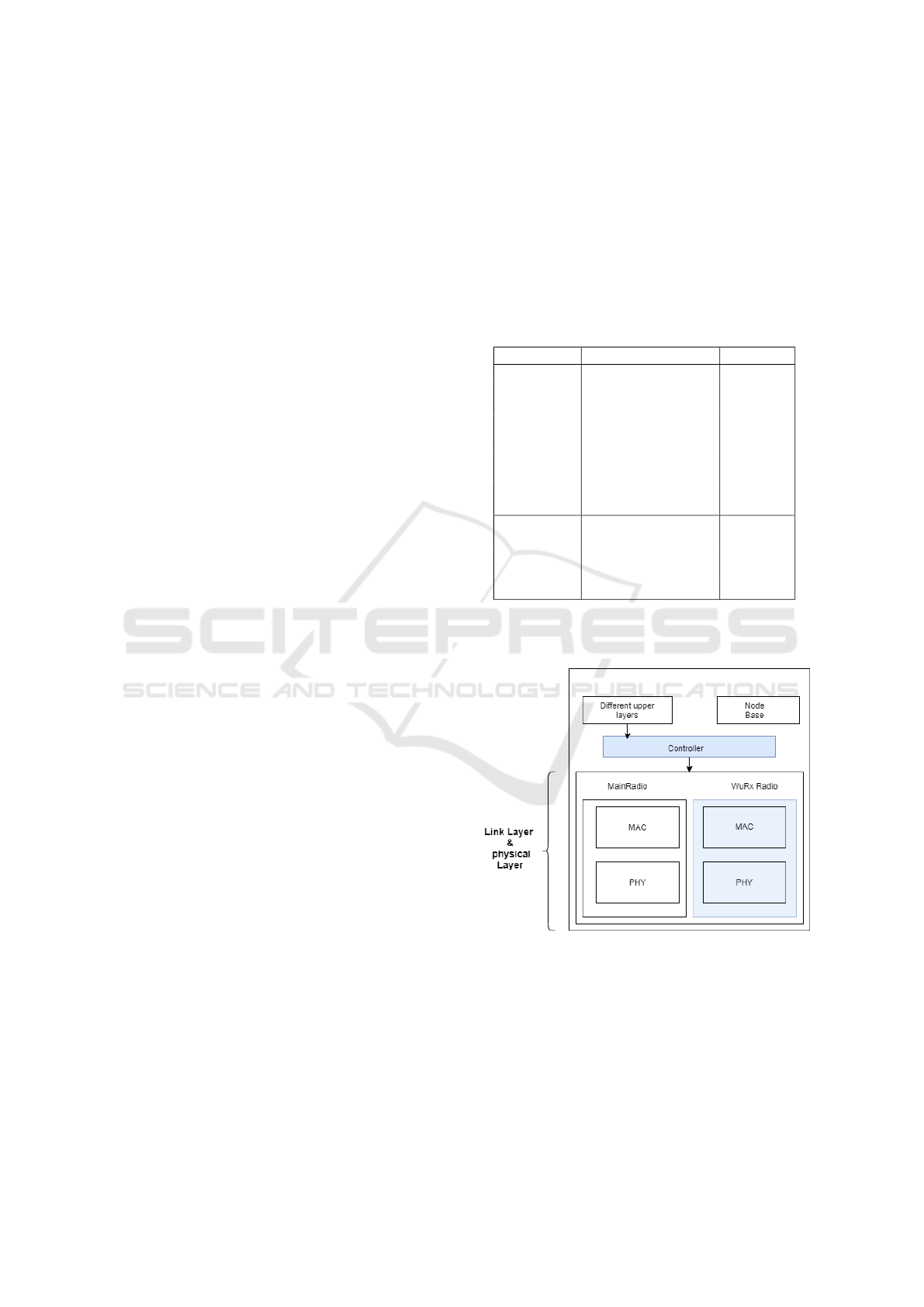
3.1 WuRx Architecture in OMNeT++
Figure 1: New proposed model of the wake-up based node
in OMNeT++.
A new model was built and implemented into the node
structure in order to investigate the WuRx behavior
in our nodes. To put it in other words, the INET
node structure was kept with the exception of modi-
fying the wireless interface by adding a second one to
include the WuRx-necessary components and a con-
troller to manage communication between the data
Appropriate Integration of Wake-up Receivers in Simulations Tools based on Real Experiments
277
link layer, physical layer (both of which are regarded
as one in this work), and network layer. Figure 1 de-
picts the node’s new planned architecture. This model
is based on the research published in (Whichi et al.,
2021) . Basically, when evaluating WuRx nodes, the
main radio is managed by a Transceiver Controller
module, depicted as Control block in 1 which allows
the application to monitor and control the status of the
transceiver as is done in WuRx platforms
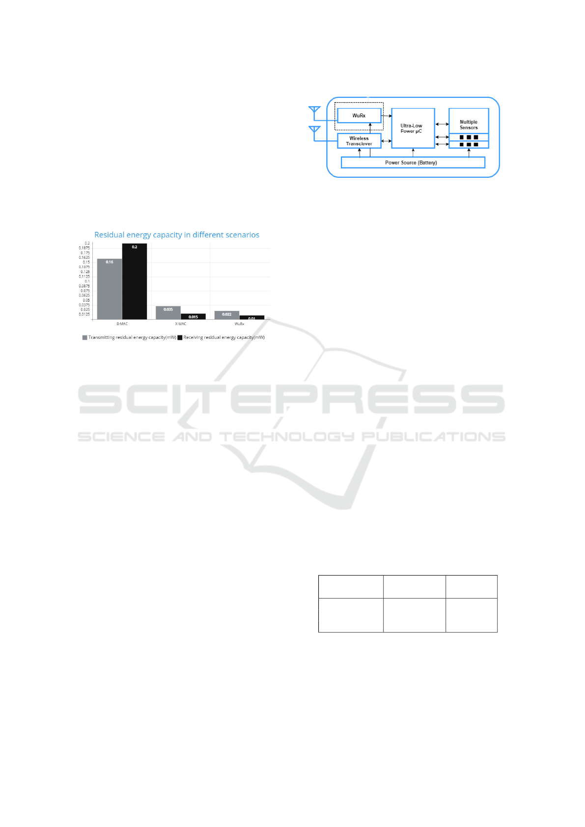
3.2 Simulation Results
Figure 2: Residual energy capacity in different scenarios.
Based on (Whichi et al., 2021), the scenario is a sim-
ple peer to peer communication where the main goal
was to compare the performance of the added mod-
ule with LPL protocols. to get a more reliable results
a physical environment was added to the network. At
the end of simulations, the WuRx module showed bet-
ter results on both aspects power consumption and re-
liability(number of received packets). compared to X-
MAc, the WuRx module consumed 37 % less power.
as in the case of the B-MAc protocol, the WuRx con-
sumed 90 % less energy. However, these results only
show the performance of the new structure with the
simulation environment and in order to evaluate the
module properly the same scenario should be con-
ducted using a WuRx hardware design. The following
section presents a set of experimental measurement
done using a BJT WuRx design done within our lab-
oratory.
4 EXPERIMENTAL
ENVIRONMENT AND RESULTS
The experimental measurements will be built up using
two sensor node ultilizing the MSP430G2553 where
one node is a transmitter and the other will just re-
ceive. The MSP430 is a series of ultra-low-power
mixed-signal microcontrollers. I also used a WuRx
implementation developed by (Fromm et al., 2021).
Figure 3: Building blocks of the WuRx-based sensor node.
The used WuRx implementation can be divided
into multiple building blocks. Figure 3 depicts the cir-
cuit’s block diagram. The antenna receives the trans-
mitted electromagnetic waves. They have a low am-
plitude, a high noise figure, and are usually affected
due interferences, reflection and diffractions. A band-
pass filter is typically used to pass only signals in the
appropriate frequency bands. However, in-band inter-
ferences between different systems operating in the
same environment are to be expected. The 868 MHz
band is employed in the proposed circuit by select-
ing an appropriate surface acoustic wave (SAW) filter.
This filter’s input and output impedances are typically
50 Ω (Fromm et al., 2021).
The experimental results were carried out inside
a laboratory.the measurements were carried using an
msp430G2553. To be able to measure the current the
following set up was set: A 1 Ω resistor was integrated
in the cable that was connected to our oscilloscope.
For the power we used a 3 V lithium battery.
4.1 Experimental Results
4.1.1 Experimental Results from WuRx
Figure 6 shows the graph of the current while receiv-
ing the wake-up packet. It is in the order of 12 µA,
based on the data sheet, which explains why the graph
is noisy.
Table 3: Comparison of currents while tranmission and
reception from datasheet, experiments and simulation for
Wupt only.
Results Transmitting Receiving
current current
Datasheet 21 mA 12 µA
Experimental 25 mA 12.57 mA
Simulation 23.1 mA 9.9 µA
In table 3 we present the comparison between
the simulation, Data sheet and experimental measure-
ments of the WuRx. These measurements intend to
evaluate the performance of the added module in OM-
NeT++. Due to the low value of the receiving current,
an amplifier was used in order to be able to detect
EWSN-IoT 2022 - Special Session on Energy-Aware Wireless Sensor Networks for IoT
278
the signal. As shown in the table, both the receiving
and transmitted current is approximately the same as
the data sheet and experimental measurements. The
difference could be explained by the Various physi-
cal environment factors, such as scattering, reflection,
or diffraction, that can influence radio transmission
in conventional wireless communication systems. In
addition to that the transmitted signal could reach
the receiving antenna through Many paths (also see
known as multi-path propagation) as a result of some
obstacles that obstruct the Line-Of-Sight (LOS) path
as well as reflections from the physical environment.
These multi path components have different terms of
time delay and amplitude attenuation and phase shift
data (Liyanage et al., 2018). Though OMNeT++ has
a physical environment module that is implemented in
the different scenarios , the difference between simu-
lation and hardware still exists since it does not con-
tain all the attenuation that could be found in reality.
4.1.2 Experimental Results for the Node
This section presents our measurements using the
same set up mentioned in the previous section but
with a10 Ω resistor.
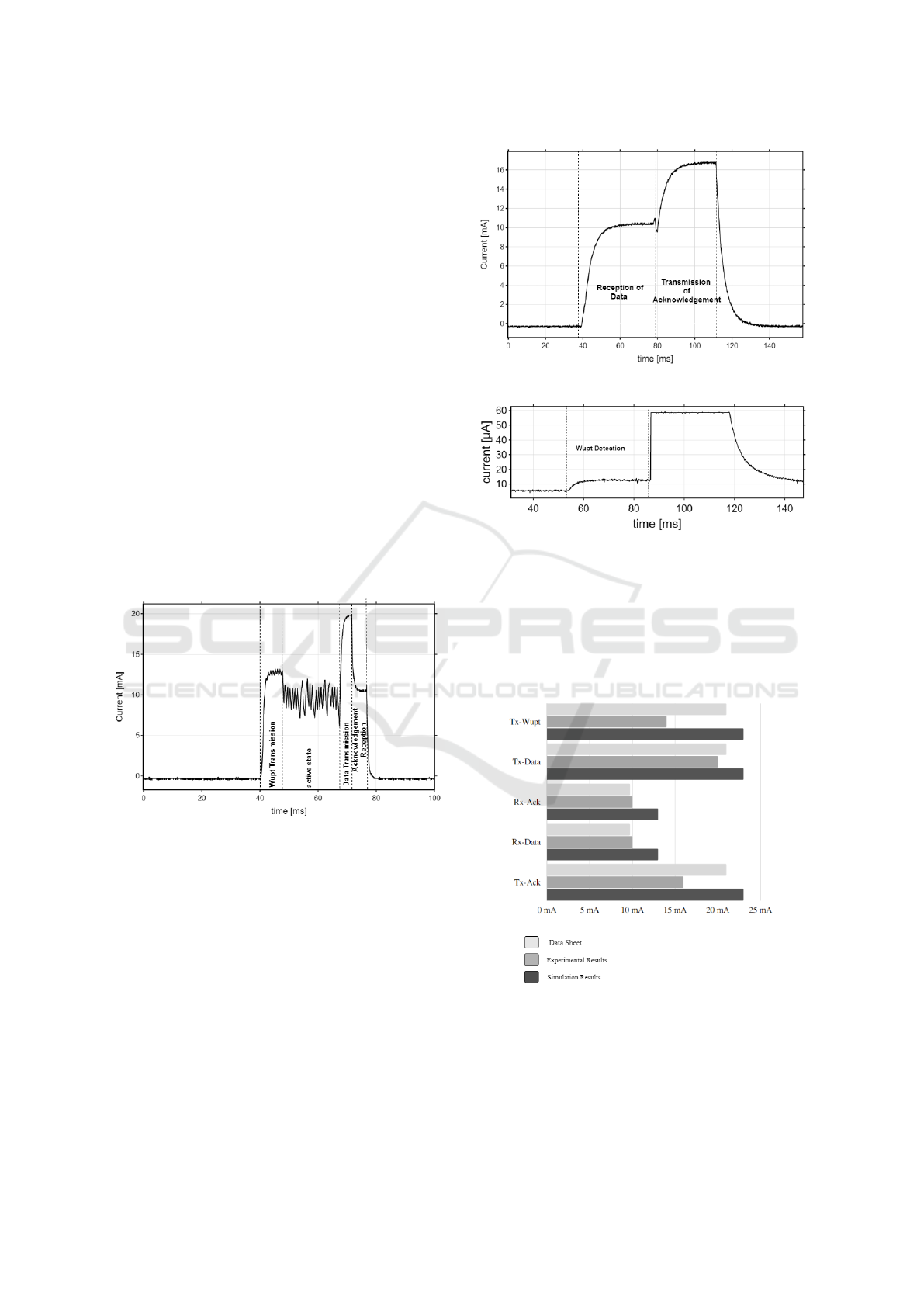
Figure 4: Current signal of the transmitter.
This figure 4 shows the current of the transmit-
ter during the 4 different states. The wake up packet
(Wupt) transmission, the active state, the Data trans-
mission state and the reception of the acknowledge-
ment. The current in the Wupt transmission is around
14 mA. This value could be explained by the fact
that during the transmission, the WuRx uses the OOK
modulation. Since the life cycle is 50 % we can
conclude that the value of the current should be (21
mA +7 mA )/2=14mA , where 21 mA is the current
while transmitting in +11 dBm and 7 mA is the cur-
rent while transmitting in -7 dBm. In the same graph
while it is amplified, a false detection of a Wupt can
be seen.
Figure 5: Current signal of the Receiver.
Figure 6: Detection of WuPt using an amplifier.
In figure 5 the signal of the Receiver and its differ-
ent states were shown.the first state is the data recep-
tion and it is of 10 mA value and the second state is
the transmission of the acknowledgement state and it
is of 17 mA. Figure 6 is the same figure but using the
amplifier in order to detect the reception of the Wupt
that is in the order of 12 µA.
Figure 7: Bar chart with the different power consumption in
different states.
The figure 7 shows the different states in all the
different environments and the power consumption.
It can be seen that even between data sheet and exper-
imental results there is a deviation due to the different
Appropriate Integration of Wake-up Receivers in Simulations Tools based on Real Experiments
279

set ups where the measurements were done and dif-
ferent conditions. Also, the performance of the added
module in the simulation has a merge of error of 9
%.This could be explained by the lack of attenuation
and interference that occurs when carrying the exper-
imental measurements.
5 CONCLUSIONS AND FUTURE
WORK
In this work, an evaluation of a WuRx model in a sim-
ulation tool is presented. In order to have a full com-
prehension of the model performance, both the simu-
lation and experimental set ups were done under the
same conditions and using the same power parame-
ters and same message length at a carrier frequency of
868 MHz. Upon comparison of the results, the simu-
lation’s WuRx model showed a small divergence from
the results shown using the MSP430G2553. This
could be explained by the fact that in general the sim-
ulations, even with introducing environment models,
are still working without taking consideration of the
material quality, other machines interference, cables’
interference. To improve the results of the simula-
tion, a new model of a CPU will be built in order to
be able to introduce different parameters of different
boards. Also new environmental modules will be im-
plemented to ensure precise results.
ACKNOWLEDGEMENTS
This research was performed at Leipzig University of
Applied Science (HTWK). The authors would like
to thank the German Academic Exchange Service
(DAAD) and the European Social Fund for the finan-
cial support and their encouragement.
REFERENCES
Cheour, R., Derbel, F., Kanoun, O., and Abid, M. (2013a).
Wireless sensor networks with power management
for low energy consumption. In Systems, Signals
I& Devices (SSD), 2013 10th International Multi-
Conference on Systems Signals and Devices Ham-
mamet Tunisia, pages 1–6. IEEE Conference Publi-
cation.
Cheour, R., Jmal, M., Lay-Ekuakille, A., Derbel, F., Ka-
noun, O., and Abid, M. (2013b). Choice of effi-
cient simulator tool for wireless sensor networks. In
Measurements and Networking Proceedings (M I&N)
2013 IEEE International Workshop on Systems, Sig-
nals and Devices, pages 210–213. IEEE Conference
Publication.
Dhanaraj, M., Manoj, B., and Murthy, C. S. R. (2005). A
New Energy Efficient Protocol for Minimizing Multi-
Hop Latency in Wireless Sensor Networks.
Dwivedi, V. K., PatleO, K., and Vyas, P. (2011). Investiga-
tion on Effectiveness of Simulation Results for Wire-
less Sensor Networks.
Fromm, R., Schott, L., and Derbel, F. (2021). An Effi-
cient Low-Power Wake-Up Receiver Architecture for
Power Saving for Transmitter and Receiver Commu-
nications.
Guidara, A., Derbel, F., Fersi, G., Bdiri, S., and Ben Je-
maa, M. (2019). Energy-Efficient On-Demand Indoor
Localization Platform based on Wireless Sensor Net-
works using Low Power Wake up Receiver.
Halkes, G. and Langendoen, K. (2014). Experimental Eval-
uation of Simulation Abstractions for Wireless Sensor
Network MAC Protocols.
Joehl, N., Dehollai, C., Favre, P., Deval, P., and Declerq,
M. (2001). A Low-Power 1-GHz Super-Regenerative
Transceiver with Time-Shared PLL Control.
Karvonen, H., Juha, P., Jari, I., Matti, H., and Carlos, P.-
R. (2014). A generic wake-up radio based MAC pro-
tocol for energy efficient short range communication.
In Personal, Indoor, and Mobile Radio Communica-
tion(PIMRC).
Ketata, I., Fakhfakh, A., and Derbel, F. (2020). Advanced
evaluation platform-based rf attenuators for wireless
sensor networks. In 2020 IEEE 6th World Forum on
Internet of Things (WF-IoT), pages 1–6. IEEE.
Liyanage, M., Chang1, C., Srirama, S., and Loke, S. (2018).
Indoor people density sensing using wi-fi and channel
state information.
Marinkovic, S. and Popovici, E. (2011). Nano-Power Wire-
less Wake-Up Receiver With Serial Peripheral Inter-
face.
Miller, M. and Vaidya, N. (2005). A MAC Protocol toRe-
duce Sensor Network Energy Consumption Using a
Wakeup Radio.
Nithyanandh, s., , and Jaiganesh, D. (2017). Wireless Sen-
sor Networks Overview and Study of Various Appli-
cations and Environmental Factors in WSNs.
Otis, B., Chee, Y. H., and Rabaey, J. (2005). A 400mW-RX
1.6mW-TX Super-Regenerative Transceiver for Wire-
less Sensor Networks.
Sadok, B., Faouzi, D., and Olfa, K. (2016). An 868 MHz
7.5 µW wake-up receiver with -60 dBm sensitivity.
Shabbir, N., , and Hassan, S. (2017). Routing Protocols for
Wireless Sensor Networks (WSNs).
Shah, R. and Rabaey, J. (2002). Energy Aware Routing for
Low Energy Ad Hoc Sensor Networks.
Vivek, J., Ratnabali, B., and Dharma, P. A. (2007). Energy-
efficient and reliable medium access in sensor net-
works. In World of Wireless, Mobile and Multimedia
Networks.
Whichi, A., Derbel, F., Fakhfakh, S., Weber, M., and Ktata,
I. (2021). Simulation of Wireless Sensor Nodes based
onWake-Up Receivers.
EWSN-IoT 2022 - Special Session on Energy-Aware Wireless Sensor Networks for IoT
280
