
From PIM and PSM with Performance Annotation to Palladio Models
Dariusz Gall
a
Wrocław University of Science and Technology, Wybrze
˙
ze Wyspia´nskiego 27, Wrocław, Poland
Keywords:
SPE, Software Performance Engineering, Performance, PCM, Palladio, MDA, Model-driven Architecture,
PIM, Platform-independent Model, PSM, Platform-specific Model, UML, Model Transformation.
Abstract:
Essential step in Software Performance Enginnering (SPE) is finding software performance characteristics. We
provide transformations of Platform Independent Model (PIM), and Platform Specific Model (PSM) models
enriched by performance annotation in Modeling and Analysis of Real-Time Embedded Systems (MARTE)
to the Palladio Component Model (PCM) performance model. The system’s structural viewpoint, i.e., PSM’s
class and deployment diagrams, are mapped to the Component Repository. The system’s behavior, i.e., se-
quence diagrams, are transformed into the PCM Service Effect Specifications. The PCM Resource Environ-
ment is generated from PSM’s deployment diagram. Finally, the PCM Usage Model is created, combining
these models and the PIM’s use cases.
1 INTRODUCTION
Software systems development tends towards au-
tomating functional requirements implementation.
It often refers to the model-driven development
approaches, including Model-Driven Architecture
(MDA) (Object Management Group, 2014). Soft-
ware development, apart from functional require-
ments, should meet various quality requirements.
One of the quality requirements is performance re-
quirements, determining, for example, the expected
system throughput, system response times, transac-
tion processing times. According to Software Per-
formance Engineering (SPE) (Smith and Williams,
2002), performance requirements, like other require-
ments, should be validated during the development
process by constructing and evaluating performance
models against the requirements. These models can
be input into the Palladio (Reussner et al., 2016), the
approach for resolving software system performance
characteristics.
We include performance requirements in software
development based on the MDA approach. In partic-
ular, we discuss how to construct the Palladio perfor-
mance models of software systems. The presentation
of the proposed approach is informal. An example
illustrates the considerations.
Papers (Hahner et al., 2021) (Reiche et al., 2021)
(Mazkatli et al., 2020) (Kroß and Krcmar, 2017) dis-
a
https://orcid.org/0000-0002-0685-1338
cuss the model-driven based construction of Palla-
dio Component Model (PCM) models. However,
they discuss generating PCM from existing imple-
mentations and only for selected software systems
types. The idea of joining model-driven develop-
ment and performance engineering is discussed in pa-
pers: (Ameller et al., 2021) (Cortellessa et al., 2007a)
(Cortellessa et al., 2007b). The authors also discuss
this topic in papers: (Walkowiak-Gall and Gall, 2015)
(Gall and Huzar, 2010) (Chudzik et al., 2011). In par-
ticular, the papers propose an MDA-based approach
incorporating performance requirements.
The paper structure is as follows. Section 2
presents the Platform Independent Model (PIM) and
the Platform Specific Models (PSM), underlining per-
formance aspects. In addition, we introduce the Palla-
dio approach and the PCM models. In Section 3, the
transformation between PIM, PSM and PCM models
are discussed, together with some illustrative exam-
ples. The paper is concluded in Section 4 by debating
the results and stating future work.
2 MDA AND PALLADIO
The MDA is a sketchily defined approach. We as-
sume that functional and performance specifications
are provided at the PIM level model and are trans-
formed into PSM implementation level models, hav-
ing made necessary architecture and design decisions,
528
Gall, D.
From PIM and PSM with Performance Annotation to Palladio Models.
DOI: 10.5220/0011090900003176
In Proceedings of the 17th International Conference on Evaluation of Novel Approaches to Software Engineering (ENASE 2022), pages 528-535
ISBN: 978-989-758-568-5; ISSN: 2184-4895
Copyright
c
2022 by SCITEPRESS – Science and Technology Publications, Lda. All rights reserved
including execution environment selection and per-
formance quality characteristics of the environment
(Walkowiak-Gall and Gall, 2015) (Gall and Huzar,
2010). Without sacrificing the generality of the paper,
we propose the following definitions of PIM models
and PSM models. Additionally, we picked Java for
the implementation platform.
2.1 Platform Independent Model
The PIM is a system specification that abstracts from
implementation details. A proposal of the PIM is pro-
vided in the paper (Walkowiak-Gall and Gall, 2015),
in the form of a UML Profile. The PIM model con-
sists of following. The information model defines the
structure of information processed within the system,
which is expressed by elements of a class diagram
(Object Management Group, 2017).
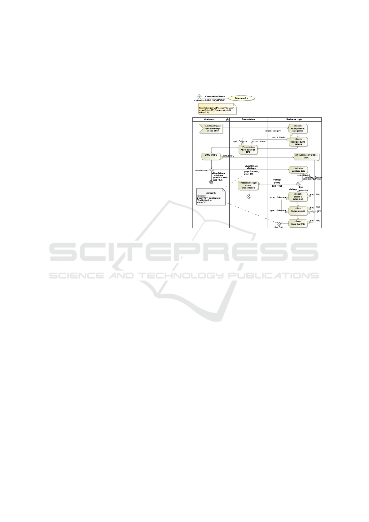
The use-case model defines use-cases and actors,
i.e., functionalities of the system and users who use
those functionalities, see Fig 1. A functionality is
specified by use-case scenarios. An activity specifies
use-case scenarios. Activity is divided into partitions,
representing participants of the behavior and group
actions for which they are responsible, Fig 1. Par-
titions used in the presented approach represent the
actor’s actions, the behavior of a system presentation
layer, and the behavior of a system logic layer.
The above PIM proposal addresses only the func-
tional aspect of PIM-level specification. Next, the
PIM-level specification of performance characteris-
tics is discussed. These characteristics are provided
using the UML language’s Modeling and Analysis of
Real-time and Embedded profile (MARTE) (Object
Management Group, 2019), supporting the modeling
of real-time and embedded systems. Performance re-
quirements are defined for a pair of an actor and a use
case. For a given actor and a use case, an intensity of
use case invocations is defined by the «gaWorkload-
Event» stereotype. Additionally, it defines an arrival
pattern of the use-case calls, either open workload -
OpenPattern or closed workload - ClosedPattern.
In addition, an annotation with probabilities is set
for each activity diagram representing a given use
case. Probabilities determine the relative frequency
of execution of a given group of scenarios. These an-
notations are attached to where the use-case scenar-
ios separate, i.e., to outgoing control nodes’ decision
flows. Such annotation is marked with the «paStep»
stereotype and a probability of transiting to annotated
control flow.
Another aspect is data exchange between an ac-
tor and a system. If characteristics of data sent or
received, e.g., data size, during actor-system interac-
tions are essential for performance analysis, it is pos-
sible to annotate such exchange with these character-
istics. Such information is stored in the message size
parameter of «paCommStep» annotation.
Figure 1: PIM example.
Last but not least is to provide expectations in
time duration execution for actor-system interactions.
They are defined by time duration constraints on these
interactions in annotations with a time expression, ex-
pressed by «paStep». Moreover, those interactions
become points of measure to verify performance char-
acteristics computed during the performance analysis
against the provided expectations.
2.1.1 Example
The Sales system is an illustrative example. Due to
space limitations, it is presented fragmentarily, one
actor and one use case representing the sales inquiry
functionality. The Fig 1 shows use-cases and associ-
ated actors. The actor Customer is associated with the
use-case SalesInquiry, i.e., it initiates this use case.
The association of actor and use-case is annotated
by the «gaWorkloadEvent» stereotype OpenPattern,
which indicates open workload intensity with general
distribution at an arrival rate of 0.1 per second.
The activity in Fig 1 is the use-case specification.
Most actions are related to system behavior, like data
fetching, data processing. These actions as a result
of transformation will turn into implementation level
calls, including implementation platform calls. These
calls will induce demands on a CPU, disks, and other
resources. The activity has performance characteris-
tics. For example, «paStep» applied to outgoing flows
From PIM and PSM with Performance Annotation to Palladio Models
529

of the decision node "decisionNode1" in an actor par-
tition states the probabilities that the actor will send
(probability=0.9) or cancel (probability=0.1) a sell
query. Similarly, «paStep» is applied to "decisionN-
ode2"’s outgoing flows in the business logic partition.
Worth mentioning is that activity within this partition
is transformed into PSM-level. Thereby, to do perfor-
mance analysis, this characteristic has to be mapped
into PSM-level as well. Finally, the model Fig 1 con-
tains the «paStep» model element spanned between
the "decisionNode1"’s output control flow "Send" and
"flowFinal." This «paStep» is an example of assert-
ing the expected time duration between two moments:
a Seller actor presses "Send," and the activity is fin-
ished. It states that the meantime of interaction dura-
tions has to be 3 seconds.
2.2 Platform Specific Models
Two models are considered at the PSM level: PSM
Specification (PSM-Spec) and PSM Instance (PSM-
Inst) (Walkowiak-Gall and Gall, 2015). The PSM-
Spec model represents the PSM-Spec architecture of
the system - it defines the types of system nodes to-
gether with the types of components arranged in them,
while the PSM-Inst model is the PSM-Inst architec-
ture, i.e., an instance of the PSM-Spec architecture.
The PSM-Spec model in UML is expressed in a
class diagram (design classes), type-level deployment
diagrams, and sequence diagrams. Design classes re-
sult from transforming an entire PIM model. The sys-
tem designer elaborates the transformation, usually
based on architectural patterns. Design classes are
arranged in nodes as reflected in the deployment dia-
gram. Sequence diagrams in the PSM-Spec model re-
sult from the transformation of activity diagrams from
the PIM model; they follow the architectural design
pattern used.
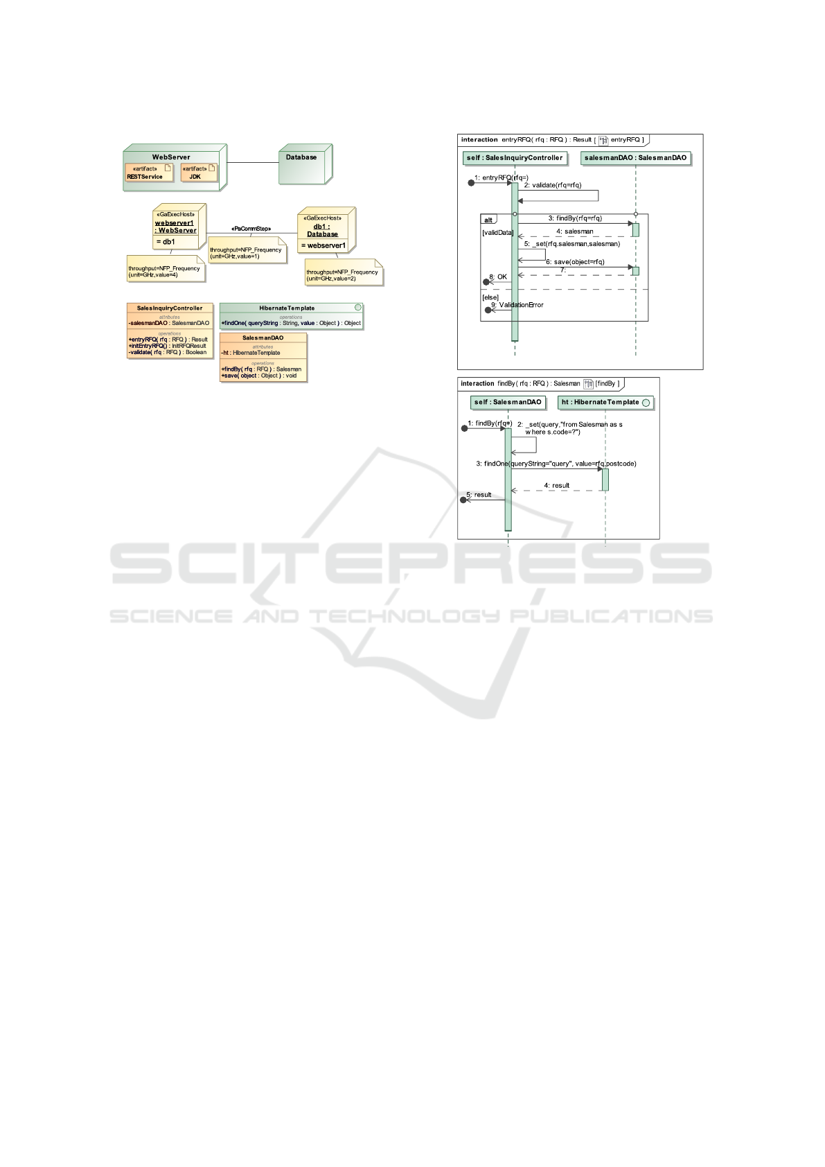
As stated before, the PSM-Spec has structural ele-
ments, which are elements present on a class diagram:
packages, classes, interfaces, see Fig. 2. They corre-
spond to Java packages, classes, interfaces. Each op-
eration always has one return parameter and can have
zero or more input parameters. There are more con-
straints, but they are omitted for the sake of brevity.
Since the PSM-Spec is at the implementation level,
it refers to elements of the implementation platform,
i.e., the Java platform. Thereby, it is necessary to
include a Platform Model (PM), i.e., a model con-
taining packages, classes, and interfaces representing
Java APIs, libraries, frameworks.
Behaviors of the PSM-Spec are defined by in-
teractions (sequence diagrams) (Object Management
Group, 2017). Each non-abstract operation has to
point to a behavior, which corresponds to the method
definition in Java. A single sequence diagram defines
this behavior according to the below constraints. The
interaction consists of a "self" lifeline representing an
object, or a class in case of a static operation, being
callee of an operation. The self lifeline defines a se-
quence of messages corresponding to a sequence of
statements in the Java method. Only interactions be-
tween the self and other lifelines are shown. See Fig
3.
There are three sets of performance characteris-
tics in the PSM-Spec. First is created by mapping
all PIM elements with performance annotation into
PSM-Spec elements, tracing a design and implemen-
tation (transformation) process.
The second is a collection of the characteristics in-
cluded in the PM model. These are stated for platform
APIs’ operations, frameworks’ behaviors and are pro-
vided by the notion of «paStep» from the MARTE
profile. The PM model’s performance characteristics
are specific to an implementation platform and para-
metrically dependent on the execution environment.
They are obtained in the process of platform perfor-
mance analysis, performance experiments (Gall and
Huzar, 2010) (Chudzik et al., 2011).
Finally, the PSM-Inst is complemented by the per-
formance characteristics of nodes and connections
between nodes. A node instance’s computational
power is defined by the stereotype «gaExecHost» and
throughput parameter. The notion of «gaCommHost»
defines a connection’s instance bandwidth, capacity,
and network latency (blocking time) parameters.
2.2.1 Example
The interactions on Fig 3 and deployment diagram,
see Fig 2, are part of a PSM-Spec model, result-
ing from the transformation of the example PIM, dis-
cussed in Section 2.1.
The interactions presents a portion of the SalesIn-
quiry use-case implementation, including invocations
of platform libraries’ operations, assigning variable
value. Both interactions are related to operations,
which are placed in design classes Fig 3. It is essential
to notice that the interaction has decision node "deci-
sionNode2", which is mapped from "decisionNode2"
of the PIM’s SalesInquiry activity in Fig 1.
Diagram in Fig 2a presents two connected nodes
with deployed artifacts. Those artifacts represent the
design classes of the PSM-Spec, see Fig 2c, in which
binary versions are situated within a given node.
The example PSM-Inst is shown in Fig 2b. It
contains a deployment diagram with nodes’ instances
and a connection instance. The nodes’ instances
are annotated by «gaExecHost» elements stating their
ENASE 2022 - 17th International Conference on Evaluation of Novel Approaches to Software Engineering
530
a)
b)
c)
Figure 2: Example of: a) Deployment specification - PSM-
Spec b) Deployment instance - PSM-Inst c) Design classes
- PSM-Spec.
performance characteristics. Similarly, the connec-
tion instance is also annotated by the notion «pa-
CommHost», providing network connection speed
characteristics. Important to mention that the exam-
ple PSM-Inst and PSM-Spec represent the system’s
instance, which can be tested for performance.
2.3 Palladio Models
The Palladio approach provides PCM, a model-
ing language for documenting software architecture
(Reussner et al., 2016) (Reussner et al., 2011). The
PCM model is an input for various tools predicting
the provided system’s quality characteristics.
The PCM describes an architecture from view-
points essential for making quality properties analysis
possible. A structural viewpoint represents the static
properties and consists of the repository and assem-
bly view types. A behavioral viewpoint specifies the
dynamics of the system. In addition, it contains qual-
ity characteristics such as information on workload
posed on the software system by actors, the speci-
fication of data provided by actors, like size, struc-
ture, and probabilities of various actors’ behaviors.
The usage model view type is a set of usage sce-
narios, defining scenario behavior and workload. Fi-
nally, resource environment view type and allocation
view type constitute the deployment viewpoint of the
PCM. The resource environment view type contains
resource containers and linking resources. The allo-
cation view type provides information on how compo-
nents instances, i.e., assemblies contexts, are assigned
to the resource containers.
a)
b)
Figure 3: Examples of implementation methods - PSM-
Spec: a) entryRFQ() from SalesmanController class, b)
findBy() from SalesmanDAO class.
3 GENERATING PALLADIO
MODELS FROM PIM AND PSM
A sequence of transformations generates the PCM
models. Each transformation is responsible for gener-
ating a model of a single view type. The first transfor-
mation maps the deployment diagram of PSM mod-
els to the PCM Resource Environment. The next step
is to generate PCM components from PIM and PSM
models with behaviors and store them in Repository.
Subsequently, an assembly of components is turned
into a system assembly resulting from the transforma-
tion of PIM, PSM, and PCM Repository models into
a PCM System. The system assembly is finished by
transforming the PSM models and the PCM System
into the PCM Allocation, which allots PCM assem-
blies to resource environments. Finally, PIM, PSM,
and PCM System models are used to generate PCM
Usage, i.e., provide users, workloads, and scenarios
to complete the system documentation.
Below, these transformations are defined and dis-
cussed. These definitions are provided using struc-
tured programming pseudocode combined with math-
From PIM and PSM with Performance Annotation to Palladio Models
531

ematical notation. For the sake of readability, some
of these transformations are expressed using auxiliary
functions and helper transformations. It is assumed
after that that the following functions are defined.
Function type(e) returns a meta-class for model
element e. Function tag(e, s, t) returns a tag’s value t
of a stereotype s applied to model element e. There
are also functions returning all model elements of a
given meta-class in a given model. For example, func-
tion Classes(M) returns a set of all UML classes in a
model M.
The following function introduces transformation
tracing, i.e., information about which target elements
were created from which source elements. It is used
to avoid tight coupling among transformations and to
make them easier to understand and maintain (Fall-
eri et al., 2006) (Hassane et al., 2020). The function
f rom(e) traces a source element from which the ele-
ment e was transformed.
The first transformation generates PCM Resource
Environment. The transformation maps PSM-Inst
UML deployment elements into the PCM Resource
Environment model. It also creates communication
links between these resources. For each instance node
in PSM-Inst, a resource container is created and added
to PCM Resource Environment. The transformation
is straightforward, and for brevity, the transformation
pseudo-code is not presented in the paper.
The next transformation creates and adds com-
ponents to the PCM Repository model. Each UML
artifact deployed in PSM-Spec nodes is mapped to
a PCM basic component and provided interfaces.
PCM operations of the provided interfaces result from
UML operations of classes represented by an artifact.
However, only UML operations, which are called
from operations of classes represented by other arti-
facts, are mapped to PCM operations since the other
artifacts are also mapped to basic components.
The helper function isInvoked (op, art) verifies
whether a UML operation is called within a given ar-
tifact. It checks if an operation op invocation exists
within UML interactions of classes’ operations man-
ifested in the artifact art. Complementary to these
mappings, the transformation sets all interfaces re-
quired by the basic components.
This transformation creates also interfaces with
operations provided by the PCM system. These PCM
operations are called from usage scenarios of the
PCM usage model during the system performance ex-
aminations. Again, PCM operations transform from
operations in the PSM-Spec. A UML operation is
mapped to PCM when it is the very first call when
the system receives a request (on the system’s bound-
ary). Such UML operation is found by tracing a UML
activity mapping, defining a use-case at the PIM level,
into the PSM implementation level, particularly by
tracing a control flow transition between an actor and
a presentation or a business logic partition.
The helper function c f ActorSystem (act), for a
given UML activity act, provides control flows, in
which the source node is in an actor partition, and the
target node is in a presentation or a business logic par-
tition. In other words, it provides control flows which
cross the system boundary. An assumption is made
that it is possible to trace a mapping from the control
flow to an entry point message (UML found message)
in the UML operation’s behavior (interaction) for
each such control flow. Thereby UML operations,
which are transformed to PCM system’s operations,
are selected. Please refer to the transformation
PSM_Deployment_Artifacts_to_PCM_Repository
below.
PSM_Deployment_Artifacts_to_PCM_Repository
input: PIM, PSMSpec: UML
output: Rep: Repository
for each art in Artifacts(PSMSpec) do
- Create a basic component and provided
interface
- Get all operations found in artifact’s
classes and check whether they have to be in
the provided interface
for each op in
o ∈
S
cls∈art.mani f estation
cls.
operation | ∃a ∈
arti f acts −{art}
isInvoked(op, a)
do
- Add op to provided interface
- Get all interfaces called by the op
for each art’ in
a ∈
arti f acts − {art}
|
∃o ∈
S
cls∈art.mani f estation
cls.operation
isInvoked(op, a)
do
- Set an interface of art’s as provided
interface of the basic component.
- Create a SEFF behavior of the op
PCM_Signature_to_PCM_SEFF(op, provInter)
- Check if a system actor calls any operations
usersOpers:=
n
o ∈
S
cls∈art.mani f estation
cls.operation |
o.method ∈
S
uc∈UseCases(PIM)
c f ∈c f ActorSystem(uc.classi f ierBehavior)
f rom(c f ).interaction.speci f ication
o
- If yes, then
if |usersOperation| > 0 then
- Create provided interfaces with operations
for users.
for each op in usersOperations do
- Add op to provided interface
- Create a SEFF behavior of the op
PCM_Signature_to_PCM_SEFF(op, provInter)
ENASE 2022 - 17th International Conference on Evaluation of Novel Approaches to Software Engineering
532

For each PCM operation realized by a basic com-
ponent, a service effect specification (SEFF) behavior
is generated. The auxiliary transformation creates a
PCM SEFF behavior for a given PCM operation from
UML interactions. It starts by tracing the UML op-
eration from which the PCM operation was gener-
ated. Next, by calling another helper transformation,
a UML interaction of the operation is mapped frag-
ment by fragment. Please refer to the auxiliary trans-
formation PCM_Signature_to_PCM_SEFF below.
PCM_Signature_to_PCM_SEFF
input: opSig: PCM::OperationSignature
provInter: PCM::ProvidedInterface
output: seff: ResourceDemandingSEFF
- Get original UML operation and method
meth:=from(opSig).method
- Create an SEFF, StartAction, StopAction.
- Generate a SEFF for the UML interaction
PSM_Interaction_to_PCM_SEFF(
meth.fragment,startAction,seff,provInter.comp)
This transformation traverses a sequence of UML
Interaction’s fragments, and depending on the type
of interaction, provides proper mapping. A message
occurrence corresponding to setting the value of a
variable is mapped to PCM internal action. A UML
call operation occurrence specification is transformed
into PCM external call action if the called operation
corresponds to any operation in the provided inter-
faces. The call action is set with references to the
required interface and the operation and actual pa-
rameters. However, when the called operation is not
found in any provided interfaces, a sequence diagram
of the operation has to be recursively transformed and
merged into the parent SEFF.
For alternative UML combined fragments, the
transformation creates PCM branch action, and for
each UML operand a branch transition, either prob-
abilistic or guarded. Next, for each operand, the
transformation is called recursively, to transform in-
teraction fragments embedded in the operands. Re-
sults are merged with a parent SEFF. Similarly,
for loop combined fragment, a PCM LoopAction
is created. Next, for the loop’s operand, the
transformation is called recursively and results are
merged. Please refer to the auxiliary transformation
PSM_Interaction_to_PCM_SEFF below.
PSM_Interaction_to_PCM_SEFF
input:
fragments: sequence of
UML::InteractionFragment
curNode: PCM::AbstractAction
behavior: PCM::ResourceDemandingBehaviour
owner: PCM::BasicComponent
output: lastNode: PCM::AbstractAction
for each frag in fragments do
- When type(frag) is an alternative,
create the PCM branch action.
- For each operand io, create the PCM branch
and set either guard or probability.
- Generate a SEFF for the fragment
PSM_Interaction_to_PCM_SEFF
(frag.io.fragment,startAction,branch,owner)
- When type(frag) is a loop, create
the PCM loop action
- Retrieve tag(frag.operand,«paStep»,
repetitions) and set the repetitions’ number
- Generate a SEFF for the fragment
PSM_Interaction_to_PCM_SEFF(
frag.operand.fragment,startAction,loop,owner)
- When type(frag) is a UML operation call,
and the UML operation is not mapped to
PCM operation.
- Generate a SEFF for the fragment and
merge it with the owner SEFF.
node:=PSM_Interaction_to_PCM_SEFF(frag.
message.signature.method.fragment,curNode,
behavior ,owner)
- When type(frag) is a UML operation call,
and the UML operation is mapped
to PCM operation.
- Do call to the mapped PCM operation:
from(frag.message.signature).
- When a value is assigned to a variable.
- Add PCM internal action.
curNode.successor := node
curNode := node
behavior.steps += node
lastNode := curNode
An example of applying this transformation in Fig
3 is shown in Fig 4. The UML operation in Fig 3a has
its counterpart in a provided interface of a PCM ba-
sic component stored in the PCM Repository model
(not shown). Since it is provided operation, a SEFF
is generated. For example, an alternative combined
fragment from Fig 3a is mapped to PCM branch ac-
tion in Fig 4. Another example is the UML call oper-
ation, i.e., call of behavior, transformed into sequence
actions in Fig 4. It is worth noticing that since the
called operation, Fig 3b is not mapped into the PCM
From PIM and PSM with Performance Annotation to Palladio Models
533
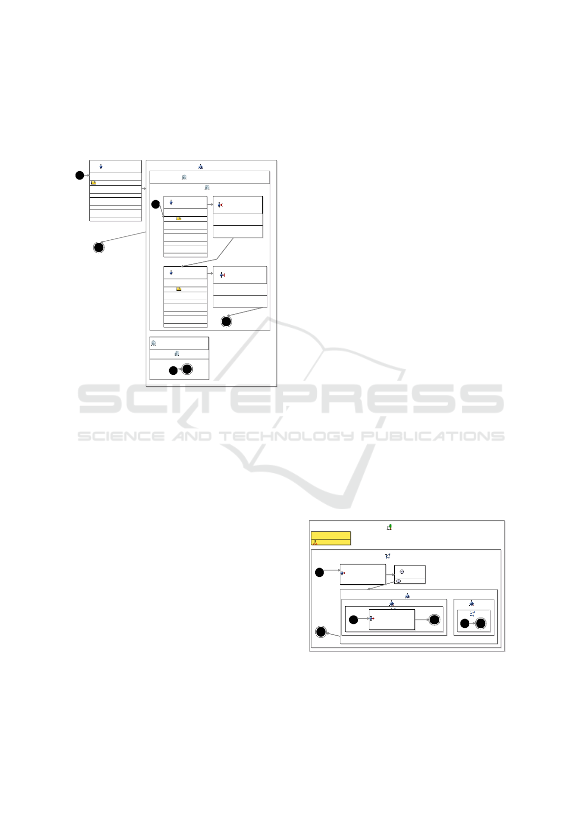
operation, its transformation result is merged in the
SEFF. The last example is the mapping of UML call
operation to API operation. Since it is a call to an
external component representing API, it is mapped to
the PCM external call action.
<<InternalAction>>
validate
ResourceDemand
IntPMF[(1;0.1)(5;0.9)] <CPU>
FailureOccurenceDescription
InfrastructureCall
ResourceCall
<<Branch>>
BranchAction1
<<ProbabilisticBranchTransition>>
ProbabilisticBranchTransition1
0.8
<<InternalAction>>
setQuery
ResourceDemand
1 <CPU>
FailureOccurenceDescription
InfrastructureCall
ResourceCall
<<ExternalCallAction>>
findOne
Hibernate.findOne
InputVariableUsageCompartme
nt
OutputVariableUsageCompartm
ent
<<InternalAction>>
setRfq
ResourceDemand
1 <CPU>
FailureOccurenceDescription
InfrastructureCall
ResourceCall
<<ExternalCallAction>>
save
Hibernate.save
InputVariableUsageCompartment
OutputVariableUsageCompartment
<<ProbabilisticBranchTransition>>
ProbabilisticBranchTransition2
0.2
Figure 4: PCM SEFF example.
Subsequent transformation creates a PCM system
model. It adds a PCM system assembly entity and
system-provided interfaces, which publish operations
invoked by a scenario behavior in a usage model.
Next, the system assembly is filled with components’
assembly contexts connected via components inter-
faces. An assembly context of a component requiring
an interface is connected with an assembly context of
a component providing the interface. There is always
only one possible connection since only one compo-
nent provides a given interface. The transformation
is straightforward, and for brevity, the transformation
pseudo-code is not presented in the paper.
Succeeding transformation creates a PCM alloca-
tion model, which has information on the assemblies’
allocation to resource containers. The allocation is
made concerning the deployment specification pro-
vided in the PSM-Inst model. The transformation
is straightforward, and for brevity, the transformation
pseudo-code is not presented in the paper.
Finally, UML PIM’s use-cases are transformed
into a PCM usage model. A new PCM Usage scenario
is added for each pair of an actor and a use-case, it
contains a workload specification and a scenario be-
havior. Because of the space limits, the transforma-
tion pseudo-code is not presented in the paper.
The scenario behavior is generated by moving
through a use-case’s activity, from node to node (ac-
tion nodes, decision nodes) via edges within an ac-
tor’s partition. An action node within the actor’s par-
tition is mapped to PCM delay (thinking) action in
the PCM scenario. For a decision node, a correspond-
ing PCM Branch node is added, and its alternative
sub-scenarios are filed by mapping for each outgo-
ing flows of the decision node. A PCM entry-level
system call of corresponding (through tracing) oper-
ation is made when there is a transition outside the
actor partition. Next, the graph continued within sys-
tem partitions is explored to check if and in which
places it transits back to the actor partition. If there is
no return, then it is assumed that the scenario is fin-
ished. When there is a single return to a node within
the actor’s partition, the movement through nodes and
edges within the partition is continued, starting from
the return node. When it returns to multiple nodes, a
PCM branch node is added, and for each return, an al-
ternative scenario is created. For the sake of simplic-
ity, we are considering only acyclic graphs. Because
of the space limits, the transformation pseudo-code is
not presented in the paper.
An example of applying this transformation on
Fig 1 is shown in Fig 5. Without losing generality,
only PCM scenario behavior is discussed. The first
node of the UML activity in Fig 1 is connected with
a node outside the actor’s partition, which is mapped
to a PCM entry-level system call. There is only one
return to the actor’s partition; thereby, the next node
in the partition is mapped. It is a UML action; hence
it is transformed to PCM delay action. The follow-
ing is a decision node; consequently, it is mapped to
PCM branch action. Two PCM branch transitions are
added. One includes a PCM entry-level system call,
and the other does nothing, i.e., end scenarios.
<<UsageScenario>>
Customer-SalesInquiry
<<OpenWorkload>>
Interarrival Time: 10
<<ScenarioBehaviour>>
SalesInquiry
<<EntryLevelSystemCall>>
InitRFQ
SalesREST.initEntryRFQ
<<Delay>>
Delay1
Delay Time: 60
<<Branch>>
decisionNode1
0.9
<<EntryLevelSystemCall>>
EntryRFQ
SalesREST.entryRFQ
0.1
Figure 5: PCM Usage Scenario Behavior - an example.
ENASE 2022 - 17th International Conference on Evaluation of Novel Approaches to Software Engineering
534

4 CONCLUSIONS
We discuss Palladio’s performance models generation
from MDA models, i.e., PSM and PIM. The PIM
is a platform-independent functional specification in
UML and is extended by performance characteristics
in the UML MARTE Profile. The PSM models, given
in the UML, provide implementation details and have
performance characteristics of deployment nodes in
MARTE.
We introduce the transformations of such PIM
and PSM models into PCM models, i.e., PCM Re-
source Environment, Repository, System, Allocation,
and Usage models. However, the transformations do
not fully transform performance characteristics, e.g.,
PCM parameters and data size are not considered, nei-
ther mapping MARTE performance statements into
PCM StoEx is. The transformation provides structure
and behavior documentation of a system in the PCM,
which has default performance characteristics.
Future work is to enhance the transformation by
mapping PIM and PSM performance characteristics
into PCM. In particular, MARTE statements have to
be mapped to PCM StoEx statements. Moreover,
the transformation should derive some performance
characteristics, e.g., generate a loop repetition num-
ber from data characteristics. Another task is to
provide transformation support for concurrency pro-
gramming. Finally, the transformation should be im-
plemented.
REFERENCES
Ameller, D., Franch, X., and Gómez (2021). Dealing with
non-functional requirements in model-driven develop-
ment: A survey. IEEE Transactions on Software En-
gineering, 47(4):818–835.
Chudzik, K., Gall, D., and Huzar, Z. (2011). Szere-
gowanie zada
´
n w oszacowaniu wymaga
´
n wydajno
´
s-
ciowych modelu psm. In Projektowanie, analiza i
implementacja systemów czasu rzeczywistego : praca
zbiorowa, pages 17–28. Wydawnictwa Komunikacji i
Ł ˛aczno
´
sci, Warszawa.
Cortellessa, V., Marco, A. D., and Inverardi, P. (2007a).
Integrating performance and reliability analysis in a
non-functional MDA framework. In Fundamental Ap-
proaches to Software Engineering, 10th International
Conference, FASE 2007, volume 4422 of Lecture
Notes in Computer Science, pages 57–71. Springer.
Cortellessa, V., Marco, A. D., and Inverardi, P. (2007b).
Non-functional modeling and validation in model-
driven architecture. In 2007 Working IEEE/IFIP Con-
ference on Software Architecture (WICSA’07), pages
25–25.
Falleri, J.-R., Huchard, M., and Nebut, C. (2006). Towards
a traceability framework for model transformations in
kermeta.
Gall, D. and Huzar, Z. (2010). Wymagania przepustowo
´
sci
w transformacji pim do psm. In Metody wytwarza-
nia i zastosowania systemów czasu rzeczywistego :
praca zbiorowa, pages 105–116. Wydawnictwa Ko-
munikacji i Ł ˛aczno
´
sci, Warszawa.
Hahner, S., Seifermann, S., Heinrich, R., Walter, M., Bu-
reš, T., and Hn
ˇ
etynka, P. (2021). Modeling data flow
constraints for design-time confidentiality analyses. In
2021 IEEE 18th International Conference on Software
Architecture Companion (ICSA-C), pages 15–21.
Hassane, O., Mustafiz, S., Khendek, F., and Toeroe, M.
(2020). A model traceability framework for network
service management. New York, NY, USA. Associa-
tion for Computing Machinery.
Kroß, J. and Krcmar, H. (2017). Model-based performance
evaluation of batch and stream applications for big
data. In 2017 IEEE 25th International Symposium on
Modeling, Analysis, and Simulation of Computer and
Telecommunication Systems (MASCOTS), pages 80–
86.
Mazkatli, M., Monschein, D., Grohmann, J., and Kozi-
olek, A. (2020). Incremental calibration of architec-
tural performance models with parametric dependen-
cies. 2020 IEEE International Conference on Soft-
ware Architecture (ICSA).
Object Management Group (2014). Model Driven Ar-
chitecture (MDA) Guide rev. 2.0. OMG Document.
https://www.omg.org/cgi-bin/doc?ormsc/14-06-01.
Object Management Group (2017). The Unified Model-
ing Language. OMG Document. https://www.omg.
org/spec/UML/.
Object Management Group (2019). UML Profile for
MARTE. OMG Document. https://www.omg.org/
spec/MARTE.
Reiche, F., Schiffl, J., and Weigl, A. (2021). Quantification
of correctness with palladio and key: Case study data.
Reussner, R., Becker, S., Burger, E., Happe, J., Hauck, M.,
Koziolek, A., Koziolek, H., Krogmann, K., and Ku-
perberg, M. (2011). The palladio component model.
Technical Report 14.
Reussner, R. H., Becker, S., Happe, J., Heinrich, R., Kozi-
olek, A., Koziolek, H., Kramer, M., and Krogmann,
K. (2016). Modeling and Simulating Software Archi-
tectures: The Palladio Approach.
Smith, C. U. and Williams, L. G. (2002). Performance so-
lutions: A practical guide to creating responsive, scal-
able software. USA. Addison Wesley Longman Pub-
lishing Co., Inc.
Walkowiak-Gall, A. and Gall, D. (2015). Pim-psm pattern-
aware transformations. In From requirements to soft-
ware : research and practice, pages 101–117. Polish
Information Processing Society, Warszawa.
From PIM and PSM with Performance Annotation to Palladio Models
535
