
On the Simulation of Electrochemistry Aspect of Electrochemical
Spark Micromachining Process
Anjali V. Kulkarni
a
Centre for Mechatronics, IIT Kanpur, Kanpur, UP, India
Keywords: COMSOL, Electrochemical Phase, Electrochemical Spark Micromachining Process, Multiphysics, Spark
Formation Cycle Ed.
Abstract: Electrochemical spark micromachining (ECSMM) process, an advanced machining process is investigated to
understand process mechanism. The material removal mechanism in ECSMM is a complex phenomenon due
to its multiphysics and transient nature. Experimental measurements of online current and voltage have been
performed simultaneously. Different sequential operational stages in one single spark cycle have been
identified in the light of the transient measurements. The Semiempirical electrical impedances during these
identified operational stages have been formulated and compared with those derived by using measured online
current and voltage data. Only the impedance results during electrochemical phase in a single spark cycle
have been reported here. In case of ECS, considering the kinetics at the electrolyte and electrode interfaces,
the effective equivalent circuit is derived. The charge transfer resistance in the equivalent circuit during the
electrochemical phase is found by performing impedance spectroscopy using COMSOL multiphysics
modeling software. For this 1-d model of the electrochemical process is developed using secondary current
distribution. It is for the first time that COMSOL study has been attempted in analyzing the physics behind
the material removal phenomenon mainly during the electrochemical operational phase of ECSMM. The
modeled and measured impedances show close similarities.
1 INTRODUCTION
Electrochemical spark micromachining (ECSMM)
process is an advanced machining process in which
sparking is responsible for machining of wide variety
of materials. The process is investigated in the holistic
approach to understand process mechanisms.
Material removal mechanism in particular is a
complex phenomenon due to its multiphysics nature.
The sparking during the machining process is not
continuous as it is conventionally identified; rather it
is a repetitively occurring discrete and complex
phenomenon. Complexity arises primarily due to the
presence of various physio-chemical phases involved
in forming the discrete sparking. Moreover
electrochemical systems are known to exhibit
complex non-linear behavior. These nonlinearities
arise due to electro hydro dynamism, ionic reactions,
bubble generation, their growth and their breakdown
phenomena, with material removal over a finite area
as a final result. The spark formation cycle is a series
of such activities. Also sparks are non-thermal in
a
https://orcid.org/0000-0001-5210-570X
nature as opposed to the theoretical assumption that
spark is a heat source for material removal to take
place. In the existent literature, spark energy is
considered to be of thermal nature. Also the thermal
analysis and material removal are considered to be
due to this thermal source (Basak & Ghosh, 1992;
Basak & Ghosh, 1996; Jain, Dixit & Pandey, 1999).
But in a separate transient temperature study using
pyrometer (Kulkarni, 2009), it has been found
experimentally that the spark is a non thermal
discharge. Through this study, it is established that
the process is similar to a repeated sparking/discharge
similar to that of the breakdown of the hydrogen gas
bubble isolating the tool tip from the surrounding
electrolyte. Consequent to this finding, electrical
impedance in each sequential stage of a single spark
cycle is modeled based on the physics of each stage
respectively. This semiempirical impedance is
compared against the impedance computed by taking
the ratio of the measured online, transient and
synchronized voltage and current data during single
spark formation (Kulkarni, 2017). The modeled and
172
Kulkarni, A.
On the Simulation of Electrochemistry Aspect of Electrochemical Spark Micromachining Process.
DOI: 10.5220/0011122500003274
In Proceedings of the 12th International Conference on Simulation and Modeling Methodologies, Technologies and Applications (SIMULTECH 2022), pages 172-177
ISBN: 978-989-758-578-4; ISSN: 2184-2841
Copyright
c
2022 by SCITEPRESS – Science and Technology Publications, Lda. All rights reserved

measured impedances show close similarities.
Findings of the impedance results during
electrochemical phase during a single spark cycle
have been reported here.
It is for the first time that COMSOL study has
been attempted in analyzing the physics behind the
mechanical removal phenomenon mainly during the
electrochemical operational phase/stage in working
of ECSMM. Hence no literature is available with the
research findings with which comparison of results
can be performed.
2 EXPERIMENTAL
The time varying online process current is measured
in synchronization with the machining supply voltage
using digital storage oscilloscope (DSO, Hameg
1008) by ‘resistive shunt method’. For this, a 1 Ω
resistance is connected in series with cathode (made
up of copper wire of diameter 100 µm with its tip
partially dipped in the NaOH electrolyte) and ground
of the power supply to the ECS cell. The time varying
voltage across this resistance is the direct measure of
the time varying process current. These synchronized
current and voltage waveforms are saved on the
control PC via RS 232 connectivity module of the
DSO. Each waveform contains 2000 samples of the
voltage and current readings. The current waveform
contains many spark cycles (Kulkarni, 2013;
Kulkarni, 2015).
3 SEQUENTIAL OPERATIONAL
PHASES OF ECSMM PROCESS
IN THE LIGHT OF ONLINE,
TRANSIENT CURRENT
The formation of spark happens through series of
chemical and physical processes. When a voltage
(enough to form spark) is applied across the
electrolyte cell (containing electrolyte with cathode
and electrode dipped partially in it with workpiece on
which the micromachining is intended), mainly
following series of events take place (Kulkarni, 2013;
Kulkarni, 2015):
1. Electrochemical phase giving rise to oxidation
and hydrogen gas generation.
2. Hydrogen and vapor bubbles formation,
coalescence and bubble growth during pool
boiling, slowly covering the tool tip.
3. Tool tip isolation, momentary ‘virtual switch
off’ phase.
4. Instantaneous generation of high electric field
which causes sparking due to hydrogen
breakdown.
5. Drifting of energetic electrons towards the
workpiece due to potential gradient and
subsequent material removal from the
workpiece kept near the tool tip due to this
‘electron gun’.
6. Reestablishment of tool-electrolyte contact
leading to a ‘virtual switch on’ phase.
7. steps 1-6 begin all over again.
Following section establishes the theoretical
background behind electrochemical phase operation.
It also identifies major electrical parameters
responsible for the instantaneous current contribution
in that phase of operation during the single spark
formation.
3.1 Electrochemical Phase
When the machining supply to the electrolyte cell is
applied in the proper polarity, (i.e. positive terminal
connected to graphite anode and negative terminal to
copper cathode) electrochemical action starts.
Electrochemical reactions that occur at the electrode–
electrolyte interface continuously supply electrons
from cathode to solution and solution to anode. This
is called as the ‘migration’ state of the ECSMM
process and causes the electronic current. The anodic
and cathodic reactions occur together with reduction
in electrolyte. These liberated positive ions move
towards cathode and negative ions move towards
anode and causes the ionic current. Ionic and
electronic current together form the average current
and it is of the order of 100 – 200 mA as is measured.
Major other (transient) current contributing circuit
elements during this phase are investigated in the next
section.
3.2 Current Contributing Elements
during Electrochemical Phase
Electrolyte resistance, double layer capacitance,
polarization resistance, and charge transfer resistance
are the elements those contribute to the overall
electrochemical reactions during electrochemical
phase and hence the instantaneous current, as
described below.
On the Simulation of Electrochemistry Aspect of Electrochemical Spark Micromachining Process
173
3.2.1 Electrolyte Resistance
In an electrochemical cell, bulk solution resistance is
a significant factor. In this experimental situation,
estimation of NaOH solution resistance is estimated
by taking the inverse of the conductivity. But in real
situations, it depends on the geometry of the solution
(container), its temperature, etc. It is found that the
effect of electrolyte resistance is dominant during
electrochemical and bubble growth phases only.
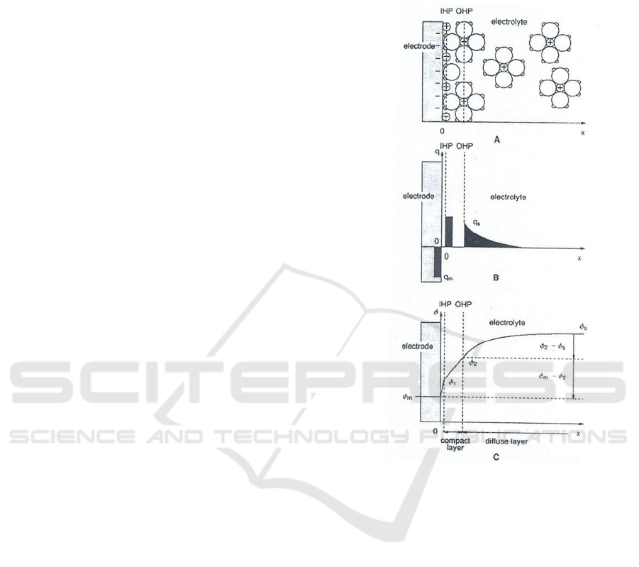
3.2.2 Double Layer Capacitance
An electrical double layer exists on the interface
between an electrode and its surrounding electrolyte.
This double layer is formed as ions from the solution
‘stick on’ the electrode surface. The charged
electrode is separated from the charged ions. The
separation is very small, of the order of angstroms.
Charges separated by an insulator form a capacitor.
Practically the capacitance such formed is of the order
of 20 to 60 µF per cm
2
area of the electrode. Figure 1
shows the process of double layer formation. All the
electrolyte processes take place at the electrode-
electrolyte interface. The structure of the double layer
is similar to an electrical capacitor formed by a
dielectric of thickness of about an ionic radius, i.e. 50
nm. Figure 1 A shows the formation of inner
Helmholtz plane (IHP), outer Helmholtz plane (OHP)
and the electrode with an excess of negative charge.
Figure 1 B shows the localization of the excess
charges and Figure 1 C shows the potential gradient
formed.
3.2.3 Polarization Resistance
Whenever the potential of an electrode is forced away
from its value at ‘open-circuit’, it is referred to as
polarizing the electrode. When an electrode is
polarized, it causes current to flow through
electrochemical reactions that occur at the electrode
surface. The amount of current is controlled by the
kinetics of the reactions and the diffusion of reactants
both towards and away from the electrode. In the case
of ECS cell, the diffusion of reactants is absent.
Hence only the kinetics of the reactions plays the
major role.
3.2.4 Charge Transfer Resistance
Another resistance is formed by a single kinetically
controlled electrochemical reaction. In the case of
ECS, the reactions occurring at the cathode-
electrolyte interface are of concern and form the basis
of the analysis. The kinetics of the charge transfer
depends on the kind of reaction, the concentration of
reactants, the potential, and many other factors.
Figure 1: This Process of the double layer formation
(Kulkarni, 2013).
Figure 2 shows the various potential drops formed
during a general electrochemical cell with an applied
supply voltage. The supply voltage overcomes the
following potentials:
• The electrode potential,
• The activation over potential,
• Ohmic potential drop,
• Concentration over potential ( not of much
relevance in ECS) and
• The potential due to resistance of electrolyte.
SIMULTECH 2022 - 12th International Conference on Simulation and Modeling Methodologies, Technologies and Applications
174
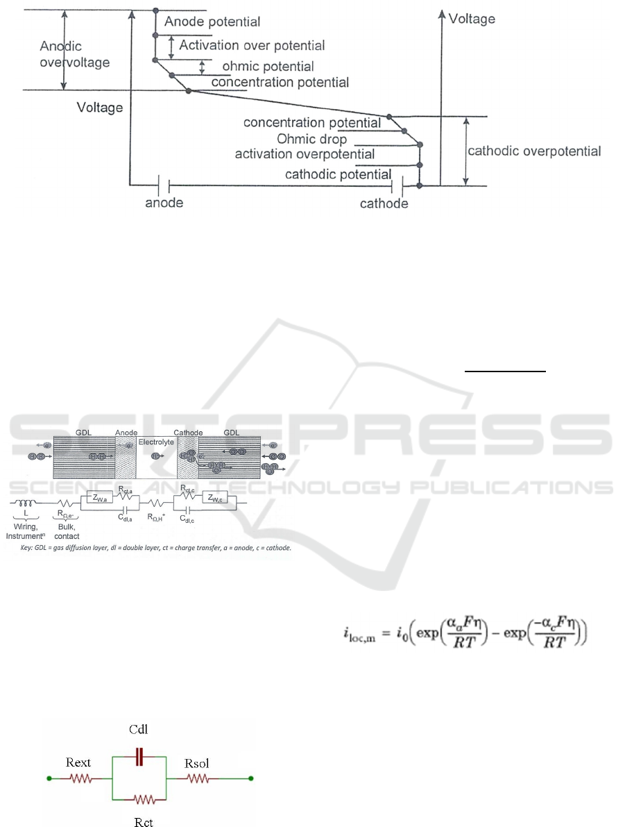
Figure 2: Various potential drops during a general electrochemical cell (Kulkarni, 2013).
4 EQUIVALENT CIRCUIT
DURING ELECTROCHEMICAL
PHASE
Figure 3 shows the circuit parameters for a general
electrochemical cell. In the case of ECS, the kinetics
at the anode electrode is neglected due to the non
consuming electrode material.
Figure 3: Circuit parameters for a general electrochemical
cell (Kulkarni, 2013).
4.1 Time Varying Impedance during
Electrochemical Phase
Neglecting the wiring inductance, bulk contact
resistance, Z
w
, the effective equivalent circuit during
electrochemical phase is as shown in Figure 4.
Figure 4: Electrical equivalent circuit in the electrochemical
stage of ECS process.
The time varying impedance Z(t) during
electrochemical phase (neglecting R
ext
) is shown by
equation (1) below, where, Rsol is Electrolyte
resistance, Cdl is Double layer capacitance, and Rct
is Charge transfer resistance
Zt 𝑅𝑠𝑜𝑙
𝑅𝑐𝑡
1
𝑗
𝜔𝑅𝑐𝑡𝐶𝑑𝑙
(1
)
Butler-Volmer and Tafel (an equation in
electrochemical kinetics relating the rate of an
electrochemical reaction to the overpotential)
expressions (https://www.gamry.com/application-no
tes/EIS/basics-of-electrochemical-impedance-spectr
oscopy/, retrieved 26 May 2012) are used to derive
electrode kinetics for the charge transfer reactions.
In the Secondary Current Distribution interface,
the electrochemical reactions are described as a
function of the overpotential. The interface uses
several relations for the charge transfer current
density and the overpotential. The most general
expression is of Butler-Volmer type:
(2
)
where i
loc,m
denotes the local charge transfer current
density for reaction m, i
0
the exchange current
density, α
a
the anodic transfer coefficient, α
c
the
cathodic charge transfer coefficient, F the Faraday
constant, and R the universal gas constant. On a single
electrode the Tafel equation can be stated as:
η = ± A × log
10
(i/i
0
)
(3
)
where the plus sign under the exponent refers to an
anodic reaction, and a minus sign to a cathodic
reaction, and η is overpotential (V), A is "Tafel
slope", (V), i is current density (A/m
2
) and I
0
is
"exchange current density" (A/m
2
).
On the Simulation of Electrochemistry Aspect of Electrochemical Spark Micromachining Process
175
Butler-Volmer (B-V) equation has been used to
estimate the charge transfer resistance with
appropriate boundary conditions. The interfaces
define two dependent variables of potentials. The
conduction of current in the electrolyte is assumed to
take place through transport of ions while electrons
conduct the current in the electrode.
4.2
Impedance
Spectroscopy using
COMSOL 4.2 Multiphysics
The ‘electrochemical model’ in COMSOL 4.2
software is used to solve 1-d simulation of the
electrode kinematics in the ECS cell using the
‘secondary current distribution’ physics built-in in
COMSOL (https://doc.comsol.com/5.3/doc/com.com
sol.help.echem/ElectrochemistryModuleUsersGuide.
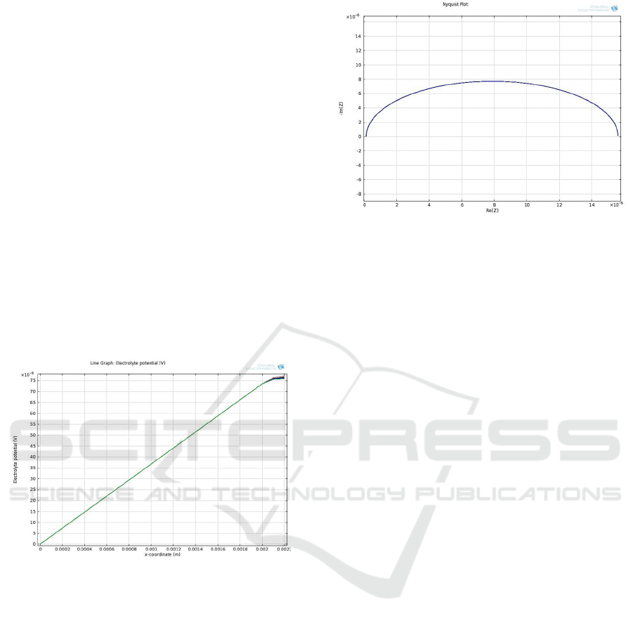
pdf, retrived on 26 May 2012). Figure 5 shows the
simulated electrolyte potential distribution in the cell.
The electrolyte voltage in the cell is seen around 75 x
10
-6
V at a distance of 22 µm away from the cathode.
Figure 5: Electrolyte potential distribution in the cell
(Kulkarni, 2013).
Figure 6 gives the Nyquist plot generated by
COMSOL software by using the perturbation current
of 5 mA. It gives Rct around 14.8 x 10
-6
Ω. The Rct x
Cdl time constant is very small and is of the order of
few hundreds of ns. That means the electrochemical
reactions are very fast. The hydrogen bubble growth
due to pool boiling phenomenon soon takes over
(which is not the scope of this paper).
Figure 6: Nyquist plot generated by the COMSOL 4.2
software (Kulkarni, 2013).
5 CONCLUSIONS
• The important intermittent sequential phases of
the process have been identified and analyzed.
Repeated formations of spark happen through
series of chemical and physical processes in
phases. These are: electrochemical action,
bubble formation, coalescence and growth of
bubble during pool boiling slowly covering the
tool tip, tool tip isolation leading to a momentary
‘virtual switch off situation, instantaneous
application of high electric field causes sparking
of hydrogen breakdown, reestablishment of tool-
electrolyte contact leading to ‘virtual switch on’
situation, drifting of energetic electrons towards
the workpiece due to potential gradient.
• The instantaneous process current comprises of
current due to these sequential events. The
electrical impedance during each phase of
operation varies. Of these phases, the
electrochemical action phase is the fastest
process.
• Charge transfer kinetics at anode electrode is
neglected. This is minimized by the design of the
anode electrode.
• The charge transfer resistance in the equivalent
circuit during the electrochemical phase is found
by performing the impedance spectroscopy. It is
done using COMSOL Multiphysics modeling
software. For this 1-d model of the
electrochemical process is developed using
secondary current distribution. The time constant
due to the parallel combination of the double
layer capacitor and the charge transfer resistance
is of the order of thousands of ns. That means
the formation of the double layer capacitance and
SIMULTECH 2022 - 12th International Conference on Simulation and Modeling Methodologies, Technologies and Applications
176

charge transfer resistance happens within
thousands of ns time.
ACKNOWLEDGEMENTS
I am indebted to my guide Prof. V. K. Jain (retired,
ME Dept. IIT Kanpur) for his guidance throughout
my academic carrier.
Thanks are due to the staff at Manufacturing
Science Lab and the Centre for Mechatronics at IIT
Kanpur in setting up the experiments and carrying out
the experimental work.
The grant (SR / S3 / MERC-079/2004) from
Department of Science and Technology, New Delhi
is gratefully acknowledged.
REFERENCES
Basak, F., and Ghosh, A. (1992). Mechanism of material
removal in electrochemical discharge machining: a
theoretic model and experimental verification. J.
Mater. Process. Technology, vol.71, pp. 350–359.
Basak, F., and Ghosh, A. (1996). Mechanism of spark
generation during electrochemical discharge
machining: a theoretical model and experimental
investigation. Jr. of Materials Processing Technology,
vol. 62 pp.46-53.
Jain, V. K. Dixit, P. M., and Pandey, P. M. (1996). On the
Analysis of Electrochemical Spark Machining Process.
Int. J. Mach. Tools & Manufacture, vol. 39, No. 1, pp.
165 – 186.
Kulkarni, A. V. (2009). Systematic analysis of
electrochemical discharge process. Int. J. Machining
and Machinability of Materials, 6, ¾, pp 194-211.
Kulkarni, A. V. (2017). Electrical Impedance Modeling of
Electrochemical Spark Micromachining Process. In
Mathematical Concepts and Applications in
Mechanical Engineering and Mechatronics, IGI Global
publisher, pn 246-270, (https://lnkd.in/fhwfYvN).
Kulkarni A. V. ( 2013). Performance Investigations into
Microfabrication using Electrochemical Spark. Ph.D.
thesis, GBTU, Lucknow.
Kulkarni A. V. and Jain V. K. (2015). Design and
Development of an Electrochemical Spark Micro
Manufacturing Equipment. International Journal of
Mechanical Engineering and Robotics Research.
Vol.4, No. 4, pp. 368-372, DOI: 10.18178/
ijmerr.4.4.368-372.
Kulkarni A. V. (2012). Micromachining Techniques for
Fabrication of Micro and Nano Structures, ISBN 978-
953-307-906-6, edited by Mojtaba Kahrizi, pp 235-252.
https://www.gamry.com/application-notes/EIS/basics-of-
electrochemical-impedance-spectroscopy/
https://doc.comsol.com/5.3/doc/com.comsol.help.echem/E
lectrochemistryModuleUsersGuide.pdf
On the Simulation of Electrochemistry Aspect of Electrochemical Spark Micromachining Process
177
