
Safe Robotized Polishing of Plastic Optical Fibers for Plasmonic Sensors
Francesco Arcadio, Marco Costanzo, Giulio Luongo, Luigi Pellegrino, Nunzio Cennamo
and Ciro Natale
Dipartimento di Ingegneria, Universit
`
a degli Studi della Campania ”Luigi Vanvitelli”, Via Roma 29, Aversa, Italy
Keywords:
Human-robot Collaboration, Workspace Monitoring, Compliance Control, Plasmonic Optical Fiber
Biosensors.
Abstract:
Plastic optical fibers (POFs) biosensors are getting widespread in a number of application fields owing to
their low cost, high performance, and for their extreme flexibility in terms of detection ability of a large
number of specific substances in different matrices. A specific category of such sensors are those based on
the surface plasmon resonance (SPR) phenomenon, which can be made very specific by suitable integration
with a biological or chemical molecular recognition element (MRE), specifically designed for binding with the
desired substance (the analyte). Despite the flexibility of the SPR-POF sensors, their production is still difficult
to automate on a large scale because of the special polishing process of the plastic optical fiber. Such a process
is currently performed by a human trained operator who rubs the surface of a short fiber segment against a
sandpaper sheet by following an 8-shaped path while exerting a specific force in the direction normal to the
contact surface. The present paper proposes the adoption of a collaborative robot programmed to perform the
same task based on the data acquired from the human operator. To ensure the safe use of the robotic cell by
operators who share the same workspace of the robot, the system is endowed with a workspace monitoring
system that ensures the polishing task execution while minimizing the possible occurrence of collisions with
human operators by suitable exploiting the kinematic redundancy of the robot.
1 INTRODUCTION
Highly sensitive plasmonic POF probes, com-
bined with specific molecular recognition elements
(MREs), can be obtained by exploiting modified
POFs to obtain the interaction with the analyzed
medium directly. For instance, a D-Shaped region
must be realized to deposit a metal nanofilm, use-
ful to excite the SPR phenomenon in this sensing
area. The SPR phenomenon is a label-free technique
where MREs, coupled to a metal surface (usually gold
nanofilms), selectively recognize and capture the sub-
stance of interest, producing a local change in the re-
fractive index at the metal surface interface by chang-
ing the resonance condition. This sensing approach,
based on SPR-POF probes combined with MREs, can
be used in several applications, such as medical di-
agnostics, environmental monitoring, industry, food
safety, and security (Cennamo et al., 2021). The au-
thors have combined the same SPR-POF platforms
with different kinds of MREs, such as antibodies, ap-
tamers, and molecularly imprinted polymers (MIPs),
by obtaining interesting detection ranges in many ap-
plications. The limit of this sensing approach is the
production process of the POF platforms because it
is based on a polishing step, currently handmade.
This limit yields inefficient process control to realize
very similar sensors or to change their performances;
hence, this kind of sensor cannot be produced on an
industrial scale.
Automation of such a production process might
be performed through the design of specific polishing
machines or through a flexible automation approach
like the use of robots. In the former case, the rigid-
ity of the automation solution might be characterized
by a low return on investment, since the scale of the
automation system highly depends on the actual mar-
ket demand of the sensor, which is very difficult to
forecast for a new product. Therefore, such a rigid
solution might be risky, especially for a startup. This
motivated the approach proposed in the paper, which
explores the possibility to adopt a modern collabora-
tive robot (cobot) that can safely work in a highly dy-
namic environment shared with human operators (Na-
tale, 2019). Programming of cobots is usually done
by hand guidance but in the application at hand the
motion trajectory the robot has to follow is very spe-
cific and it can be easily programmed by resorting to
a motion primitive (Siciliano et al., 2009). Further-
more, following the given trajectory is not enough
to carry out the polishing task properly, but a suit-
able normal force should be exerted during the mo-
Arcadio, F., Costanzo, M., Luongo, G., Pellegrino, L., Cennamo, N. and Natale, C.
Safe Robotized Polishing of Plastic Optical Fibers for Plasmonic Sensors.
DOI: 10.5220/0011123100003271
In Proceedings of the 19th International Conference on Informatics in Control, Automation and Robotics (ICINCO 2022), pages 361-368
ISBN: 978-989-758-585-2; ISSN: 2184-2809
Copyright
c
2022 by SCITEPRESS – Science and Technology Publications, Lda. All rights reserved
361
tion to ensure a proper abrasion of the plastic fiber
cladding. This requires a force/motion control algo-
rithm (Villani, 2020) and the approach proposed in
this paper is inspired to (Haddadin et al., 2009), which
is specifically suitable for elastic joint manipulators.
A relevant aspect of any force control robotic appli-
cation is the specification of the desired force profile.
This work followed the well-known programming by
demonstration strategy (Calinon, 2018); a human op-
erator performs the task which has to be repeated by
the robot and the necessary data are acquired. In this
case, the contact force profile is recorded and a Gaus-
sian Mixture Model is learned and then used to gen-
erate the force profile to track with the force control
loop. The robot control system is eventually com-
pleted with a safe reaction strategy to the presence
of human operators close to the robot arm. The robot
workspace is constantly monitored by a RGB-D cam-
era which track the skeletons of all human operators
inside the workspace. The skeleton data are then used
to compute the minimum distance from the robot that
is the basis for a virtual repulsive action on the robot
elbow which pushes this far away from the human op-
erator. As soon as the operator goes out the robot
worksapce, the elbow is brought to its nominal con-
figuration by an elastic torque.
The collaborative robotic cell has been tested for
the production of 10 sensor platforms, which have
then been tested by using several water-glycerin solu-
tions with different refractive indices. The results in
terms of sensitivity and full width at half maximum
of the resonance curve of all sensors demonstrate that
the robotized polishing process ensures the expected
quality and relieves the human operator from a rele-
vant physical burden.
2 PRODUCTION PROCEDURE
OF THE SPR-POF SENSOR
Intrinsic POF plasmonic sensors, where the mod-
ified POF interacts with the analyzed medium di-
rectly, have been presented to exploit different ap-
proaches, such as making a D-shaped POF sensing
region. More specifically, about ten years ago, Cen-
namo et al. have presented a very simple to realize,
low-cost, and high sensitive SPR sensor in Plastic Op-
tical Fibers (Cennamo et al., 2011). To realize this
SPR-POF sensor are necessary only three steps. In
the first step, the optical fiber is fixed in a resin block
to remove the cladding and part of the core in order to
realize a D-shaped POF sensing area. These polishing
steps are handmade exploiting two different polishing
papers: a 5µm polishing paper and a 1 µm polishing
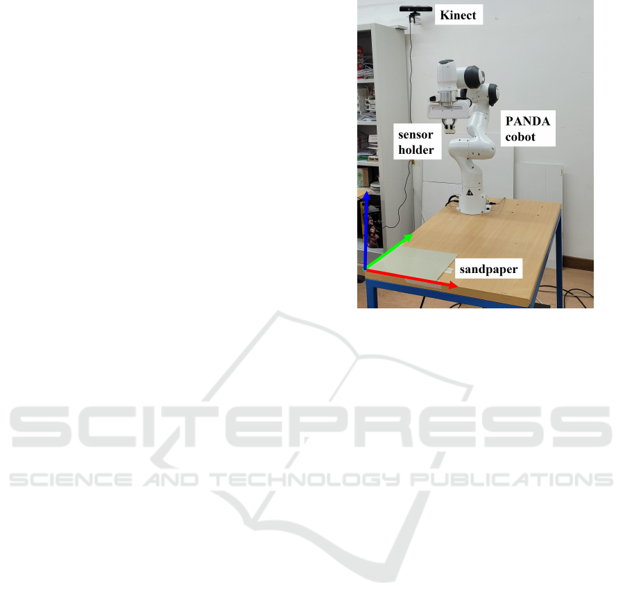
Figure 1: The collaborative robot for sensor polishing with
the reference desk frame (RGB convention).
paper. The realized D-shaped sensing region is about
10mm in length. In the second step, a thin buffer layer
(e.g. a layer of Microposit S1813 photoresist), a layer
with a refractive index major than the core of the POF,
is deposited by a spin coater, to improve the interac-
tion between the light and the plasmonic (SPR) phe-
nomenon. Finally, in the third step, a gold nano-film
(about 60 nanometers) is deposited by a sputter coater.
The used POF has a PMMA core of 980µm and a flu-
orinated polymer cladding of 10 µm (1,000 µm in total
diameter). The experimental results reported in (Cen-
namo et al., 2011) have indicated that the configura-
tion with the buffer layer exhibits better performance
in terms of detectable refractive index range and of
full width at half maximum of the SPR curve. In this
work, sensor configurations without the buffer layer
will be realized and tested. The buffer layer has been
not used to test the automatic polishing process.
3 THE COLLABORATIVE CELL
This section describes the approach used to automate
the polishing task of the SPR-POF sensor through the
collaborative work cell shown in figure 1, in which
a seven-joint robot and humans can work together.
A Cartesian force/compliance control algorithm has
been used to carry out the polishing task. A depth
camera has been used to detect and avoid collisions
with human operators in the robot workspace.
ICINCO 2022 - 19th International Conference on Informatics in Control, Automation and Robotics
362
3.1 Perception System
The depth camera is a Microsoft Kinect v1 (see Fig-
ure 1). To correctly use the data provided by the cam-
era in the robot control algorithm, it is necessary to
perform the extrinsic calibration procedure aimed at
determining the homogeneous transformation matrix
T
b
c
representing the pose of the camera frame with
respect to the robot base frame. The following cali-
bration procedure has been used:
1. A reference frame on the desk has been chosen as
shown in Fig. 1.
2. Using an algorithm for the reconstruction of Point
Cloud, the following three points have been iden-
tified: the origin of the desk frame, a point of the
x axis and a point of the y axis of the desk frame.
The three points were then used to compute the
homogeneous transformation matrix T
c
desk
.
3. By positioning the robot through hand guidance
and calculating the end-effector position through
the direct kinematics, the following three points
have been identified: the origin of the desk frame,
a point of the x axis and a point of the y axis of the
desk frame. The three points were then used to
compute the homogeneous transformation matrix
T
b
desk
.
4. The homogeneous transformation matrix T
b
c
is
eventually computed as
T
b
c
= T
b
desk
(T
c
desk
)
−1
(1)
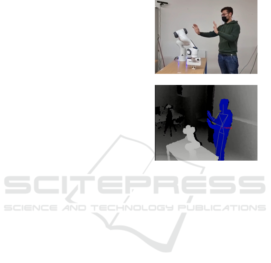
3.2 Skeleton Tracking
Realizing a safe Human Robot Collaboration (HRC)
application requires a fast tracking algorithm which
detects human operators in real time. For this pur-
pose, the NiTE’s skeleton tracking algorithm has been
used. OpenNI/NiTE is a well known open-source
framework that provides a set of APIs for body mo-
tion tracking that work with several perception sys-
tems, including the Microsoft Kinect v1 (PrimeSense,
2011). The algorithm tracks 15 joints for each oper-
ator in the scene in the form of a skeleton (see figure
2b) and returns the 3D position for each one of them:
s
c
i,k
, k = 1, 2,.. .,15, i = 0, ... ,N, being N the num-
ber of operators, that is 0 if no operator is detected
in the scene. These positions are then used to com-
pute the minimum distance d between a point on the
robot elbow with position p
b
E
and all human opera-
tors joints. Spheres were used to incorporate the un-
tracked body portions and improve safety: a sphere
with radius r
1
= 0.14 m was chosen for the head joint,
(a) Human operator close to the robot.
(b) Kinect depth view with the skeleton overlay.
Figure 2: The perception system for workspace monitoring.
a sphere with radius r
E
= 0.11m for the robot el-
bow and spheres with radius r
j
= 0.07 m for the other
joints of the skeletons. Once every captured joint po-
sition is expressed in the robot base frame through the
homogeneous transformation matrix T
b
c
, the compu-
tation of d proceeds as follows
1. For each operator i in the scene, compute the min-
imum distance from the robot elbow and the hu-
man joints
d
i
= min
k
d(p
b
E
,s
b
i,k
) i = 1,. .., N (2)
where d(p
b
E
,s
b
i,k
) is computed as
d(p
b
E
,s
b
i,k
) =
(
kp
b
E
−s
b
i,k
k−(r
E
+ r
i
) if r
E
+ r
i
≤ kp
b
E
−s
b
i,k
k
0 otherwise
2. Determine the minimum distance d as the smallest
distance among the previously calculated ones
d = min
i
d
i
(3)
To correctly use the computed distance d in the con-
trol law of Section 3.3, the position s
b
n,m
of the closest
joint (m) of the closest operator (n) is stored.
Safe Robotized Polishing of Plastic Optical Fibers for Plasmonic Sensors
363

3.3 Robot Control System
The torque control law proposed in this paper consists
of three terms, i.e.,
τ (t) = τ
1
(t) + τ
2
(t) + τ
3
(t). (4)
The first term τ
1
(t) corresponds to the
force/compliance control law, a hybrid force control
scheme, which provides the robot with the capability
to track a motion trajectory along the directions
lying on the plane of the sandpaper while following
a force profile in the orthogonal direction. In detail,
the first control torque has been selected inspired by
the passivity approach proposed in (Schindlbeck and
Haddadin, 2015)
τ
1
(t) = J
T
(q(t))
h
K
p
˜x(t) + K
p
f
(h
d
(t) −h
e
(t))
+K
i
f
Z
t
0
(h
d
(σ) −h
e
(σ))dσ + K
d
˙
˜x(t)
(5)
where ˜x(t) = x
d
(t)−x
e
(t) is the pose tracking error,
K
p
∈R
6x6
and K
d
∈R
6x6
are the position and damp-
ing gain positive definite diagonal matrices, K
p
f
∈
R
6x6
and K
i
f
∈ R
6x6
are diagonal positive definite
matrices for the proportional and the integral control
action on the force error, respectively, J(q) is the ma-
nipulator Jacobian, consistent with the chosen orien-
tation representation, and h
d
(t) = (f
T
d
(t) 0
T
)
T
and
h
e
(t) = (f
T
e
(t) µ
T
e
(t))
T
are the desired and the mea-
sured wrench vectors at the end effector, respectively.
Note that, friction and gravity compensation terms are
not reported since they are applied at low-level by the
control interface of the robot.
The second term τ
2
(t) is designed to endow the
collaborative robot with a collision avoidance behav-
ior. Time dependence will be omitted for brevity. The
term τ
2
consists of two contributions:
1. τ
2
rep
. This term corresponds to a repulsive wrench
h
r
, computed starting from the minimum distance
d, so as to generate an internal motion that moves
the elbow away from the operator. The repulsive
wrench is defined as
h
r
= (f
T
r
0
T
)
T
,
where f
r
has been selected inspired by (Flacco
et al., 2012) as follows
f
r
=
F
max
1 + e
α
2
ρ
d−1
u (6)
where F
max
is the maximum admissible magni-
tude, α is a shape factor, ρ represents the distance
at which the magnitude of the repulsive force will
approach zero and u is the unit vector along the
direction defined by
u =
p
b
E
−s
b
n,m
kp
b
E
−s
b
n,m
k
The torque τ
2
rep
is obtained by premultiplying the
repulsive wrench by the transpose of the Jacobian
J
4
(q
1
,q
2
,q
3
,q
4
) of the manipulator consisting of
the first 4 links only, i.e.,
τ
2
rep
=
J
T
4
(q
1
,q
2
,q
3
,q
4
)
O
3×6
h
r
(7)
2. τ
2
el
. This term generates an elastic action so as to
bring back the manipulator in the high-elbow con-
figuration when no operator is in the workspace.
τ
2
el
= K
el
(q
HE
−q), (8)
where K
el
∈ R
7x7
is the stiffness matrix, q
HE
is
a high-elbow configuration and q is the current
configuration of the manipulator.
To ensure that the primary task is performed accu-
rately even in the presence of an operator in the
collaborative workspace, the repulsive and elastic
torques have been projected into the null space of
the transpose of the dynamically consistent pseudo-
inverse of the Jacobian
¯
J
T
(q) (Khatib, 1987), i.e.,
τ
2
=
I −J
T
(q)
¯
J
T
(q)
τ
2
rep
+ τ
2
el
(9)
The third term τ
3
(t) is a compensation term,
which ensures that the projected torque τ
2
(t) does not
contribute to the end-effector acceleration, namely
τ
3
= −B(q)
¯
J(q)
˙
J(q, ˙q) ˙q (10)
4 LEARNING FROM THE
HUMAN OPERATOR
The polishing task requires a long training phase of
the human operator, not only in terms of the specific
motion trajectory required to rub the optical fiber on
the sandpaper, but also in terms of the normal force
profile applied during the polishing. Therefore, we
decided to transfer this skill from a trained human op-
erator to the robot through a learning by demonstra-
tion approach (Calinon, 2018).
The first step of the learning from demonstration
process is that of data acquisition. If it is well known
that the motion trajectory to follow during the pol-
ishing process is a 8-shaped figure (Cennamo et al.,
2011), no information on the most suitable normal
force profile can be found in the literature. Thus, the
actual force applied by a well-trained human operator
ICINCO 2022 - 19th International Conference on Informatics in Control, Automation and Robotics
364
was acquired during a set of polishing trials through
a 6D force sensor mounted on an handle suitably de-
signed to keep the sensor platform hosting the POF in
contact with the sandpaper.
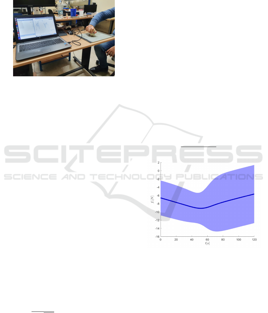
Figure 3: The human observation system.
The setup for the human observation depicted in
Fig. 3 includes a Robotous RFT-40 force/torque sen-
sor connected to a Ubuntu laptop via USB, so as to
acquire the contact force along the normal to the sur-
face at a rate of 200Hz.
4.1 Contact Force Planning
The desired force profile f
d
(t) used in the robot
controller presented in Section 3.3 is generated by
a Gaussian Mixture Regression (GMR), which was
trained on the basis of the force data set acquired dur-
ing four polishing trials, each 2minutes long. In par-
ticular, the chosen Gaussian Mixture Model (GMM)
of K Gaussian components (Calinon, 2018) is defined
by the probability density function
p(ξ) =
K
∑
k=1
p(k)p(ξ|k), (11)
where ξ is the generic data point of the data set, p(k)
is the prior and p(ξ|k) is the conditional probability
density function. A temporal regression problem for
the normal force trajectory has to be solved, hence
each data point is a couple ξ = (t f
z
)
T
∈ R
2
and the
parameters of the model are {p(k), µ
k
,Σ
k
}
K
k=1
, being
µ
k
=
µ
t
k
µ
f
k
, Σ
k
=
σ
t
k
σ
t f
k
σ
t f
k
σ
f
k
(12)
the mean and the covariance matrix of the normal dis-
tribution of the kth component, respectively, i.e.,
p(ξ|k) =
1
2π
p
|Σ
k
|
e
−1/2(ξ−µ
k
)
T
Σ
−1
k
(ξ−µ
k
)
. (13)
These parameters can be estimated through the
standard expectation maximization (EM) algorithm
(Dempster et al., 1977). The method first requires an
estimation of the number of components K and this
can be carried out by training multiple models with
different values of K and then selecting the value of
K that optimize a given criterion. In this paper ten
models have been estimated with K = 1, ... ,10 and
the Bayesian information criterion (BIC) has been
adopted (Schwarz, 1978) to select the the optimal
number of components K = 2.
Once the model has been trained, a GMR is used
to generate the desired contact force profile f
d
(t) =
(0 0 f
z
d
(t))
T
(Cohn et al., 1996), i.e.,
f
z
d
(t) = β
1
ˆ
f
z
1
(t) + β
2
ˆ
f
z
2
(t) (14)
ˆ
σ
f
= β
2
1
ˆ
σ
f
1
+ β
2
2
ˆ
σ
f
2
(15)
where
ˆ
f
z
k
(t) = µ
f
k
+ σ
f t,k
/σ
t
k
(t −µ
t
k
) (16)
ˆ
σ
f
k
= σ
f
k
−σ
2
t f
k
/σ
t
k
(17)
are the conditional expectation and covariance of the
desired force given the time t of each component. The
two components are then weighted by the probability
that the Gaussian component k has, being responsible
for t, namely
β
k
=
p(t|k)
p(t|1) + p(t|2)
, k = 1, 2. (18)
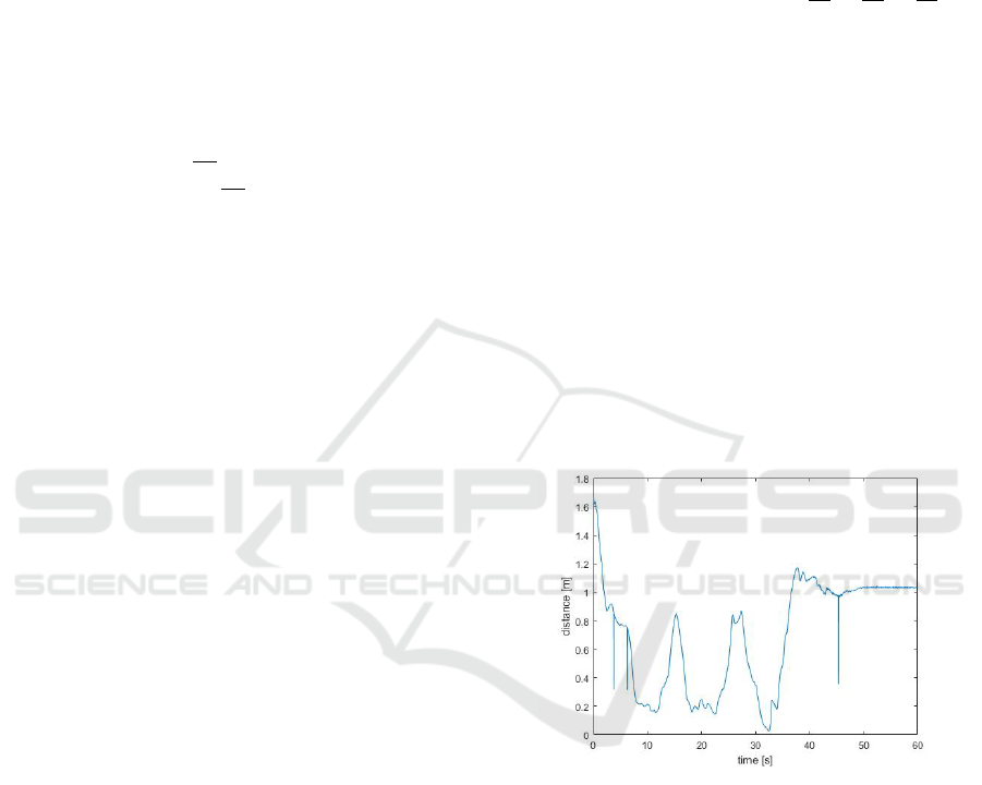
Figure 4: Result of the GMR retrival process.
Figure 4 reports the desired force profile generated
by the GMR (14),(15), which has an average around
−7N but with a significant variance due to the large
variability of the force exerted by the human operator
in the different polishing trials despite his/her skill.
4.2 Motion Trajectory Planning
In order to execute the 8-shaped figure described in
Section 2, the end-effector path has been defined ac-
cording to a Lissajous figure, which is a curve lying
Safe Robotized Polishing of Plastic Optical Fibers for Plasmonic Sensors
365
on a plane with parametric equation
x(t) = A
x
sin(ω
x
t + φ)
y(t) = A
y
sin(ω
y
t + φ)
t ∈ [0,2π] (19)
The shape of the curve is highly sensitive to the ra-
tio ω
x
/ω
y
. In particular, the Lissajous figure that best
suits the polishing task considered in this work is the
one obtained with ω
x
/ω
y
= 1/2 that corresponds to a
8-shaped path. To allow the robot end effector follow
the path described by the previous parametric equa-
tions, the desired end-effector position with respect to
a frame f centered in the center of the Lissajous figure
has to follow the path primitive
p
f
d
(s) =
A
x
sin(ω
x
2πk
L
s + π/2)
A
y
sin(ω
y
2πk
L
s)
0
s ∈ [0,L] , (20)
where L is the total path length (k times the length
of a single Lissajous figure, being k the lap num-
ber). Denoting with c
b
the position of the origin of
the Lissajous figure and with R
b
f
the rotation matrix
representing the orientation of the Lissajous frame f
with respect to the robot base frame, the end-effector
planned position with respect to robot base frame is
p
b
d
(s) = c
b
+ R
b
f
p
f
d
(s).
To obtain a desired end-effector position trajectory, a
time law linked to the path described by the Lissajous
figure is necessary. This can be accomplished by us-
ing a fifth-order polynomial with zero initial and final
velocity and acceleration.
Finally, the desired orientation trajectory has to
be specified, representing the end-effector orientation
with the XYZ set of Euler angles. By making sure
that at the beginning of the task the approach axis of
the end-effector frame is orthogonal to the table, the
desired orientation is set constant, i.e.,
φ
d
(t) = φ
e
(0) = φ
0
.
Moreover, in order to avoid the representation singu-
larity (the pitch angle equal to π/2), the end-effector
frame has been rotated of 180deg about the y axis
of the nominal end-effector frame so as to align the
end-effector frame with the robot base frame, namely
φ = 0. Eventually, the desired end-effector pose used
in the control law (5) is
x
d
(t) =
p
b
d
(s(t))
φ
0
, ˙x
d
(t) =
˙p
b
d
(s(t))
0
. (21)
5 EXPERIMENTAL VALIDATION
This section discusses the results obtained with the
control law described in Section 3.3 in terms of per-
formance of the robot and quality of the SPR-POF
sensor obtained at the end of the polishing.
5.1 Testing of the Robot Controller
The following parameters have been selected for the
control law described in Section 3.3
K
p
= diag{2000, 2000, 650, 140, 140, 140}
K
p
f
= diag{0, 0, 0.5, 0, 0, 0}
K
d
= diag{100, 100, 650,
√
50,
√
50,
√
50}
K
i
f
= diag{0, 0, 1, 0, 0}, K
el
= 5.5I
The proportional gain K
p
along x and y directions has
been chosen high enough to obtain a tracking error in
the order of 1 cm, while along the z direction it has
been chosen lower because along that direction the
force control action should predominate. The damp-
ing gain K
d
has been chosen so as to obtain a well-
damped behaviour along all directions. The propor-
tional K
p
f
and integral K
i
f
gains of the force con-
troller have been tuned based on a linearized model
of the system obtained considering an estimated con-
tact stiffness of about 2600N/m. Finally, the elastic
gain K
el
has been set as a trade off between the sensi-
tivity to the virtual repulsive wrench f
r
in (6) and the
elastic torque that drives the elbow point towards the
equilibrium configuration q
HE
in (8).
Figure 5: Minimum distance d during the experiment.
During the experiment a human operator has been
trained to enter the robot workspace while the polish-
ing task was being executed. The minimal distance d
between the human operator and the robot elbow is re-
ported in Fig. 5. Some spikes can be observed in the
figure due to an occasionally wrong tracking of the
skeleton by the Primesense algorithm. Nevertheless,
their duration is negligible and they are filtered out by
the torque controller, hence no corrections have been
made.
Joint torque commands computed by the control
algorithm in (4) allow the manipulator end-effector
follow the Lissajous figure as reported in Fig. 6. Po-
sition and orientation errors are shown in Fig. 7.
During the polishing, the force f
e
generated by the
ICINCO 2022 - 19th International Conference on Informatics in Control, Automation and Robotics
366
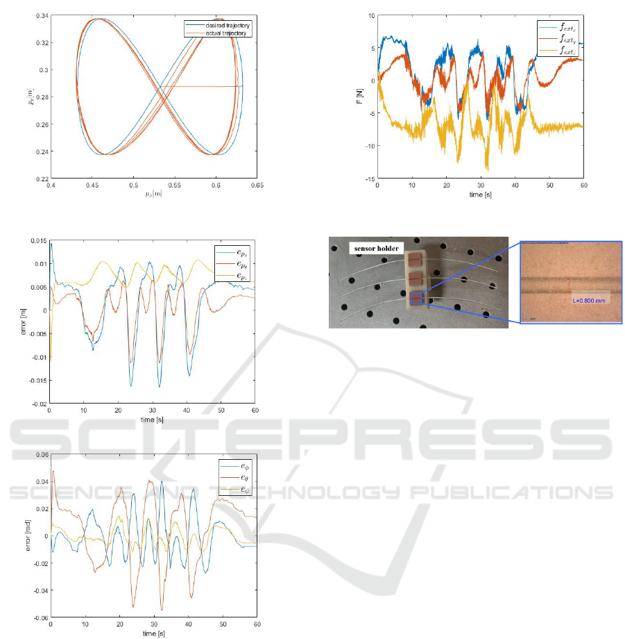
Figure 6: Desired and actual trajectories.
(a) Position tracking error.
(b) Orientation tracking error.
Figure 7: Position and orientation tracking errors.
contact between the fiber and the sandpaper on the ta-
ble is shown in Fig. 8. The x and y components are
due to the friction necessary to carry out the polish-
ing task successfully, hence they should not be coun-
teracted, that is why proportional and integral gains
along these directions are zero. The contact force
has been estimated from joint torques and a dynamic
model of the robot, according to the algorithm in (Ma-
grini et al., 2014).
Figure 8: Force profile during motion.
Figure 9: Top view of three POF sensor platforms at the
end of the polishing task. The digital microscope view on
the right shows the obtained length of the D-shaped fiber.
5.2 Sensor Production
Figure 9 shows the designed sensor holder, together
with a view of the polished region, for one of the
three sensors through a digital microscope. The D-
shaped POF width of about 0.8mm has been ob-
tained through the automatic polishing process after
one minute. It is worth emphasizing that the imple-
mented automated procedure leads to noticeable time-
saving. A reduction of about 70% can be achieved
with respect to the handmade one. Note that the use
of a robot for performing the polishing process allows
to accurately control the depth of the D-shaped POF
area and its roughness, by acting on the desired con-
tact force and the speed of the motion trajectory. The
depth parameter is particularly relevant for the sen-
sor performance as it affects the quality factor of the
plasmonic resonance (Gasior et al., 2014). After the
automatic polishing process, a gold sputtering process
has been used to realize the SPR-POF sensor.
5.3 Sensor Testing
Figure 10 reports the SPR transmission spectra ob-
tained experimentally, normalized to the spectrum
achieved with air as the surrounding medium, for sev-
eral water-glycerin solutions with a refractive index
ranging from 1.332 to 1.371. In particular, these re-
sults have been obtained exploiting a sensor configu-
ration without a buffer layer. So, after the automatic
Safe Robotized Polishing of Plastic Optical Fibers for Plasmonic Sensors
367
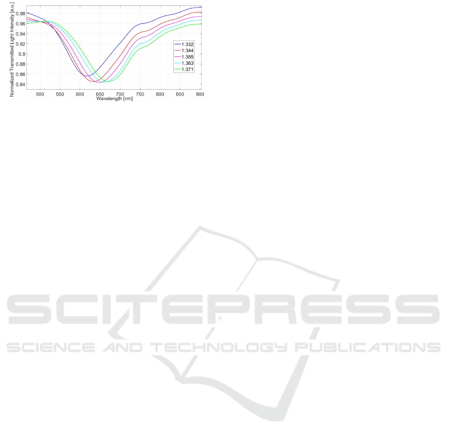
Figure 10: SPR spectra obtained by a D-shaped POF sen-
sor without the buffer layer (with a gold nanofilm on the
core of POF, directly) at different water-glycerin solutions
in contact with the gold nanofilm.
polishing process here proposed, only a gold sputter-
ing has been used to carry out the SPR-D-shaped POF
sensor. We have characterized the SPR-POF sensor
configuration without the buffer layer to better test the
automatic polishing process here proposed. With re-
spect to the SPR curves reported in (Cennamo et al.,
2011) in the same configuration, the SPR curves here
obtained present better performances in terms of full
width at half maximum of the SPR curve, due to the
automatic polishing process here proposed.
6 CONCLUSIONS
The experimental results presented in this paper
demonstrate the feasibility of the proposed approach
for automatic production of a SPR-POF sensor based
on the human-robot collaboration paradigm. The
robotized polishing phase results into a duration 70%
shorter than the current handmade process. The qual-
ity of the polishing process is at least comparable to
the handmade one as demonstrated by the SPR-POF
sensor tests. A characterization of the actual rough-
ness will be carried out by resorting to Atomic force
microscope measurements. This will allow to opti-
mize the process parameters. Moreover, the possi-
bility to establish the contact force so as to obtain a
given D-shaped depth with the aim to optimize the
plasmonic resonant quality factor will be investigated.
ACKNOWLEDGEMENTS
This work was supported by the VALERE program of
the University of Campania, CAMPANIA project.
REFERENCES
Calinon, S. (2018). Learning from Demonstration (Pro-
gramming by Demonstration), pages 1–8. Springer
Berlin Heidelberg, Berlin, Heidelberg.
Cennamo, N., Massarotti, D., Conte, L., and Zeni, L.
(2011). Low cost sensors based on spr in a plastic
optical fiber for biosensor implementation. Sensors
(Basel), 11(12):11752–11760.
Cennamo, N., Pesavento, M., and Zeni, L. (2021). A re-
view on simple and highly sensitive plastic optical
fiber probes for bio-chemical sensing. Sens. and Act.
B: Chemical, 331:129393.
Cohn, D., Ghahramani, Z., and Jordan, M. (1996). Active
learning with statistical models. J. Art. Intell. Res.,
4:129–145.
Dempster, A., Laird, N., and Rubin, D. (1977). Maxi-
mum likelihood from incomplete data via the em al-
gorithm. J. Royal Statist. Soc.: Series B (Methodolog-
ical), 29(1):1–38.
Flacco, F., Kroger, T., Luca, A. D., and Khatib, O. (2012). A
depth space approach to human-robot collision avoid-
ance. In 2012 IEEE Int. Conf. on Rob. and Aut. IEEE.
Gasior, K., Martynkien, T., and Urbanczyk, W. (2014).
Effect of constructional parameters on the perfor-
mance of a surface plasmon resonance sensor based
on a multimode polymer optical fiber. Appl. Opt.,
53(35):8167–8174.
Haddadin, S., Albu-Schaffer, A., Frommberger, M., Ross-
mann, J., and Hirzinger, G. (2009). The dlr crash
report: towards a standard crash-testing protocol for
robot safety - part II: Discussions. In 2009 IEEE Int.
Conf. on Rob. and Aut., pages 280–287. IEEE.
Khatib, O. (1987). A unified approach for motion and force
control of robot manipulators: The operational space
formulation. IEEE J. Rob. and Aut., 3(1):43–53.
Magrini, E., Flacco, F., and De Luca, A. (2014). Estimation
of contact forces using a virtual force sensor. In 2014
IEEE/RSJ Int. Conf. on Intell. Rob. and Syst., pages
2126–2133.
Natale, C. (2019). Physical Human-Robot Interaction,
pages 1–9. Springer London, London.
PrimeSense (2011). PrimeSense NITE Algorithms
1.5. https://www.yumpu.com/en/document/view/
11580035/primesense-nite-algorithms-15-openni.
Accessed on December 2021.
Schindlbeck, C. and Haddadin, S. (2015). Unified passivity-
based cartesian force/impedance control for rigid and
flexible joint robots via task-energy tanks. In 2015
IEEE Int. Conf. on Rob. and Aut. (ICRA), pages 440–
447.
Schwarz, G. (1978). Estimating the dimension of a model.
Annals of Statistics, 6(2):461–464.
Siciliano, B., Sciavicco, L., Villani, L., and Oriolo, G.
(2009). Robotics – Modelling, Planning and Control.
Springer.
Villani, L. (2020). Hybrid Force and Position Control,
pages 1–6. Springer Berlin Heidelberg, Berlin, Hei-
delberg.
ICINCO 2022 - 19th International Conference on Informatics in Control, Automation and Robotics
368
