
Simulation Driven Development Process Utilizing Carla Simulator
for Autonomous Vehicles
Minseok Won
1,2 a
and Shiho Kim
2b
1
System Test, Verification & Validation, HL Klemove, Incheon, 22011, Korea, Republic of
2
Seamless Transportation Lab., School of Integrated Technology, Yonsei University, Incheon, 21983, Korea, Republic of
Keywords: Simulation Driven Development Process, Verification and/or Validation, Autonomous Vehicles, EuroNCAP,
RSS.
Abstract: We present a new approach to design the system of autonomous vehicles based on practical test scenarios in
simulation. As the level of driving automation functions advances, various events and problems have occurred
in many unexpected or unseen situations, so the design of autonomous driving systems is required to be more
robust and sufficiently practical. We propose a Simulation Driven Development Process (SDDP) based on
practical test scenarios in a simulation environment. We described the Euro NCAP test scenarios and harsh
conditions using the ASAM OpenSCENARIO format and implemented them using the Carla simulator. We
can verify how realistic and functional the system requirements are through the simulation results. It is also
possible to derive numerical values optimized for Advanced Driver Assistance System (ADAS) function
safety from the simulation results, and we can get the requirements robust and improve ADAS performance
by applying them to V-model. We created the Euro NCAP AEB-VRU test scenario to design an effective
AEB function. We used RoadRunner to build the test road and used ScenarioRunner to render the test scenario
written by ASAM OpenSCENARIO format according to Euro NCAP test requirement. The result of AEB-
VRU has been investigated under normal conditions and harsh environments as well. This work shows that
we can extend the safety of the AEB function by changing the vehicle speed according to situation perception,
which indicates the possibility of utilization of a simulator for autonomous vehicle system design.
1 INTRODUCTION
The automotive industry has changed over the past
few years. With the leadership of the government,
industrial institutions including automakers, related
companies, research institutes, and universities have
focused their research on electric and hydrogen
vehicles from internal combustion engine vehicles,
and they are striving to secure a higher level of
autonomous driving technology. Accordingly, the
complexity of vehicle development is increasing, its
requirements are frequently changed, and the cycle of
development is getting faster. Simulation is being
utilized throughout the V-Model process from the
design stage of the vehicle to development and
validation in response to these changes.
Driving simulations allow us to verify various
scenarios iteratively so that we can travel “billions of
a
https://orcid.org/0000-0002-1077-4195
b
https://orcid.org/0000-0001-9935-1721
miles”, enabling difficult tests in the real world, and
making it possible to diagnose and verify real-world
problems before the actual implementation of
autonomous functions. A formal methods approach
using SCENIC language enables scenario-based test
generation for autonomous vehicles in simulation
(Fremont, et. al., 2020). A naturalistic and adversarial
driving environment by training the background
vehicles to learn when to execute what adversarial
maneuver can significantly reduce the required test
miles without loss of evaluation unbiasedness (Feng,
et. al., 2021).
Our motivation is to plan practical and verified
test cases through the test scenarios proposed by Euro
NCAP, and to build a simulation environment that
guarantees freedom of implementation by utilizing
Carla Simulator, an open-source autonomous driving
simulator. In addition to verifying the system
202
Won, M. and Kim, S.
Simulation Driven Development Process Utilizing Carla Simulator for Autonomous Vehicles.
DOI: 10.5220/0011139300003274
In Proceedings of the 12th International Conference on Simulation and Modeling Methodologies, Technologies and Applications (SIMULTECH 2022), pages 202-209
ISBN: 978-989-758-578-4; ISSN: 2184-2841
Copyright
c
2022 by SCITEPRESS – Science and Technology Publications, Lda. All rights reserved

document through basic test scenarios, the limitations
of functions are verified at the design stage, and
requirements for optimizing performance for sudden
and unpredictable driving situations are derived by
adding a harsh environment. Finally, the performance
is evaluated through simulation evaluation of the
Autonomous Emergency Braking (AEB) function,
which is one of the key Advanced Driver Assistance
System (ADAS) functions.
The remainder of this paper is structured as
follows: In Section 2, we provide the methodology of
the development process of vehicle software. Section
3 provides the states of the art for driving simulation
and responsibility-sensitive safety (RSS). The
concept of our approach and its implementation are
presented in Section 4 before the experimental results
and evaluation in Section 5. Finally, we conclude this
paper in Section 6.
2 METHODOLOGY
2.1 V-model
The demand for autonomous driving functions in the
automobile industry continues to expand. As the
number of sensors increases, so does the number of
ECUs in the vehicle. The increase of ECUs and
autonomous driving functions makes the related
software more complex and scalable. Therefore,
many countries and automakers strive to minimize the
risk of failure by complying with international
standards such as ISO26262 and Automotive
Software Process Improvement and Capability
Determination (ASPICE) for developing autonomous
driving software. And they follow the typical
development process, V-model (Rook, et. al., 1986).
The process varies from manufacturer to
manufacturer in detail, but it is largely divided into
two stages. One consists of requirements analysis,
functional design, and development. The other
proceeds with verification and validation of these. V-
model is an extension of the waterfall methodology
and it is aligned with the ASPICE standard. Each
development step is clearly defined and separated in
the model. V-Model emphasizes testing, particularly
the need for early test planning. This reflects the
Broken Window Theory (Wilson, et. al., 1982). If the
early stages of development are verified and
improved, the overall costs are reduced and the
quality is enhanced. However, sometimes the
requirements may not contain implementation details
in many cases. Therefore, the system’s practical
operation will be required based on real-world
scenarios. The V-model is clear and easy to track
current development status and before and after. If
only the requirements are established in the initial
stage, the overall process runs efficiently.
We propose a Simulation Driven Development
Process (SDDP) using simulation from the initial
stage of the V-model to refine requirements based on
feasible scenarios. The use of our proposed system
from the requirement analysis stage in the V-model is
beyond the limited module unit verification such as
the existing Model in the Loop (MiL), it is not only
essential for functional design based on basic vehicle
test scenarios, but also more practical by simulating
unexpected situations or harsh environment where
autonomous driving is difficult. It will enable realistic
and practical design and development of ADAS by
utilizing simulators from the first step of the V-model.
2.2 Development Methodology
In the past, automotive software development was
based on a waterfall method that went through the
process of analyzing requirements, designing,
implementing, and testing in turn, but the cycle of
software development is getting faster and the
requirements are changed frequently (Balaji, et. al.,
2012). To actively respond to these changes, different
development methods are used.
A goal-driven requirements engineering method
is the Knowledge Acquisition in Automated
Specification (KAOS) model approach in which the
main goal is decomposed into sub-goals and then
refine the subgoals again until reaching explicit,
unambiguous requirements (Fatima, et. al., 2015).
The method proceeds by discovering the stakeholders’
goals and by using these goals to unveil and motivate
system requirements. Both bottom-up and top-down
approaches are typically used to identify the
stakeholders’ goals. Goals are hence refined from
more general strategic goals to lower-level
operational goals. All system requirements are
identified and introduced in the model to meet some
operational goals. It is designed using the Objective
tool to find the reconciling requirements (Singh, et.
al., 2017).
A graph-based development has the advantages of
modularity and reusability of sub-scenarios. The
method enhances comprehensibility for other
engineers. This approach makes the scenario creation
to be easily generated and enables the utilization of
scenarios within development and testing steps
(Schütt, et. al., 2020).
A situation-based method especially focuses on
road intersections where the highest accidents occur.
Simulation Driven Development Process Utilizing Carla Simulator for Autonomous Vehicles
203

The development environments are based on an
ontology of all possible situations at the intersection.
Derivative of the ontology developed automatically
and randomly creates test suites according to a
situation coverage criterion (S. Lee, et. al., 2021). The
situation-based method finds the weaknesses of the
autonomous driving algorithms, especially in edge
cases which are combinations of harsh environments
and intersection road conditions (Tahir, et. al., 2021).
There is a survey study of various methodologies
for developing autonomous vehicles to establish an
integrated method for testing autonomous driving at
different stages of development. Development
methods are used in appropriate situations according
to their characteristics (Huang, et. al., 2016).
However, most development methods focus on
how efficiently the system requirements are reflected
in the software. Our proposed development process is
a simulation-driven development. The purpose of our
method is to verify requirements from the design
stage to validate the performance using reusable and
practical test scenarios in a simulation environment.
3 STATE OF THE ART
3.1 Driving Simulation
A driving simulator facilitates the development and
testing of autonomous driving systems. It provides
physics models for automotive, and robotics and
allows them to build testing environment systems.
Unity is available free for non-commercial versions.
Unity is a cross-platform game engine developed by
Unity Technologies. The unity engine can be used to
create three-dimensional (3D) and two-dimensional
(2D) games, as well as interactive simulation and
other experiences. However, the usage of platform
and asset re-source can be paid access only (Juliani,
et. al., 2018).
SCENIC is a probabilistic language to generate
realistic scenes automatically for autonomous vehicle
learning or testing in a virtual environment. The
system based on machine learning uses a modeling
language as an input source to build simulation assets
such as background, vehicles, and any traffic
scenarios as well (Fremont, et. al., 2019).
Carla is an open-source simulator with the special
purpose of autonomous driving. It provides flexible
APIs and high-quality assets. Its physics models and
rendering are performed by the Unreal Engine (Oliver,
et. al., 2012). Carla is designed as a client-server
system. Multiple clients can connect to the server
simultaneously. The server builds the driving test
world. The client provides interfaces between users
and the virtual world by controlling the ego actors.
Because of this, multiple developers can access the
Carla at the same time, and enable support training,
prototyping, and validation of autonomous driving
models, including both perception and control while
experiencing realistic driving in the simulation
environment (Dosovitskiy, et. al., 2017).
3.2 Responsibility-Sensitive Safety
Responsibility-Sensitive Safety (RSS) is a model
proposed by Intel and Mobileye to ensure the safety
of autonomous vehicles (Gassmann, et. al., 2019). It
was presented to use the autonomous vehicle as a
basis for determining who is responsible in the event
of a traffic accident. NVIDIA also has a calculated
defensive driving policy, Safety Force Field (SFF), to
prevent collisions with autonomous vehicles. They
have similarities in focusing on the protection of the
autonomous vehicle from collision. The
mathematical model provides safety functions for
digitization of these implicit driving rules as follows.
Ego vehicle does not hit the car front. RSS
calculates the safe longitudinal distance.
Ego vehicle does not cut into the car in the next
lane. RSS calculates the safe lateral distance.
Ego vehicle has right of way according to RSS
situation perception
Ego vehicle drives slowly with RSS limited
visibility
If an ego vehicle can avoid a crash without
causing another one, change the lane.
Although RSS has a function similar to the ADAS
functions such as Adaptive Cruise Control (ACC),
and AEB, it delegates its judgment to the situation
perception without presenting a mathematical model
except for calculating longitudinal and lateral
distance. Functionally, ADAS assumes that the
driving speed is maintained when calculating the
distance during the reaction time. On the other hand,
since RSS assumes that the speed of the front vehicle
changes at the maximum deceleration and the speed
of the rear vehicle changes at the maximum
acceleration during the reaction time, a relatively long
safety distance is calculated with low-speed. As a
result, RSS has a longer distance than necessary in the
low-speed section. If the safe distance is excessively
secured, the traffic flow may be slower and it causes
inefficient vehicle flow. Therefore, RSS needs to
percept the situation for improving its performance
and it is possible to be trained and validated under the
simulation environment.
SIMULTECH 2022 - 12th International Conference on Simulation and Modeling Methodologies, Technologies and Applications
204
4 CONCEPTIONS OF THE
SIMULATION ENVIRONMENT
4.1 The Environment of a
Simulation-driven Development in
the V-model
The V-model process has the advantage that product
development proceeds properly as the activity of each
stage is clear and step-by-step verification is carried
out. However, it is not easy to verify the upper design
level in this waterfall method. Therefore, we propose
a process that applies a simulation-driven
development to the V-model so that verification of
each stage is continuously performed in one
simulation environment as shown in Figure 1.
At the design level, the requirements can be
verified according to the simulation results reflecting
Euro NCAP scenarios, and realistic numerical values
are applied to the documents. The improved
requirements lead to detailed development
requirements, which ultimately lead to optimized
product performance.
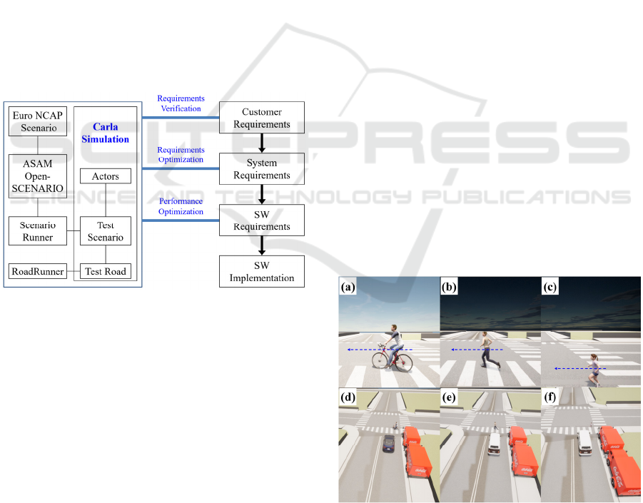
Figure 1: The proposed process of SW requirements
verification utilizing the Carla simulation environment.
4.2 Writing Test Scenario using ASAM
OpenSCENARIO Format
The simulation environment for the verification and
validation in the V-Model process requires flexibility
and compatibility. ASAM OpenSCENARIO defines
a standard format to describe driving test situations
including assets, scenarios, and traffic conditions.
Other information, such as the explanation of the ego
vehicle, pedestrian trajectory, and weather condition,
is included as well. The standard format is useful to
synchronize the movements of multiple agents like
vehicles, bikes, pedestrians, and other traffic
participants. All contents can be categorized and
parameterized. Additionally, the test scenario
supports parameterization, which allows test
automation without creating a large size of scenario
sequences. They are hierarchized and structured with
an XML file format as the standard. It is easily
editable and interacts with other formats.
This is a simple example of writing generation of
actors and positions as follows:
<Vehicle name="vehicle.veh03"
Category="car">
<Pedestrian model="walker.ped01"
Category="pedestrian">
<WorldPosition x="150" y="55" z="0"
h="0"/>
<Maneuver name="PedestrianCrossing
Maneuver">
<Event name="PedestrianStarts
Walking" priority="overwrite">
<Action name="Starts Walking">
To create vehicles and pedestrians in a scenario,
write vehicle and pedestrian names in each category,
respectively, and input the x, y, z, and heading angles
of the test world. Event triggers and actions can make
pedestrians walk. In this way, we can take the
readability of the test scenarios and the ease of
modification of them.
We wrote the start point, endpoint, and speed of
the ego vehicle through ASAM OpenSCENARIO
Format. In addition, by writing the pedestrian's start
point, endpoint, speed, and event trigger, a scenario
was created in which a pedestrian crosses the road
when an event condition is triggered while the ego
vehicle is driving. The format is functionalized in the
simulation environments through ScenarioRunner in
python format. Figure 2 shows the generation of
AEB-VRU test scenarios using the formats.
Figure 2: Euro NCAP AEB-VRU test scenario: The front
view of Car-to-Bicyclist Nearside Adult (CBNA, a); of Car-
to-Pedestrian Nearside Adult (CPNA, b), and Car-to-
Pedestrian Nearside Child (CPNC, c); The bird view of
CPNA (d); of CPNA (e), and CPNC (f).
Simulation Driven Development Process Utilizing Carla Simulator for Autonomous Vehicles
205
4.3 A Modeling of Actors and Harsh
Environments
The Carla simulator allows us to build a virtual
environment with realistic configurations to validate
the practical test scenarios. We can utilize various
vehicles, pedestrians, sensors, and physical
environment models provided by Unreal Engine to
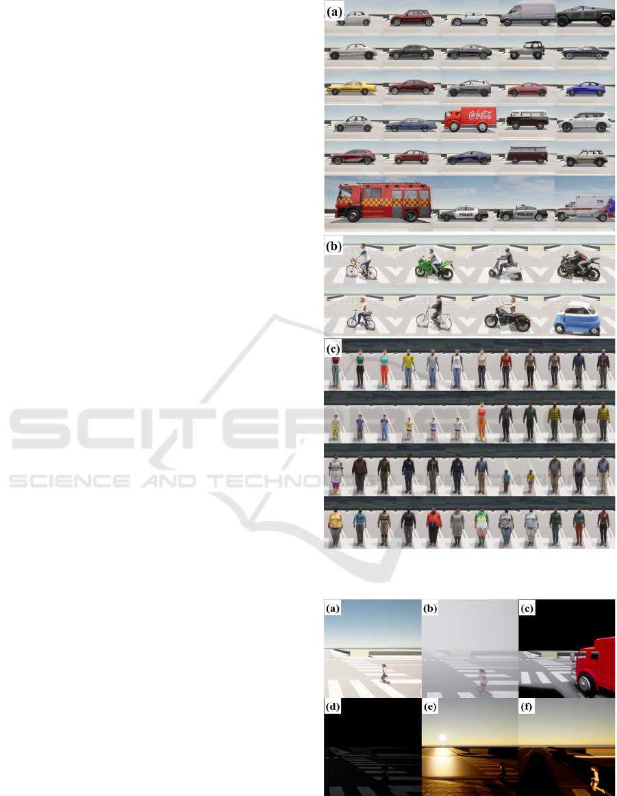
implement test scenarios in the simulation. Figure
3(a) shows vehicles that can be used in the simulation
environment. Various types of vehicles can
participate in the test environment through the
simulator. Each vehicle can apply different vehicle
kinematics and/or control dynamics parameters such
as size, weight, gear, toque, wheels, and so on. Even
the sensor models are equipped differently, and the
mounting position and performance of the sensor can
be implemented in a variety of ways as a real vehicle.
Therefore, automakers or parts suppliers can verify
and optimize the ADAS functions of any vehicle for
functional requirements.
Euro NCAP emphasizes safety for vulnerable
road users (VRU) such as pedestrians and cyclists and
especially provides AEB-VRU test protocols for the
AEB function of ADAS. The real test is assessed
using controllable balloon dolls in the shape of
pedestrians and bicycles. Pedestrians are divided into
an adult and a child and are designated with black
shirts and blue pants. In addition to the VRU
proposed by Euro NCAP, we have created a variety
of pedestrians as shown in Figure 3(c). By
differentiating gender, race, and/or hairstyle, ADAS
functional validation for pedestrians is more practical
in the simulation environment. Cyclists also can be
changed in various ways, rather than one specified
size and shape. As shown in Figure 3(b), the models
such as bicycles, motor-bike, and small electric
vehicles can be used, so it is possible to cover the area
where the test cannot be confirmed in actual driving.
Driving simulation has the advantage of being
able to reproduce and validate test scenarios that
require a long wait in a real vehicle at any time and
place. This allows us to iteratively validate our test
scenarios under different time and weather conditions.
Through the OpenSCENARIO format, the time and
weather conditions of the test environment can be
written simply, and this is reflected in the Carla
simulation as a change in the physical environment of
the Unreal Engine. These changed time and weather
conditions enable validation of ADAS functions in
adverse environments, such as at night, in fog, in
heavy rain, and in backlight conditions. Figure 4
shows the test scenarios for different times and
environmental conditions.
Figure 3: The modeling of actors utilized in the test scenario:
(a) Vehicles; (b) Road users two-wheeled; (c) Pedestrians.
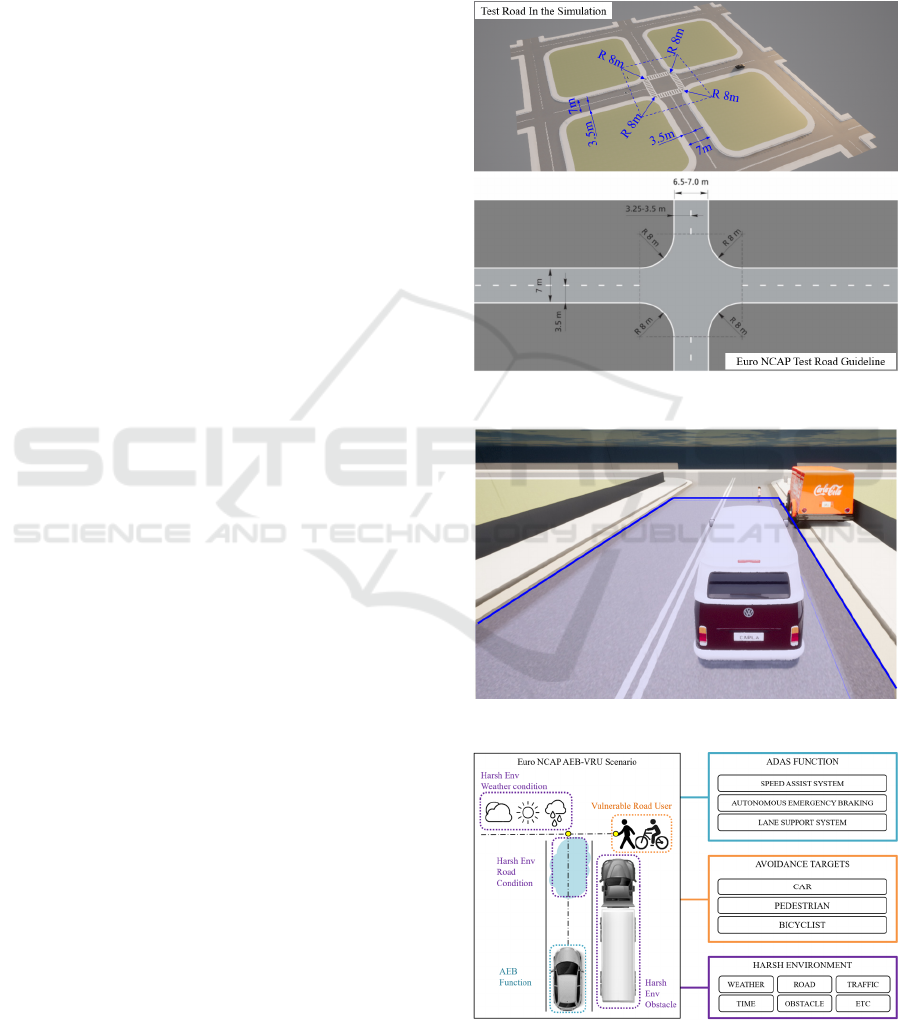
Figure 4: Screenshots of the harsh environmental condition:
(a) Day; (b) Foggy; (c) Light turned on darkness; (d) No
light in darkness; (e) Sunset; (f) Sunrise.
SIMULTECH 2022 - 12th International Conference on Simulation and Modeling Methodologies, Technologies and Applications
206
5 SIMULATION AND
EVALUATION
5.1 Description of the AEB-VRU Test
Scenario and Modeling
We aim to implement the AEB-VRU test scenario
proposed by Euro NCAP in a virtual environment to
evaluate the AEB function and derive improved
system requirements to improve AEB-VRU safety
due to performance degradation in Harsh
Environment situations.
Since the ego vehicle’s speed is constant in this
scenario, A two-lane round-trip road model is used to
represent the vehicle dynamics. Test roads are created
according to the guidelines of Euro NCAP with a
constant width of 3.5 m in the environment. The
sensor model consists of a front radar, which
measures the distance to the front target in an angular
range of ±15 °, and a camera, which detects the object
to the front from the Carla sensor model. The AEB
function is a key ADAS function for braking the ego
vehicle within the time to collision (TTC) limit. The
TTC requirements for the AEB function are
dependent on a car manufacturer but it usually has a
variable range from 1.0 to 2.5 seconds. We fixed the
TTC of the AEB function to 1.8 seconds for the test
environment in this work.
We prepare the two types of variables. The first
variable is visibility, with or not obstacles on the road.
The second variable is road condition, the normal
road, and wet road. The obstacles blocking the view
and the wet road cause lower friction. The friction
between the tires of the test vehicle and the road
determines the minimum stopping distance. The
coefficients of friction are about 0.7 for dry roads and
0.4 for wet roads (Jin, et. al., 2014). In the simulation,
we assigned a braking zone and friction triggers.
Friction triggers let users define different friction of
the vehicles' wheels when being inside those types of
triggers. When entering the zone, the coefficient of
friction of the road surface was set to 60% (i.e. ≈
100×0.4/0.7) of a dry road surface, which could easily
drop braking performance on the slippery road. The
ego vehicle runs at a constant speed and performs
simulations from 5kph to 45kph in 0.5kph
increments. When the ego vehicle approaches a
distance of about 30 meters from the pedestrian, the
pedestrian begins to cross the road. The pedestrian
has a constant speed according to the vehicle's speed
to meet TTC requirements.
Figure 5 shows the real test road and the
simulation road. The 3.5m lane width and 8m radius
of curvature required by the Euro NCAP test were
applied. The slippery road of the simulation test
environment is visualized in Figure 6. We can get
lower friction by changing the value of the friction
coefficient in simulation.
Figure 7 shows the overview of the AEB-VRU
scenario. Vehicles, pedestrians, bikes, or other actors
are generated on the road and harsh conditions such
as bad weather, road friction, traffic situation, night,
and obstacles can be added.
Figure 5: Overview of the track for test drive simulation.
Figure 6: Lower friction visualized on the slippery road.
Figure 7: Overview of the Proposed simulation for the
AEB-VRU scenario.
Simulation Driven Development Process Utilizing Carla Simulator for Autonomous Vehicles
207
5.2 Simulation Results and Evaluation
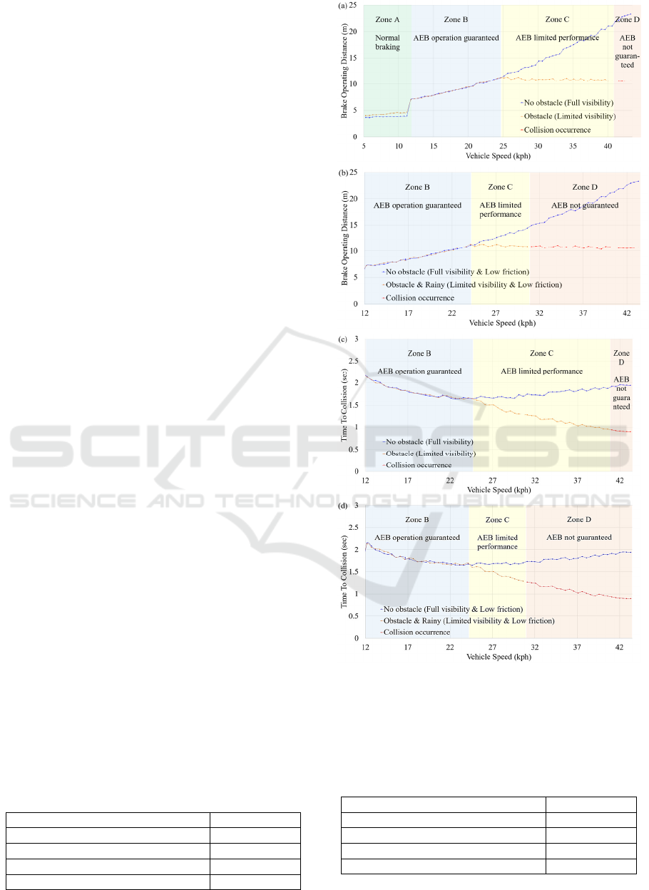
The results show that there is a 4-zone in AEB
performance domains shown in Figure 8. Zone A is
where AEB is not operating due to low vehicle speed.
Zone B is where the AEB function is operating
properly to meet the TTC of 1.8 sec. In full visibility
of the target ahead, the function acts to brake
perfectly and there were no crashes within the speed
range. For harsh conditions, we added an obstacle of
a parked car, to occlude the visibility of the ego
vehicle. Even though the field of vision to the target
is limited by obstacles, the almost same level
performs. However, at the speed above that, brake
operation distance does not increase until collision
occurrence. Zone C is where the AEB function has
limited performance. The function is not guaranteed.
Zone D is where the occurrence of a collision is
satisfied.
Figure 8(b) shows the AEB performance by
adding a harsher environment, and wet conditions.
When the friction is lower, the brake distance
becomes longer. However, the performance with no
obstacle leads to no crashes in the test speed range.
On the other hand, if the visibility is limited by
obstacles, the collision occurs at lower speed
conditions. It shows that the Zone C area is reduced
while the Zone D area is expanded. Therefore, it can
be derived that the presence of obstacles causes
limitations in AEB operation. In addition, the lower
friction affects the performance limit to avoid
collision significantly.
TTC decreases if obstacles block the detection of
targets. The performance degradation occurs because
targets can’t be tracked and suddenly appear as shown
in Figure 8(c). The result with lower friction is in
Figure 8(d). Therefore, if AV has full visibility, the
AEB function performs properly despite low friction.
Table 1 lists the RMSE of TTC. The performance
is greatly affected by the presence of occluding
obstacles. 0.498/ 0.190 sec is with/without occluding
obstacles, respectively. Lower friction gets the
performance limit lower. Table 2 shows the crash rate
as shown in Figure 8. No collisions occurred in two
cases; 1) No occluding obstacle on a dry road, and 2)
No obstacle under the wet road. However, collisions
occurred for 12.9% of test cases with obstacles on the
normal road, furthermore, the accident rate increased
to 35% of test cases on the wet road.
Table 1: RMSE of time to the collision of each condition.
Test Environment RMSE
No occluding obstacle on dry roa
d
0.190
No obstacle under Rain
y
0.192
Occluding Obstacles on dry roa
d
0.498
Occludin
g
Obstacle under Rain
y
0.502
Figure 8: Simulation results of the AEB-VRU test scenario:
Brake operation distance comparison between w/ and w/o
obstacle on the normal road (a), and for on the wet road (b);
TTC comparison between w/ and w/o obstacle on the
normal road (c), and on the wet road (d).
Table 2: Simulated AEB crash rate for test speed conditions
shown in Fig. 8.
Test Environment Rate
(
%
)
No occludin
g
obstacle on dr
y
roa
d
0
No obstacle under Rain
y
0
Occluding Obstacles on dry roa
d
12.5
Occluding Obstacle under Rain
y
35.0
SIMULTECH 2022 - 12th International Conference on Simulation and Modeling Methodologies, Technologies and Applications
208

6 CONCLUSION AND OUTLOOK
We proposed a simulation-driven development
utilizing the Carla simulator that verifies the design
and validates the performance. The proposed
methodology is to process V-model with a simulation
environment. To confirm and prove this process, we
built the simulation environment to execute the test
scenarios from Euro NCAP especially, AEB-VRU
and we added harsh environments such as obstacles
and rainy conditions. A harsh environment was
applied as a complex element in the simulation
results. Because changes in the driving environment
are not simply affected by one variable, but they are
affected by various environmental variables, not only
weather conditions but also road friction were
simulated in the system when applying the rainy
environment to the simulation. These simulation
environments allow us to recognize the driving
environment and iterate on how to react to the
perceived environment, thereby making requirements
robust and improving performance for autonomous
driving.
We found four domains of AEB performance
from the simulation results and derived the vehicle
speed value for AEB operation guaranteed and
limited speed value under the harsh environment we
set. By repeating these processes in the simulation
environment, key variables can be optimized from the
test result which makes the system requirements
robust. Our proposed process can be used for a variety
of purposes, such as not only for functional
requirements, but also for optimized sensor mounting,
practical test case development, and counterplan to
unexpected issues occurring in the real world.
ACKNOWLEDGMENTS
This work was supported by the Institute for
Information Communications Technology Planning
Evaluation (IITP) grant funded by the Ministry of
Science and ICT (MSIT, Korea, No.2021-0-01352,
Development of technology for validating auto-
nomous driving services in perspective of laws and
regulations).
REFERENCES
Balaji, Sundramoorthy, and M. Sundararajan Murugaiyan.
"Waterfall vs. V-Model vs. Agile: A comparative study
on SDLC." International Journal of Information
Technology and Business Management 2.1(2012):26-30.
Dosovitskiy, Alexey, et al. "CARLA: An open urban
driving simulator." Conference on robot learning.
PMLR, 2017.
Fatima, Mizbah. "KAOS: A Goal Oriented Requirement
Engineering Approach." International Journal for
Innovative Research in Science & Technology 1.10
(2015): 133-135.
Feng, Shuo, et al. "Intelligent driving intelligence test for
autonomous vehicles with naturalistic and adversarial
environment." Nature communications 12.1 (2021):1-14.
Fremont, Daniel J., et al. "Formal scenario-based testing of
autonomous vehicles: From simulation to the real
world." 2020 IEEE 23rd International Conference on
Intelligent Transportation Systems (ITSC). IEEE, 2020.
Fremont, Daniel J., et al. "Scenic: a language for scenario
specification and scene generation." Proceedings of the
40th ACM SIGPLAN Conference on Programming
Language Design and Implementation. 2019.
Gassmann, Bernd, et al. "Towards standardization of av
safety: C++ library for responsibility sensitive safety."
2019 IEEE Intelligent Vehicles Symposium (IV).
IEEE, 2019.
Huang, WuLing, et al. "Autonomous vehicles testing
methods review." 2016 IEEE 19th International
Conference on Intelligent Transportation Systems
(ITSC). IEEE, 2016.
Schütt, Barbara, et al. "SceML: A graphical modeling
framework for scenario-based testing of autonomous
vehicles." Proceedings of the 23rd ACM/IEEE
International Conf. on Model Driven Engineering
Languages and Systems. 2020.
Jin, Hui, and Min Zhou. "On the road friction recognition
based on the driving wheels deceleration." 2014 IEEE
Conference and Expo Transportation Electrification
Asia-Pacific (ITEC Asia-Pacific). IEEE, 2014.
Juliani, Arthur, et al. "Unity: A general platform for
intelligent agents." arXiv preprint arXiv:1809.02627
(2018).
Oliver, Paul. "Unreal engine 4 elemental." ACM
SIGGRAPH 2012 Computer Animation Festival. 2012.
86-86.
Rook, Paul. "Controlling software projects." Software
engineering journal 1.1 (1986): 7-16.
S. Lee, et al. “An open-world novelty generator for
authoring reinforcement learning environment of
standardized toolkits.” International Conf. on Multi-
disciplinary Trends in Artificial Intelligence 2021, (pp.
27-33). Springer, Cham.
Singh, Madhusudan, and Shiho Kim. "Reconcile security
requirements for intelligent vehicles." 17th
International Conference on Control, Automation and
Systems (ICCAS). IEEE, 2017.
Tahir, Zaid, and Rob Alexander. "Intersection focused
Situation Coverage-based Verification and Validation
Framework for Autonomous Vehicles Implemented in
CARLA." arXiv preprint arXiv:2112.14706 (2021).
Wilson, James Q., and George L. Kelling. "Broken
windows." Atlantic monthly 249.3 (1982): 29-38.
Simulation Driven Development Process Utilizing Carla Simulator for Autonomous Vehicles
209
