
A Novel Connection Mechanism for Dynamically Reconfigurable
Modular Robots
James White
a
, Mark A. Post
b
and Andy M. Tyrrell
c
Department of Electronic Engineering, The University of York, U.K.
Keywords:
Modular, Robotics, Reconfigurable.
Abstract:
This paper describes a novel hermaphroditic, single sided disconnect physical connector for heterogeneous
modular robots built using eight permanent magnets arranged in rotating pairs. The connector has 4 rotational
degrees of symmetry and incorporates power and data sharing. The connector has been designed as part of
a project creating 10 cm cubic heterogeneous modules but could be easily scaled to different sizes for other
applications. The paper begins with an introduction to connection mechanisms in modular robots, followed
by a detailed description of the design of the connector. A description of the simulation environment created
to test systems of interconnected modular robots is given, followed by the implementation and testing of the
connection system created.
1 INTRODUCTION
A modular robotic system consists of a set of inter-
connected robotic nodes, or modules, that together
form a larger robotic system. There are various clas-
sifications of modular robotic systems, described in
detail by (Brunete et al., 2017) and (Yim et al., 2007).
The system described in this paper conforms to the
categories of dynamically reconfigurable and hetero-
geneous. A dynamically reconfigurable system is one
that can reconfigure it’s structure during run-time to
cope with local failures (such as ejecting a broken
module from the system) or functionality changes
(such as reconfiguring for different locomotion strate-
gies or repositioning a sensor module for extended
field of view). A heterogeneous modular robotic sys-
tem is one in which the modules that make up the
system are not all identical. These modules can in-
terconnect to form a larger system through the use of
a standardised mechanical and electrical interface.
Communication between modules was identified
as a major barrier to better systems of modular robots.
For modules to cooperate effectively, there is a need
for both high throughput and low latency communi-
cation. The majority of modular robot systems to
date have used Infrared, UART, CAN bus or Infrared
a
https://orcid.org/0000-0002-7123-9348
b
https://orcid.org/0000-0002-1925-7039
c
https://orcid.org/0000-0002-8533-2404
diode pairs for their primary communication. While
these work well for propagating control commands
around a system, they do not work well for dynam-
ically reconfigurable systems with both low latency
and high throughput requirements. A network sys-
tem providing higher bandwidth and more resilient
communications for modular robots has been devel-
oped based on the IEEE 802.3 Ethernet standard for
the physical layer. A novel networking protocol to
handle data flow and topology discovery in the net-
work is being developed for reconfigurable modular
robotic systems. This research is focused around a
system where modules have a 100mm cubic structure,
constructed out of six submodular tiles. The submod-
ular tile design enables the modules themselves to
be modular and share common components in man-
ufacture. This accelerates development of special-
ized heterogeneous modules and reduces design and
manufacturing costs as well as facilitating investiga-
tions into hierarchical modularity. A dynamically re-
configurable modular system needs to be able to per-
form in-process physical reconfiguration. To facilitate
this, modules must have a robust electro-mechanical
connection mechanism that accommodates transfer of
mechanical forces, power and communication data.
The most fundamental design aspects of modular sys-
tem design are the use of common communication
and power transmission systems throughout these het-
erogeneous agents to allow them to create connect to-
gether for any configuration needed for a given task.
White, J., Post, M. and Tyrrell, A.
A Novel Connection Mechanism for Dynamically Reconfigurable Modular Robots.
DOI: 10.5220/0011141100003271
In Proceedings of the 19th International Conference on Informatics in Control, Automation and Robotics (ICINCO 2022), pages 385-394
ISBN: 978-989-758-585-2; ISSN: 2184-2809
Copyright
c
2022 by SCITEPRESS – Science and Technology Publications, Lda. All rights reserved
385

These systems must be resilient to faults and fail-
ures as well as providing high communication band-
width and power throughput to keep systems operat-
ing in harsh and challenging environments. Potential
applications of dynamically reconfigurable heteroge-
neous modular robots include, but are not limited to:
modular satellites; A modular satellite system would
be greatly beneficial to the space industry because if
there is a fault or upgrade needed, then a small, mod-
ule payload can be sent to the asset, which will then
autonomously reconfigure to accommodate it, rather
than requiring a whole new asset al.together to fulfill
requirements, reducing cost and extending in-service
life of satellites.
The research contributions of this paper are; a
novel interconnection and communications system
for reconfigurable modular robots from the physi-
cal layer up that is designed to allow modules in
a dynamically reconfigurable network to communi-
cate effectively, a novel rotating permanent magnet-
based physical connection mechanism for modular
robots that allows single sided disconnect and recon-
nect, a system of sharing data and power using the
permanent magnets as electrical conductors, and a
heterogeneous, dynamically reconfigurable modular
robotics platform that can demonstrate the effective-
ness of these novel systems and how they enable fur-
ther research to be carried out in the field of modular
robotics.
2 PREVIOUS WORKS
This section provides a brief review of the literature to
date regarding modular robotic systems. A review of
the research history of modular robots is provided at
first, followed by a quantitative review of communi-
cation systems used within modular robotic systems.
Finally a review of power distribution amongst nodes
in a modular robotic system is presented.
2.1 Modular Robots
Research into modular robotics systems was first con-
ducted by Fukuda et al.(Fukuda and Nakagawa, 1988)
in 1988 with the creation of CEBOT. Since then, more
than 60 modular robot systems of varying capabilities
have been developed for research purposes. Modular
robotics have been identified as potentially beneficial
to industries such as space(Yim et al., 2003), search
and rescue(Pfotzer et al., 2014) and other harsh en-
vironments where a system that can dynamically re-
configure to cope with partial failures or contain built
in redundancy mechanisms is desirable. There are a
number of detailed review papers published regard-
ing the field of modular robotics (Yim et al., 2007;
Moubarak and Ben-Tzvi, 2012; Brunete et al., 2017;
Ahmadzadeh et al., 2016; Feczko et al., 2015).
2.2 Communication in Modular Robots
Throughout the 30 year history of modular robotics
research, authors have chosen to adopt many different
communication standards for their platforms. As the
underlying embedded technologies have evolved, so
have the physical layers and protocols used. Figure
1 shows the usage of different communication stan-
dards across all the modular robotic systems reviewed
over time. The modular robotic platforms are tabu-
lated in Table 1. Thirteen individual protocols were
found to be used. It can be seen that Infrared (IR)
is the most widely used, with nearly a quarter of all
modular robots using the technology. IR is a wire-
less protocol which is easy to implement in embedded
systems, this is likely why it is the choice for many
system designers. It is good for modular robotics as
it does not require an electrical connection between
modules, making mechanical design easier, but with
the need for line-of-sight for communication to work
and bandwidth limitations, it is unsuitable for a ro-
bust system. CAN is the second most popular choice
for communications between modules. It was first
used by Yim et al. in the CKBot Platform(Yim et al.,
2007). CAN is a multi-drop bus based protocol which
was originally developed for communication between
processors in an automotive environment. Bluetooth
has been popular too as it is easy to implement due
to there being no need for electrical interface between
modules and that there are many bluetooth-to-serial
modules available commercially making electronics
implementation easy. Problems quickly arise with
bluetooth as the number of modules increase how-
ever, making it only suitable for small scale modular
systems. Bluetooth was implemented in the YaMoR
platform(Moeckel et al., 2006), with the authors not-
ing that is was primarily chosen for ease of imple-
mentation. To date only one modular robotic plat-
form has used Ethernet for communication between
modules. This was CoSMO platform by Liedke et
al.(Liedke et al., 2013). The authors cite the collision-
free, high-speed, hot-pluggable properties of Ether-
net influencing the decision to use it, along with the
ability to have arbitrary topologies and accumulating
bandwidth with the use of trunking of multiple packet
routes simultaneously.
ICINCO 2022 - 19th International Conference on Informatics in Control, Automation and Robotics
386

Year of System Publication
Number of Uses
0
5
10
15
20
25
30
35
40
45
50
55
60
65
1990 1995 2000 2005 2010 2015 2020
LIN Magnetic serial Ethernet RS232 COMBUS 1-wire SPI
UART I2C RS485 Zigbee WIFI 2.4Ghz Wireless Bluetooth CAN
IR
Figure 1: Chart showing the distribution of communications protocols used in modular robotics.
3 DESIGN
This section describes the design of the modular
robotic platform created as part of this research.
3.1 Mechanical
Work has been ongoing to develop a mechanical con-
nection system for the modular robotic system. The
connection system must be hermaphroditic, where
any module face can connect to any other module
face. The connection mechanism must also allow the
one module face to connect to another module face
in any 90 degree rotation, so there must be four ro-
tational degrees of symmetry. Finally the connection
mechanism must allow for single sided disconnection,
that is only one module needs to be able to initiate a
disconnection. This allows for the system to eject a
failed module. A review of modular robot connection
mechanisms was carried out by Saab et al. in (Saab
et al., 2019) which concluded that connection mecha-
nisms with hooks or pins are vulnerable to abrupt im-
pact forces, and claw-like mechanisms struggle to en-
sure rigidity. Magnetic connection mechanisms were
identified as needing further investigation as there was
little data on such mechanisms in macro scale modu-
lar robots.
Where a module is static, i.e. has no kinematic
peripherals, and it has no sensors that require the use
of a full face, all six sides of the module have an
inter-module connection mechanism to allow power
sharing and networking throughout the system. A full
module is depicted in 2. Where a module has a face
of it’s cubic structure dedicated to a peripheral, that
face may not have an inter-module connection mech-
anism. For example the castor module would not have
an inter-module connection mechanism on the face
that contains the castor wheel. The benefit of hav-
ing a sub-modular tile design allows for application-
specific tiles to be created and fitted to existing mod-
ules without having to design and build an entirely
new module.
A magnetic based coupling mechanism has been
developed to fulfil the requirements stated above.
This system is based around eight magnets arranged
in pairs that have a local frame of rotation. The con-
nection face is shown in Figure 3. Each pair of mag-
nets has one north pole at a normal to the connection
face, and one south pole at a normal to the connection
face. Each rotating magnet pair can rotate through
180 degrees. The mechanism is driven by a 298:1
gear ratio MP 6V Pololu Micro-Metal Gear Motor. A
video demonstrating the rotating magnet pairs can be
seen at (White, 2022b). The motor is mounted in the
center of the tile directly coupled to the driver gear
in the connection mechanism. The gearing of the
A Novel Connection Mechanism for Dynamically Reconfigurable Modular Robots
387
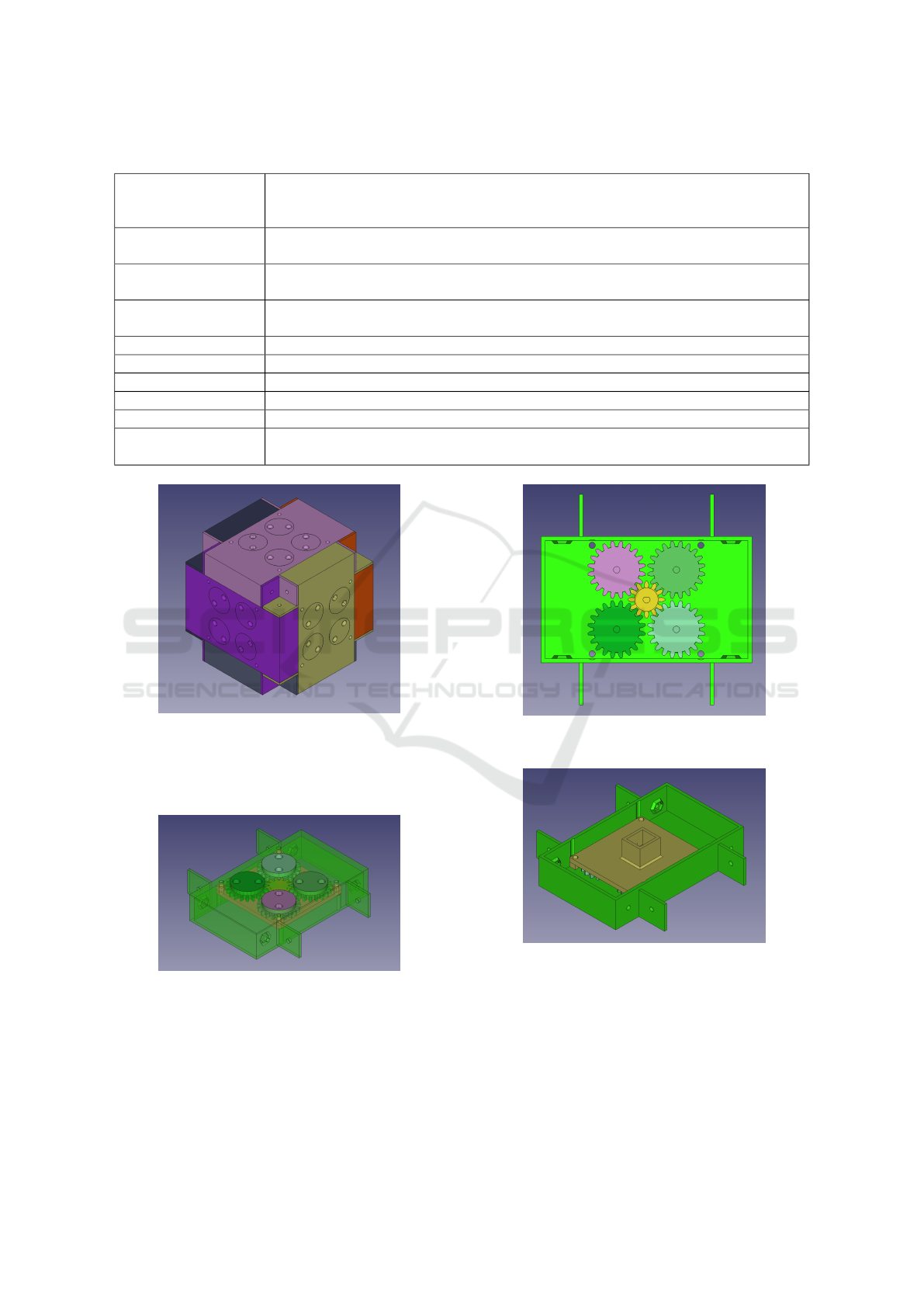
Table 1: Modular Robotic platforms grouped by inter-module communication protocol.
IR (Yim, 1994) (Murata et al., 1994) (Rus and Vona, 2000) (Castano et al., 2002)
(Suh et al., 2002) (Koseki et al., 2004) (Salemi et al., 2006) (Shimizu et al., 2006)
(Jørgensen et al., 2004) (Gilpin et al., 2008) (Dorigo et al., 2013) (Salem, 2014)
CAN (Yim et al., 2000) (Yim et al., 2007) (Yerpes et al., 2008) (Wei et al., 2010) (Baca
et al., 2012) (Pfotzer et al., 2014) (Fai
˜
na et al., 2015) (Parrott, 2016)
Bluetooth (Moeckel et al., 2006) (Wolfe et al., 2012) (Jia et al., 2015) (Yerpes et al., 2008) (Baca
et al., 2012) (Parrott, 2016) (Ryland and Cheng, 2010)
2.4GHz Wireless (Zhu et al., 2013) (Pacheco et al., 2015) (Fai
˜
na et al., 2015) (Oung and D’Andrea,
2011)
WiFi (Dorigo, 2005) (Ryland and Cheng, 2010) (O’Hara et al., 2014) (Davey et al., 2012)
Zigbee (Romanishin et al., 2013) (Zhang et al., 2014) (Baca et al., 2014) (Wei et al., 2010)
RS485 (Kotay et al., 1998) (Murata et al., 2002) (Lyder et al., 2008) (Lyder et al., 2010)
I2C (Daidi
´
e et al., 2007) (Zhang et al., 2008) (Gambao et al., 2005)
UART (Oung and D’Andrea, 2011) (Thakker et al., 2014) (Kee et al., 2014)
Others (Neubert and Lipson, 2016) (Fukuda and Kawauchi, 1990) (
¨
Unsal et al., 1999) (Zykov
and Lipson, 2007) (Liedke et al., 2013) (White et al., 2004) (Gilpin et al., 2010)
Figure 2: CAD render of full module composed of six sub-
modular tiles.
connection mechanism can be seen in Figure 4 The
mounting for the motor can be seen in Figure 5.
Figure 3: CAD render with translucent sub-modular tile de-
picting the connection mechanism.
The connection mechanism has three states of op-
eration.
• Active Connect - In this state the magnet poles
of the face are aligned with the opposing magnet
poles of the opposite face. This creates a net at-
Figure 4: CAD render depicting the gearing of the connec-
tion mechanism.
Figure 5: CAD render depicting the motor mount for the
magnetic connector actuation.
tract force between modules and holds them to-
gether.
• Active Disconnect - In this state the magnet poles
of the face are aligned with the same magnet poles
of the opposite face, this creates a net repel force
between modules and pushes them apart.
ICINCO 2022 - 19th International Conference on Informatics in Control, Automation and Robotics
388
• Passive - In this state the magnet poles of the face
are 90 degrees offset from the magnet poles of
the opposing face, this creates a net zero force be-
tween the modules.
The tiles are assembled into a full module using
M3 bolts with corresponding nuts embedded into each
tile. This allows for disassembly on a per-tile basis.
3.2 Electronics
This section describes the electronic design to realise
a full module.
3.2.1 Electronics Architecture
The architecture of the electronics in a module is cen-
tered around a Xilinx Zynq 7020 SoC, which con-
tains two arm processing cores and Artix-7 FPGA
fabric. The FPGA portion of the device is utilised
for all networking protocol implementation, connect-
ing to 6 Ethernet physical layer transceivers, the TI
DP83825. Each tranceiver then connects to the corre-
sponding tile in the module, which contains the Eth-
ernet transformer, and connection to the tile magnets.
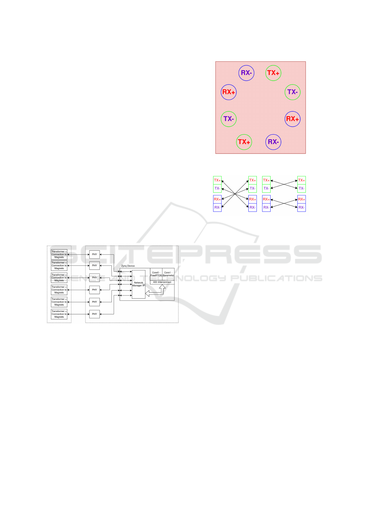
An overview of this architecture is shown in Figure 6.
Figure 6: Block diagram depicting the architecture of the
electronics in a module.
3.2.2 Networking
As identified above, there is a need for significant
improvement in networking of systems of modular
robots. A network supporting a modular robotic sys-
tem must be resilient to a dynamically reconfiguring
physical topology. It must also support both time
critical control commands and high bandwidth sensor
streams propagating through the system. The IEEE
802.3 100Base-TX Ethernet standard was used as a
basis for the network hardware layer. 100Base-TX
Ethernet uses two twisted pairs of copper conduc-
tors to operate full-duplex 100Mbps communication.
One major benefit identified for modular robots is that
some Ethernet physical layer ICs have the ability to
Figure 7: Configuration of Ethernet conductors on tile mag-
nets.
Figure 8: Ethernet connection permutations.
detect and correct for crossover of pairs and crossover
of conductors in pairs. This means that, when the con-
ductors are arranged correctly, two modules can con-
nect in any orientation and the Ethernet PHY IC will
identify the connection configuration operate as nor-
mal. The Ethernet data pairs are connected between
modules using the magnets that mechanically hold the
modules as conductors. Each conductor is connected
to two seperate magnets, in the configuration shown
in Figure 7. This configuration, where each conductor
is routed through opposing sides of the magnet face,
allows two tiles to connect in any orientation, and still
maintain an active Ethernet channel. This configura-
tion yields the connection permutations between two
nodes shown in 8. These permutations are repeated at
180 degree rotation intervals.
3.2.3 Power Distribution
In using transformer-isolated Ethernet as the con-
nection between modules, power can be distributed
between modules using a modified version of the
802.3af power over Ethernet (PoE) standard. This is
achieved by imposing a common mode voltage be-
tween the data pairs of the Ethernet channel via the
center tap of the Ethernet transformer. This allows
power and data to be shared between modules using
the same conductors, reducing the need for more elec-
trical contacts between modules which increases the
complexity of the design. Work is ongoing to im-
plement this into a module design, but initial tests
A Novel Connection Mechanism for Dynamically Reconfigurable Modular Robots
389

have been done to verify the feasibility of transmit-
ting power and data over an Ethernet channel with
magnetic conductors with success.
4 SIMULATION
This section describes the simulation environment de-
veloped to aid development of of the software for this
modular robotic platform. The simulation environ-
ment models both the mechanical properties of mod-
ules, and the communication channel used for module
interconnection.
4.1 Simulation Overview
To enable development of networking protocols, re-
configuration algorithms, and task planning in this
modular robotic system, a holistic simulation envi-
ronment has been created to model the relevant as-
pects of the system. The simulation environment con-
tains two main components. The physical simulation
is performed using the Unity engine, and a custom
POSIX compliant network simulator has been created
to accurately model the network interconnections be-
tween modules. The network simulator is cyclically
triggered from the Unity simulator. Arbitrary module
configurations can be created in the simulator. Cur-
rently a model of a kinematically static module and a
wheel module exists. With this, modular rovers can
be created in simulation, like that shown in Figure 9
Figure 9: A modular rover configuration in simulation.
Work is ongoing to perform experiments in simu-
lation. Currently, some initial experiments have been
run to test the models of the network side of the
simulator. Experiments were run on a 3x3x3 mod-
ule strictly orthogonal network of kinematically static
modules. A broadcast packet is sent from one of the
corner modules, and the time taken for that packet
to reach all other modules in the system is recorded.
This experiment is repeated with packet payload sizes
from 1-5 bytes. The results from this experiment is
shown in Figure 10. These results show the latency of
the packet propagation increasing with payload size
as expected. A render of the network of modules used
in this simulation is shown in Figure 11. Once full
integration of a module’s mechanical and electronic
components have been created, this experiment can
be repeated in hardware to test the reality gap of the
simulator, and tune the parameters of the models used.
Figure 10: Simulation results of propagation delay of a
broadcast packet in a strictly orthogonal network for vary-
ing packet payload sizes (bytes).
Figure 11: Render of a 3x3x3 strictly orthogonal network
of modules in simulation.
4.2 Simulation Experimental Plan
Work is ongoing to perform more experiments in sim-
ulation. Now that hardware development is nearing
completion, work can be done to implement topology
discovery and routing protocols for the dynamically
reconfigurable modular system. Once these imple-
mentations are completed, these can be tested in simu-
lation to test their performance against other systems.
The network model can be modified to accurately
model other communications channels including SPI,
CAN, UART, IR, etc. This will allow for quantitative
performance comparison between the system imple-
mented here and other communication systems used
in other research projects.
ICINCO 2022 - 19th International Conference on Informatics in Control, Automation and Robotics
390
5 HARDWARE
IMPLEMENTATION
This section describes the current implementation of
the module design described in the previous section.
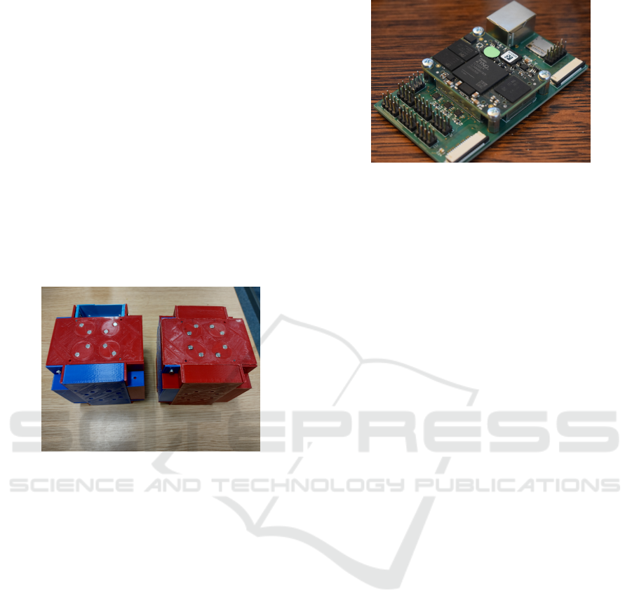
5.1 Module Mechanical Implementation
The mechanical components of the modules have
been 3D printed in PLA+. All printing was done on
an Intamsys Funmat HT 3D printer. Images of an as-
sembled tile and module can be seen in 12. The left
module is in passive state, the right module is in active
connect state. Tests have been carried out to verify
that the connection mechanism works as described.
A video showing the transition from active connect to
disconnect can be seen at (White, 2022a).
Figure 12: Left: assembled module in passive connection
state. Right: assembled module in active connection state.
5.2 Module Electronics
A PCB has been designed and manufactured, shown
in Figure 13, around a Trenz electronic TE0720 Sys-
tem on Module (SoM). The SoM is a 4cm x 5cm
PCB that contains a Zynq 7010 System on Chip
(SoC), 1GB DDR3 RAM and 8Gb e.MMC non-
volatile memory. It is designed to connect to a custom
carrier board with board to board connectors for ap-
plication specific uses. The carrier board designed for
this project contains six TI DP83825 Ethernet PHY
ICs, two CSI camera connectors, an SD card slot and
connections for power, programming and GPIO ac-
cess.
6 FUTURE HARDWARE
DEVELOPMENT PLANS
Current hardware development has concluded the
prototyping phase of the project. In the coming
months a number of modules are to be developed and
Figure 13: The compute module PCB populated with the
TE0720 SoM.
integration of system components completed to cre-
ate a working modular robotics platform to demon-
strate the work done here. To create a useful system,
more than just kinematically static modules will have
to be created, currently there are a number of hetero-
geneous modules scheduled for development.
6.1 Wheel Module
This module has a face with a motorised wheel at-
tached to it. Each of the other five faces contain an
inter-module connection mechanism. There is a net-
worked microcontroller in the module with the appro-
priate motor control electronics along with the net-
work processing FPGA.
6.2 Joint Module
A joint module contains 1 to 3 rotational degrees of
freedom. These modules will allow the system to
form kinematic chains for locomotion or manipula-
tion of objects.
6.3 Sensor Module
A sensor module is a kinematically static module with
a sensor attached to one or more faces. To date a cam-
era module has been developed. There are plans to de-
velop a module with rangefinders to aid in localisation
and obstacle detection tasks. The benefit of having
dedicated sensor modules is that they can be moved
around the morphology of modules as required by the
system for a given task.
7 CONCLUSION
This paper has presented the work done to date on a
novel interconnection mechanism for dynamically re-
configurable modular robotics. The system described
A Novel Connection Mechanism for Dynamically Reconfigurable Modular Robots
391

in this paper includes mechanical connection by way
of rotating permanent magnets, communication us-
ing Ethernet for the physical layer utilizing the mag-
nets as the electrical connection between modules,
and power sharing via a modified power over Eth-
ernet system using the same conductors as the data
pairs. The system has been successfully protoyped
and mechanically tested, work is ongoing to integrate
the electronics and mechanical hardware together to
perform holistic testing. Initial experiments have been
performed in simulation to assess the accuracy of the
network simulator. Work is ongoing to perform ex-
periments with rover modules, and implement proto-
cols for topology discovery and routing of data pack-
ets through the system.
REFERENCES
Ahmadzadeh, H., Masehian, E., and Asadpour, M. (2016).
Modular robotic systems: Characteristics and appli-
cations. Journal of Intelligent and Robotic Systems:
Theory and Applications, 81(3-4):317–357.
Baca, J., Ferre, M., and Aracil, R. (2012). A heterogeneous
modular robotic design for fast response to a diversity
of tasks. Rob. Auton. Syst., 60(4):522–531.
Baca, J., Hossain, S. G. M., Dasgupta, P., Nelson, C. A.,
and Dutta, A. (2014). ModRED: Hardware design
and reconfiguration planning for a high dexterity mod-
ular self-reconfigurable robot for extra-terrestrial ex-
ploration. Rob. Auton. Syst., 62(7):1002–1015.
Brunete, A., Ranganath, A., Segovia, S., de Frutos, J. P.,
Hernando, M., and Gambao, E. (2017). Current trends
in reconfigurable modular robots design. Int. J. Adv.
Rob. Syst., 14(3):172988141771045.
Castano, A., Behar, A., and Will, P. M. (2002). The
conro modules for reconfigurable robots. IEEE/ASME
Trans. Mechatron., 7(4):403–409.
Daidi
´
e, D., Barbey, O., Guignard, A., Roussy, D., Guenter,
F., Ijspeert, A., and Billard, A. (2007). The DoF-box
project: An educational kit for configurable robots.
IEEE/ASME International Conference on Advanced
Intelligent Mechatronics, AIM.
Davey, J., Kwok, N., and Yim, M. (2012). Emulating self-
reconfigurable robots - design of the SMORES sys-
tem. Rep. U. S., pages 4464–4469.
Dorigo, M. (2005). Swarm-bot: An experiment in swarm
robotics. Proceedings - 2005 IEEE Swarm Intelli-
gence Symposium, SIS 2005, 2005:199–207.
Dorigo, M., Floreano, D., Gambardella, L. M., Mondada,
F., Nolfi, S., Baaboura, T., Birattari, M., Bonani, M.,
Brambilla, M., Brutschy, A., Burnier, D., Campo,
A., Christensen, A. L., Decugniere, A., Di Caro,
G., Ducatelle, F., Ferrante, E., F
¨
orster, A., Gonzales,
J. M., Guzzi, J., Longchamp, V., Magnenat, S., Math-
ews, N., Montes De Oca, M., O’Grady, R., Pinciroli,
C., Pini, G., R
´
etornaz, P., Roberts, J., Sperati, V., Stir-
ling, T., Stranieri, A., St
¨
utzle, T., Trianni, V., Tuci,
E., Turgut, A. E., and Vaussard, F. (2013). Swar-
manoid: A novel concept for the study of heteroge-
neous robotic swarms. IEEE Robot. Autom. Mag.,
20(4):60–71.
Fai
˜
na, A., Bellas, F., Orjales, F., Souto, D., and Duro,
R. J. (2015). An evolution friendly modular archi-
tecture to produce feasible robots. Rob. Auton. Syst.,
63(P2):195–205.
Feczko, J., Manka, M., Krol, P., Giergiel, M., Uhl, T., and
Pietrzyk, A. (2015). Review of the modular self re-
configurable robotic systems. 2015 10th International
Workshop on Robot Motion and Control, RoMoCo
2015, pages 182–187.
Fukuda, T. and Kawauchi, Y. (1990). Cellular robotic
system (CEBOT) as one of the realization of self-
organizing intelligent universal manipulator. pages
662–667.
Fukuda, T. and Nakagawa, S. (1988). Dynamically recon-
figurable robotic system. In Proceedings. 1988 IEEE
International Conference on Robotics and Automa-
tion, pages 1581–1586 vol.3.
Gambao, E., Brunete, A., and Hernando, M. (2005). Multi-
configurable inspection robots for low diameter canal-
izations. In 22nd ISARC. unknown.
Gilpin, K., Knaian, A., and Rus, D. (2010). Robot peb-
bles: One centimeter modules for programmable mat-
ter through self-disassembly. Proceedings - IEEE In-
ternational Conference on Robotics and Automation,
pages 2485–2492.
Gilpin, K., Kotay, K., Rus, D., and Vasilescu, I.
(2008). Miche: Modular shape formation by Self-
Disassembly. Int. J. Rob. Res., 27(3-4):345–372.
Jia, X., Frenger, M., Chen, Z., Hamel, W. R., and Zhang, M.
(2015). An alligator inspired modular robot. Proceed-
ings - IEEE International Conference on Robotics and
Automation, 2015-June(June):1949–1954.
Jørgensen, M. W., Østergaard, E. H., and Lund, H. H.
(2004). Modular ATRON: Modules for a self-
reconfigurable robot. Rep. U. S., 2:2068–2073.
Kee, V., Rojas, N., Elara, M. R., and Sosa, R. (2014).
Hinged-Tetro : A self-recon fi gurable module for
nested recon fi guration. pages 1539–1546.
Koseki, M., Minami, K., and Inou, N. (2004). Cellular
robots forming a mechanical structure ( evaluation of
structural formation and hardware design of “ CHO-
BIE II ”). Proceedings of 7th International Sym-
posium on Distributed Autonomous Robotic Systems
(DARS04), pages 131–140.
Kotay, K., Rus, D., Vona, M., and McGray, C. (1998). The
self-reconfiguring robotic molecule. Proceedings -
IEEE International Conference on Robotics and Au-
tomation, 1:424–431.
Liedke, J., Matthias, R., Winkler, L., and Worn, H. (2013).
The collective self-reconfigurable modular organism
(CoSMO). 2013 IEEE/ASME International Confer-
ence on Advanced Intelligent Mechatronics: Mecha-
tronics for Human Wellbeing, AIM 2013, pages 1–6.
Lyder, A., Franco, R., Garcia, M., and Stoy, K. (2010).
Genderless connection mechanism for modular robots
introducing torque transmission between modules.
ICINCO 2022 - 19th International Conference on Informatics in Control, Automation and Robotics
392

ICRA 2010 Workshop on Modular Robots: The State
of the Art, pages 77–82.
Lyder, A., Garcia, R. F. M., and Stoy, K. (2008). Me-
chanical design of odin, an extendable heterogeneous
deformable modular robot. 2008 IEEE/RSJ Interna-
tional Conference on Intelligent Robots and Systems,
IROS, pages 883–888.
Moeckel, R., Jaquier, C., Drapel, K., Dittrich, E., Upegui,
A., and Ijspeert, A. (2006). YaMoR and bluemove -
an autonomous modular robot with bluetooth interface
for exploring adaptive locomotion. Proceedings of the
8th International Conference on Climbing and Walk-
ing Robots and the Support Technologies for Mobile
Machines, CLAWAR 2005, pages 685–692.
Moubarak, P. and Ben-Tzvi, P. (2012). Modular and recon-
figurable mobile robotics.
Murata, S., Kurokawa, H., and Kokaji, S. (1994). Self- as
sembling machine. pages 3–10.
Murata, S., Yoshida, E., Kamimura, A., Kurokawa, H.,
Tomita, K., and Kokaji, S. (2002). M-TRAN : Self-
Reconfigurable modular. 7(4):431–441.
Neubert, J. and Lipson, H. (2016). Soldercubes: a self-
soldering self-reconfiguring modular robot system.
Auton. Robots, 40(1):139–158.
O’Hara, I., Paulos, J., Davey, J., Eckenstein, N., Doshi, N.,
Tosun, T., Greco, J., Seo, J., Turpin, M., Kumar, V.,
and Yim, M. (2014). Self-assembly of a swarm of au-
tonomous boats into floating structures. Proceedings
- IEEE International Conference on Robotics and Au-
tomation, pages 1234–1240.
Oung, R. and D’Andrea, R. (2011). The distributed flight
array. Mechatronics, 21(6):908–917.
Pacheco, M., Fogh, R., Lund, H. H., and Christensen,
D. J. (2015). Fable II: Design of a modular robot
for creative learning. Proceedings - IEEE Interna-
tional Conference on Robotics and Automation, 2015-
June(June):6134–6139.
Parrott, C. (2016). A hybrid and extendable self-
reconfigurable modular robotic system. PQDT - UK
& Ireland, (September).
Pfotzer, L., Ruehl, S., Heppner, G., Roennau, A., and
Dillmann, R. (2014). KAIRO 3: A modular recon-
figurable robot for search and rescue field missions.
2014 IEEE International Conference on Robotics and
Biomimetics, IEEE ROBIO 2014, pages 205–210.
Romanishin, J. W., Gilpin, K., and Rus, D. (2013). M-
blocks: Momentum-driven, magnetic modular robots.
Rep. U. S., pages 4288–4295.
Rus, D. and Vona, M. (2000). Physical implementation of
the self-reconfiguring crystalline robot. Proceedings
- IEEE International Conference on Robotics and Au-
tomation, 2(April):1726–1733.
Ryland, G. G. and Cheng, H. H. (2010). Design of imobot,
an intelligent reconfigurable mobile robot with novel
locomotion. Proceedings - IEEE International Con-
ference on Robotics and Automation, pages 60–65.
Saab, W., Racioppo, P., and Ben-Tzvi, P. (2019). A review
of coupling mechanism designs for modular reconfig-
urable robots. Robotica, 37(2):378–403.
Salem, B. (2014). PetRo: Development of a modular pet
robot. Proceedings - IEEE International Workshop on
Robot and Human Interactive Communication, 2014-
Octob(October):483–488.
Salemi, B., Moll, M., and Shen, W. M. (2006). SUPER-
BOT: A deployable, multi-functional, and modular
self-reconfigurable robotic system. In IEEE Interna-
tional Conference on Intelligent Robots and Systems,
pages 3636–3641.
Shimizu, M., Mori, T., and Ishiguro, A. (2006). A develop-
ment of a modular robot that enables adaptive recon-
figuration. Rep. U. S., pages 174–179.
Suh, J. W., Homans, S. B., and Yim, M. (2002). Telecubes:
Mechanical design of a module for self-reconfigurable
robotics. Proceedings-IEEE International Conference
on Robotics and Automation, 4(May):4095–4101.
Thakker, R., Kamat, A., Bharambe, S., Chiddarwar, S., and
Bhurchandi, K. M. (2014). ReBiS - reconfigurable
bipedal snake robot. Rep. U. S., (Iros):309–314.
¨
Unsal, C., K
´
yl
´
yc¸c¸
¨
ote, H., and Khosla, P. K. (1999). I (
CES ) -cubes : a modular self-reconfigurable bipartite
robotic system. 3839(September):258–269.
Wei, H., Cai, Y., Li, H., Li, D., and Wang, T. (2010).
Sambot: A self-assembly modular robot for swarm
robot. Proceedings - IEEE International Conference
on Robotics and Automation, (37):66–71.
White, J. (2022a). Modules transitioning from active con-
nect to disconnect. https://drive.google.com/file/d/1L
guGgAUJV8ZAn0tjlJI0c QNWTqaDV8s/view?usp
=sharing.
White, J. (2022b). Rotating magnets video. https://drive.
google.com/file/d/1DWoGVY6MG2so2Z5zRYEIjCq
G-bsxUu3V/view?usp=sharing.
White, P. J., Kopanski, K., and Lipson, H. (2004). Stochas-
tic self-reconfigurable cellular robotics. Proceedings
- IEEE International Conference on Robotics and Au-
tomation, 2004(3):2888–2893.
Wolfe, K. C., Moses, M. S., Kutzer, M. D. M., and
Chirikjian, G. S. (2012). M3Express: A low-cost
independently-mobile reconfigurable modular robot.
Proceedings - IEEE International Conference on
Robotics and Automation, pages 2704–2710.
Yerpes, A., Baca, J., Escalera, J. A., Ferre, M., Aracil, R.,
and Crespo, A. (2008). Modular robot based on 3 ro-
tational DoF modules. 2008 IEEE/RSJ International
Conference on Intelligent Robots and Systems, IROS,
pages 889–894.
Yim, M. (1994). New locomotion gaits. Proceedings -
IEEE International Conference on Robotics and Au-
tomation, (pt 3):2508–2514.
Yim, M., Duff, D. G., and Roufas, K. D. (2000). Poly-
Bot: a modular reconfigurable robot. In Proceedings
- IEEE International Conference on Robotics and Au-
tomation, volume 1, pages 514–520.
Yim, M., Roufas, K., Duff, D., Zhang, Y., Eldershaw,
C., and Homans, S. (2003). Modular reconfigurable
robots in space applications. Auton. Robots.
Yim, M., Shen, W. M., Salemi, B., . . . , D. R. I. R. ., and
2007, U. Modular self-reconfigurable robot systems.
ieeexplore.ieee.org.
A Novel Connection Mechanism for Dynamically Reconfigurable Modular Robots
393

Yim, M., Shirmohammadi, B., Sastra, J., Park, M., Dugan,
M., and Taylor, C. J. (2007). Towards robotic self-
reassembly after explosion. Rep. U. S., pages 2767–
2772.
Zhang, H., Gonzalez-Gomez, J., Xie, Z., Cheng, S., and
Zhang, J. (2008). Development of a low-cost flexible
modular robot GZ-I. IEEE/ASME International Con-
ference on Advanced Intelligent Mechatronics, AIM,
pages 223–228.
Zhang, Y., Song, G., Liu, S., Qiao, G., . . . , J. Z. J. o. I. ., and
2016, U. (2014). A modular self-reconfigurable robot
with enhanced locomotion performances: design,
modeling, simulations, and experiments. Springer.
Zhu, Y., Zhao, J., Cui, X., Wang, X., Tang, S., Zhang, X.,
and Yin, J. (2013). Design and implementation of
UBot: A modular Self-Reconfigurable robot. 2013
IEEE International Conference on Mechatronics and
Automation, IEEE ICMA 2013, pages 1217–1222.
Zykov, V. and Lipson, H. (2007). Experiment design
for stochastic Three-Dimensional reconfiguration of
modular robots. Intelligent Robots and Systems, 2007.
IROS 2007. IEEE/RSJ International Conference on,
pages 2–5.
ICINCO 2022 - 19th International Conference on Informatics in Control, Automation and Robotics
394
