
Modelling and Simulation of an Aerosol-on-Demand Print Head
with Computational Fluid Dynamics
Martin Ungerer
1
, David Zeltner
1
, Achim Wenka
2
, Ulrich Gengenbach
1a
and Ingo Sieber
1b
1
Institute for Automation and Applied Informatics, KIT, Hermann-von-Helmholrz-Platz1, 76344 Egg.-Leo, Germany
2
Institute for Micro Process Engineering, KIT, Hermann-von-Helmholrz-Platz1, 76344 Egg.-Leo, Germany
Keywords: Computational Fluid Dynamics, Modelling, Simulation, Additive Manufacturing.
Abstract: In this paper we present the functional validation of a newly developed concept of a print head for aerosol-
on-demand printing using fluid dynamical modelling and simulation. In our concept of the aerosol-on-demand
print head, the ink is atomised by ultrasonic excitation and focussed by a sheath gas in a converging nozzle.
The special feature of this new concept is aerosol generation directly in the print head thus allowing for on-
demand operation. Using computational fluid dynamics (CFD), a pre-manufacturing study is being carried
out to validate the operation of the concept as well as to find a design-for-manufacture.
1 INTRODUCTION
Novel devices and systems with special chemical,
physical or optical properties can be realised by
printing processes using functionalized inks
(Sirringhaus and Shimoda 2003; Sieber, Thelen, and
Gengenbach 2020, 2021; Magdassi 2010). Drop-on-
demand inkjet printing has achieved a high level of
development in printing functional structures
(Sirringhaus and Shimoda 2003). In contrast to drop-
on-demand inkjet printing, aerosol jet printing has the
advantages of potentially printing finer structures
with higher resolution and the capability to print on
three dimensional structures (Mette et al. 2007,
Neotech 2021), or even bond multiple chip layer
together, thus replacing the need for wire bonding
(Hedges and Marin 2012).
Aerosol jet printing is a continuous printing
process where a fine spray of atomised ink is focussed
hydrodynamically by means of a sheath gas flow.
This results in a stable, and over a range of several
millimetres well-collimated aerosol jet (Ganz et al.
2016; Gupta et al. 2016). A currently unsolved
problem in aerosol jet printing is, that it cannot be
operated in on-demand mode. This is because a run-
in time of the aerosol generation is required, since in
current aerosol jet printers the generation of the
aerosol takes place in an atomisation unit which is
a
https://orcid.org/0000-0001-9762-0019
b
https://orcid.org/0000-0003-2811-7852
detached from the nozzle. Thus, switching the jet
generation on and off for on-demand operation is not
possible (Chang, Facchetti, and Reuss 2017; Hedges
and Marin 2012).
To address this point we develop a new principle
for an aerosol jet-on-demand (AoD) print head
(Ungerer et al. 2018). Centerpiece of this concept is
the integration of the atomisation unit into the print
head. The aerosol is generated by means of ultrasonic
atomisation of the ink in the capillary with the aid of
a piezo actuator. Aerodynamical focusing of the
aerosol jet is based on the sheath gas mass flow, the
aerosol mass flow and the outlet nozzle. Thus, a
compact system design can be developed which will
allow for printing operation in all spatial directions, a
widely tunable nozzle-to-substrate distance, as well
as a jet-on-demand mode of operation (Ungerer
2020; Sieber et al. 2022).
This paper will focus on the proof-of-concept
based on CFD simulations. In the simulations the
functional ink is modelled as distilled water. This is
justified, since the aerodynamic focusing is
independent of the dynamic viscosity of the fluid or
the particle content in the fluid. Hence, an
aerodynamic focusing of all fluids that can be
atomised in the capillary is possible. For modelling of
the print head the limitations of the manufacturing
processes used (design-for-manufacturing) are taken
44
Ungerer, M., Zeltner, D., Wenka, A., Gengenbach, U. and Sieber, I.
Modelling and Simulation of an Aerosol-on-Demand Print Head with Computational Fluid Dynamics.
DOI: 10.5220/0011258100003274
In Proceedings of the 12th International Conference on Simulation and Modeling Methodologies, Technologies and Applications (SIMULTECH 2022), pages 44-51
ISBN: 978-989-758-578-4; ISSN: 2184-2841
Copyright
c
2022 by SCITEPRESS – Science and Technology Publications, Lda. All rights reserved
into account. The organisation of this paper is as
follows: Section 2 addresses the design-for-
manufacturing of a laboratory setup of the print head.
In Section 3, modelling of the print head is presented.
Herein a brief theoretical description of the used
model approach is presented as well as the geometry
model and the meshing. Simulation and its results are
presented in Section 4, the paper concludes with a
discussion of the results and a brief outlook in
Section 5.
2 DESIGN-FOR-MANUFACTURING
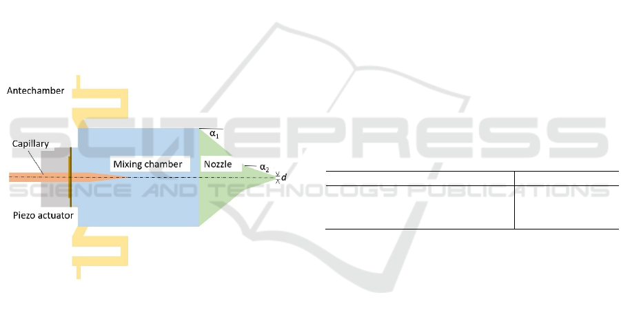
Fig. 1 shows the schematic of the principle design of
the inner contour of the aerosol print head. The
aerosol is generated by ultrasonic atomisation of the
ink in the capillary with the aid of a piezo actuator.
The tip of the capillary is located in a rotationally
symmetric chamber, the mixing chamber, into which
a sheath gas is injected to aerodynamically focus the
atomised ink in the nozzle.
Figure 1: Schematic of the principle design.
In order to obtain a uniform, rotationally
symmetric aerosol jet, a uniform flow of the sheath
gas around the capillary is necessary. To achieve this,
the velocity profile of the sheath gas, which flows in
from four inlets evenly distributed around the
circumference, is homogenised in a plenum chamber,
denoted as antechamber. The concept of a plenum
chamber for homogenisation is well known in fluid
mechanics (Guha, 2010) and rules of thumb exist to
achieve good mixing and thus homogenisation using
a large volume, many baffles and the longest possible
distance in the antechamber. Hence, the antechamber
is designed as a meandering structure, which makes
good use of the given volume, has a long distance and
sharp deflections at the bending, thus leading to
homogeneous flow around the capillary.
Downstream of the mixing a nozzle follows in
which the ink droplets are aerodynamically focused.
Due to the aerosol generation inside of the mixing
chamber, discontinuous operation is possible and thus
enables the feature of AoD printing.
For manufacturing of a functional model of the
aerosol print head for future use in a laboratory setup,
a lathing process is available at our institute. Lathing
is a process well suited to manufacture the almost
completely rotationally symmetrical geometry of the
print head. Also, surfaces with sufficiently low
roughness can be achieved by lathing. The
application of the lathing process results in a number
of requirements which must be taken into account in
the design of the print head. For example, the shallow
angles required for aerodynamic focusing cannot be
produced with the conventional lathing tool due to its
limited insertion depth. This leads to a separation of
the nozzle geometry into two sections: One with a
nozzle angle of α
1
= 45°, which can be produced with
the standard lathing tool, and a tip with a nozzle angle
of α
2
= 15°, which is used for focusing the aerosol.
This tip is manufactured with a conical milling tool.
The minimum diameter of the nozzle exit, which can
be manufactured with the conical milling tool, is 1
mm. The design parameters resulting from the
process limitations are summarised in Table 1.
Table 1: Design parameters of the fabrication process.
Parameter Value
Nozzle angle α
1
[°]
Nozzle angle α
2
[°]
Nozzle exit diameter d [mm]
45
15
1
As material for the print head, the aluminum alloy
AlMgSi1 is selected. These are the boundary
conditions resulting from the fabrication processes
used to be considered in geometrical modelling of the
print head.
3 MODELLING
Modelling of the AoD-print head is on the basis of
CFD, a numerical technique used to solve fluid
mechanical problems. We are using Ansys Fluent in
the versions R19.3 and R20.1 as CFD tool.
3.1 Theory
Our chosen modelling approach also takes turbulent
flows into account. In principle, turbulence is
described by the Navier-Stokes equations. However,
a direct numerical simulation based on the Navier-
Modelling and Simulation of an Aerosol-on-Demand Print Head with Computational Fluid Dynamics
45

Stokes equations is not possible in most cases and
averaging techniques are used to filter out all or at
least parts of the turbulent spectrum (Ansys 2021).
Ansys Fluent offers a large number of different
turbulence models, none of which can be regarded as
universally valid. For the work presented, we have
used the Reynolds-averaged Navier-Stokes equations
(Eqs. 1, 2).
𝜕𝜌
𝜕𝑡
+
𝜕
𝜕𝑥
𝜌𝑢
=0
(1)
𝜕
𝜕𝑡
𝜌𝑢
+
𝜕
𝜕𝑥
𝜌𝑢
𝑢
=
−
𝜕𝑝
𝜕𝑥
+
𝜕
𝜕𝑥
𝜇
𝜕𝑢
𝜕𝑥
+
𝜕𝑢
𝜕𝑥
−
2
3
𝛿
𝜕𝑢
𝜕𝑥
+
𝜕
𝜕𝑥
−𝜌𝑢
𝑢
(2)
Eq. 1 is the continuity equation, describing the
conservation of mass where ρ is the density and u
i
is
the mean velocity. The conservation of momentum is
represented by Eq. 2 where p is the static pressure and
the symbol 𝛿
denotes the Kronecker-Delta. The
Reynolds-averaged Navier-Stokes equations
equations are generally favourable in terms of
computational effort and time and are thus very well
suited for the calculation of complex turbulent flows
(Ansys 2021). By eliminating all turbulent structures
from the flow, a uniform flow of the averaged
velocity and pressure fields is achieved. Based on the
Reynolds-averaged Navier-Stokes equations
equations a large variety of engineering applications
can be modeled. For our approach, we use the k-𝜔-
𝑆𝑆𝑇 model (shear stress transport) which is a
compressible turbulence model. Here, two additional
transport equations are solved, one for the turbulence
kinetic energy 𝑘 (Eq. 3) and one for the specific
dissipation rate 𝜔 (Eq. 4).
𝜕
𝜕𝑡
𝜌𝑘
+
𝜕
𝜕𝑥
𝜌𝑘𝑢
=
𝜕
𝜕𝑥
Γ
𝜕𝑘
𝜕𝑥
+ 𝐺
−𝑌
+ 𝑆
(3)
𝜕
𝜕𝑡
𝜌𝜔
+
𝜕
𝜕𝑥
𝜌𝜔𝑢
=
𝜕
𝜕𝑥
Γ
𝜕𝜔
𝜕𝑥
+ 𝐺
−𝑌
+ 𝐷
+ 𝑆
(4)
With 𝐺
representing the production of turbulence
kinetic energy 𝑘 and 𝐺
the generation of the specific
dissipation rate 𝜔 . 𝛤
and 𝛤
give the effective
diffusivity of 𝑘 and 𝜔, respectively, while 𝑌
and 𝑌
imply the dissipation of 𝑘 and 𝜔 due to turbulence.
𝐷
is the cross-diffusion term, 𝑆
and 𝑆
are user-
defined sources, respectively. Detailed information of
the calculation of this parameter can be found in
Wilcox (2006) and Menter (1994).
The main advantage of the k-𝜔 model is that the
boundary layers are also modelled thus leading to
better results near the walls. In addition, on the basis
of k-𝜔 models boundary layer flows with
unfavourable pressure gradient and dissipation can be
better predicted. In the k-ω models of the SST,
elements of the ω-equation and the ε-equation are
combined to avoid the sensitivity with respect to free
flow inherent to the standard k-ω model.
Furthermore, the SST model is calibrated to
accurately calculate flow separation from smooth
surfaces.
Modelling of the aerosol takes place with respect
to the Euler-Lagrange consideration as discrete
phases. In the Discrete Phase Model the droplet tracks
are calculated inside of the velocity field of the
continuous phase. The Euler-Lagrange approach
neglects particle-particle interactions, and this
requires that the discrete phase occupies only a low
volume fraction (Ansys 2021). Since we estimate a
volume fraction of the discrete phase of less than 10%
of the total volume, the Euler-Lagrange consideration
is well suited for efficient calculation of the
individual droplets due to the small total number of
droplets per volume fraction. The source
characteristic of the aerosol generation is modelled
using the cone injection model of Ansys Fluent which
describes a conic-shaped particle injection for the
aerosol where the following input parameters are
available: Origin, particle distribution, temperature,
cone axis, aerosol velocity, cone angle, particle
diameter, mass flow, and the azimuth. The properties
set in the model are shown in Tab. 2.
Table 2: Injection properties.
Parameter Value
x-Position [m]
y- Position [m]
z- Position [m]
Particle distribution
Particle diameter [m]
Temperature [K]
Cone axis
Cone angle [°]
Azimuthal start angle [°]
Azimuthal stop angle [°]
Velocity magnitude [m/s]
Mass flow [kg/s]
0
0
0
uniform
2⋅ 10
-5
300
(1/0/0)
25
0
360
10
p
aramete
r
3.2 Geometry
The geometry model must strictly follow the
conditions and design rules of the manufacturing
processes as defined in Section 2 and summarised in
Tab. 1. Geometry parameters, which do not have a
direct impact on the focussing of the aerosol jet, as
long as they are within specific boundaries, are:
SIMULTECH 2022 - 12th International Conference on Simulation and Modeling Methodologies, Technologies and Applications
46
dimensions of the mixing chamber and
position and angle of the influx channel.
Length and width of the mixing chamber can be
freely chosen, as long as they are sufficiently large to
avoid a wetting of the inner walls by insufficient
focussing. Manufacturing restriction on the other
hand would prefer a short and compact design – these
contradictory requirements must be well balanced
and validated by simulations.
With respect to the inlet channel of the
antechamber, free parameters are positioning and
inlet-angle. The momentum transfer between aerosol
and sheath gas depends on the vectorial difference of
the velocities, i.e. focusing of the aerosol jet can be
achieved on the one hand by a higher absolute
difference in the velocities and on the other hand by
different flow directions. The highest deflection of
the aerosol is achieved by a sheath gas flow
perpendicular to the droplet tracks. This can be
obtained by placing the influx channel in the center of
the mixing chamber at the height of the capillary tip.
This positioning will cause eddies. To achieve an
even, eddy-free flow in the mixing chamber the influx
channel should be placed ahead of the capillary tip in
flow direction. Furthermore a sharp edged transition
from channel to chamber must be avoided, since
again such a geometrical feature would cause eddies.
For those reasons the inlet channel from the
antechamber to the mixing chamber is tilted by an
angle of 60° with respect to the cylindrical chamber
wall. This will result in an eddy-free flow of the
sheath gas around the capillary. Figure 2 shows the
geometry model of the print head.
Figure 2: Geometry model of the print head.
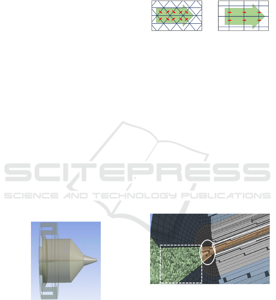
3.3 Meshing
The result of a CFD simulation depends not only on
how dense the mesh is in the area of large velocity
gradients (e.g. on the walls) but also on the type of
elements and symmetries in the meshes (see Fig. 3).
Interfaces that are not perpendicular to the largest
mass flows (Fig.3, left) enhance numerical diffusion.
Figure 3: Mass flow in different meshes. Physical flow
direction through the model (green) and flow through the
interfaces of the elements (red).
Particularly critical areas with respect to meshing
are the nozzle and the free jet. In the conical region of
the nozzle, the element size decreases with the nozzle
diameter. Thus, the mass flow through successive
elements remains approximately the same, which
reduces numerical diffusion. In this case, usage of a
tetrahedral mesh is appropriate (see Fig. 4, left,
dashed frame). In the transition zone between nozzle
and free jet at the tip of the nozzle, a transfer from
tetrahedral elements to hexahedral elements is
implemented (see Fig. 4, center, solid ellipse).
A free jet does not always have a unique,
mathematically stable solution, so numerical
diffusion must be minimised to improve convergence.
This is achieved by selecting the mesh in such a way
that the boundary surfaces of the elements are as
perpendicular as possible to the largest mass flows
(see Fig. 4, right, solid frame). This would not be the
case for elements in tetrahedral form or asymmetric
meshes. Here the generation of asymmetric solutions
due to numerical diffusion are more likely.
Figure 4: Section through the mesh used; decreasing
element size in the area of the nozzle (left, dashed frame),
symmetrical meshing in the area of the free jet (right, solid
frame) and transition zone (middle, solid ellipse).
In turbulent flows, special attention must be paid
to the boundary conditions at the walls, since different
layers form here. The transition from the fully
turbulent to the wall can be divided into three layers:
the purely viscous bottom layer, the transition layer
and the overlap layer (Schlichting and Gersten 2006).
Modelling and Simulation of an Aerosol-on-Demand Print Head with Computational Fluid Dynamics
47

The k-𝜔-𝑆𝑆𝑇-model used also models the boundary
layers and requires a much finer meshing at the wall.
Comparability of the boundary layers in different
flows is achieved by the de-dimensioned wall
distance (Eq. 5).
𝑦
= 𝜌𝑢
𝑦
𝜇
(5)
with 𝑢
=
.
Here ρ denotes the density, u
τ
the shear stress rate,
µ the viscosity, and τ the shear stress in that layer.
The required resolution of the meshing thus depends
on both the choice of turbulence model and the
velocity gradients due to the de-dimensioned wall
spacing (Ansys 2021). This means that for the same
geometry and different flow velocities, different
densities of meshing must be chosen.
In our model, the wall layers are meshed at a very
fine resolution, so that the first mesh element is in the
range 𝑦+ ≈ 1. Thus, the influences of the purely
viscous sublayer are fully represented (Ansys 2021).
This resolution is achieved by using prism elements
in this layers.
Furthermore, since the Euler-Lagrange model
used involves a particle-related consideration of the
discrete phase, it must be ensured that in principle a
particle can be located completely within a mesh
element. Therefore, care must be taken that the
minimum size of the mesh elements is chosen in a
way that it reaches a multiple of the particle size. The
mesh consists of 4,107,235 elements with 1,097,103
nodes and a minimum edge length of 60 µm.
Generation of the prism layers is conducted with a
transition rate of 0.272 and a growth rate of 1.2.
4 SIMULATION
The simulation is carried out on a workstation. The
processor used is the AMD Ryzen Threadripper
3970X with 32 cores, 64 threads at 3.7 GHz, 128 GB
RAM and an Nvidia Titan RTX graphics processor
with 24 GB.
4.1 Modelling of Ink and Sheath Gas
The ink is modelled as distilled water so that the
discrete phase consists of atomised droplets.
Replacing the functional ink with distilled water in
the model is permissible because aerodynamic
focusing does not depend on the dynamic viscosity of
the ink or the particle content in the ink. Hence, once
the simulative functional proof of aerodynamic
focusing has been provided, it is basically possible for
all liquids that can be atomised in the capillary. If the
droplets of functional inks have a different
momentum than the droplets of distilled water due to
their density or diameter, the sheath gas mass flow
can be adjusted in such a way that focusing of the
aerosol jet is achieved.
The droplets make up only a small volume
fraction in the mixing chamber (< 10 % of the total
volume), thus the particle-particle interaction of the
droplets can be neglected. However, a coupling of the
discrete phase with the continuous phase is
established so that a momentum transfer of the
aerosol to the sheath gas, which is not negligible for
large aerosol mass flows, is taken into account. Table
3 shows the simulation parameter of the aerosol at the
outlet of the capillary (Zeltner 2020).
Table 3: Simulation parameters of the aerosol at the outlet
of the capillary.
Parameter Value
max. exit angle [°]
max. diameter of droplets [µm]
max. exit velocity [m/s]
max. aerosol mass flow [kg/s]
25
20
10
1.21 ⋅ 10
-5
The sheath gas is the continuous phase in the
Discrete Phase Model. As sheath gas Argon is
modelled as an ideal gas. The parameters are dipicted
in Table 4.
Table 4: Modelled properties of Argon.
Parameter Value
Specific heat [J/(kg K)]
Thermal conductivity [W/(m K)]
Viscosity [kg/(m s)]
Molecular weight [kg/kmol]
520.64
0.0158
2.125 ⋅ 10
-5
39.948
4.2 Determination of the Operating
Point
Based on the modelling of the entire print head,
simulations of the printing process are carried out. In
the first step, the operating points are determined at
which the aerosol can be focused by means of the
sheath gas without contact with the wall. To
determine these working points, the mass flow of the
sheath gas is changed step by step for varying mass
flows of the aerosol until no contact of the aerosol
with the nozzle walls occurs.
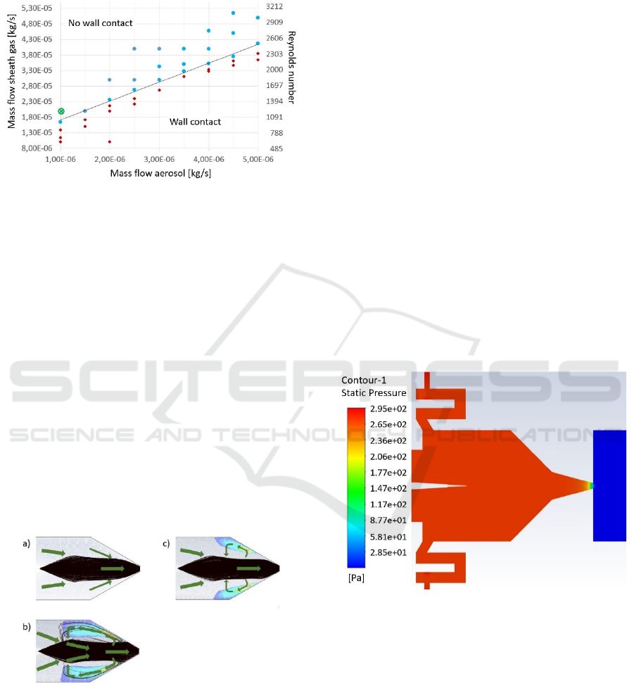
Figure 5 shows the relationship between sheath
gas mass flow, aerosol mass flow, and wall contact.
The red diamonds depict mass flow combinations
resulting in a wall contact, while blue dots denote
mass flow combinations without wall contact. The
SIMULTECH 2022 - 12th International Conference on Simulation and Modeling Methodologies, Technologies and Applications
48
region of operation without wall contact can be
separated by a straight line from the region with wall
contact.
Figure 5: Relationship between sheath gas mass flow and
aerosol mass flow. Blue dots: no wall contact; red
diamonds: wall contact; green encircled cross: chosen
operating point.
Since the Reynolds number is linearly dependent
on the sheath gas mass flow, it is also possible to
directly infer the Reynolds number for the process
window. With the help of the diagram in Fig. 5, it is
possible to determine a maximum aerosol mass flow
at a specified sheath gas mass flow. For proper
operation of the nozzle, a laminar flow of the ink is
required. The operating point of the nozzle is
therefore selected to achieve a low Reynolds number
to allow for laminar flow. Hence, an operating point
at a Reynolds number of Re = 1200 is chosen for the
further simulations, which corresponds to a sheath
gas mass flow of 2 ⋅ 10
-5
kg/s. If the momentum of the
aerosol mass flow is too large, eddies will form due
to mass conservation, which will deflect some of the
droplets towards the nozzle wall (Fig. 6 b).
Figure 6: Eddy generation in the nozzle at Re = 1200 and
increasing aerosol mass flow. Droplet tracks (black) and
flow of the sheath gas (green). a): no wall contact, aerosol
mass flow 1 ⋅ 10
-6
kg/s; b): light wall contact, aerosol mass
flow 2 ⋅ 10
-6
kg/s; c): strong wall contact, aerosol mass flow
5 ⋅ 10
-6
kg/s.
Furthermore, if the aerosol mass flow is too large,
the aerosol cannot be deflected sufficiently towards
the axis of symmetry, so that wetting of the nozzle
walls occurs (Fig. 6 c). If the mass flows are in the
range above the straight line of Fig. 5, no eddies form
and the aerodynamic focusing is large enough to
prevent wetting of the nozzle walls (Fig. 6 a). Hence,
the operating point is specified with a sheath gas mass
flow of 2 ⋅ 10
-5
kg/s (Re = 1200) and an aerosol mass
flow of 1 ⋅ 10
-6
kg/s (marked by the green encircled
cross in Fig. 5) to ensure an operating point with no
wall contact.
4.3 Steady-state and Transient
Considerations
As the operating point of the print head has been
determined, the functionality of the printing process
can be examined. The free jet is included in the
investigations, as the focusing of the jet outside the
nozzle is to be examined. At the boundary of the
control space, a constant pressure to the environment
is set as a boundary condition. Inflow and outflow is
allowed for all modeled phases (pressure outlet).
Figure 7 shows the static pressure distribution for the
model used.
Figure 7: Static pressure.
In order to deliver reproducible results, a time-
independent, i.e. steady, behaviour of the printing
process is necessary. Therefore, steady-state
simulations are carried out first. The settings listed in
Tables 3 and 4 are used for this purpose. Results of
the steady-state simulations at the operating point are
a focussed aerosol jet with a diameter of approx. 0.8
mm when leaving the nozzle and approx. 0.15 mm at
the focal point, located at a distance of 4.2 mm from
the nozzle (Fig. 8 b). In the nozzle no wall contact
occurs and the flows are rotationally symmetrical.
Modelling and Simulation of an Aerosol-on-Demand Print Head with Computational Fluid Dynamics
49
Hence, in steady-state, the proper functioning of the
AoD print head is validated by simulation.
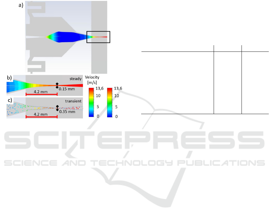
Time-resolved transient simulations are also
performed to investigate whether truly stable steady-
state solutions are present or whether they are merely
averages of a transient solution.
Figure 8: Simulation of the droplet tracks for the entire
system. The rectangular region in a) is the region of interest.
b) steady-state simulation, c) transient simulation.
Due to the transient observation, another particle
model has to be used, which is called unsteady
particle tracking in Ansys Fluent. In this particle
model, individual droplets have a position and a
velocity in every time step. No continuous trajectories
are calculated, but only the position of the droplets is
updated. The number of newly generated droplets per
time step is set to 20 to limit the computational effort.
A very fine time increment is necessary for the
droplets after they leave the capillary. The fine time
increment leads to extremely slow movements of the
droplets elsewhere in the model, so that in the
simulation over 1000 time increments are necessary
until a steady aerosol flow reaches the substrate. This
makes the time-resolved simulations very
computationally intensive. The required time
increment for the droplets was set at 0.1 ms per
increment. The total simulated time span is approx.
0.5 s.
The time-resolved simulations give similar results
to the steady-state simulations (see Fig. 8 c). Again,
no wall contact occurs in the nozzle. The position of
the focal point and the velocities of the droplets are
identical in both approaches (see Fig. 8 and Table 5).
However, the diameter of the focal point is larger
in the transient simulations than in the steady-state
simulations. A deflection or defocusing of the aerosol
jet due to turbulence in the free jet is neither observed
in the steady-state nor in the time-resolved
simulations.
As a result, it can be stated that steady-state
solutions form at the free jet. These results confirm
the assumption of a steady-state behaviour, which is
of existential importance for functional printing.
Thus, all requirements for AoD-printing are
fulfilled and the newly developed concept has been
validated by simulation.
Table 5: Properties of steady and transient simulations.
5 CONCLUSIONS
In this article we present the proof-of-concept of a
new principle of an aerosol jet-on-demand print head
for functional printing by means of CFD simulations.
Aerodynamic focusing of the aerosol jet is based on
properly adjusting the mass flows of the sheath gas
and the aerosol and the appropriate design of the
outlet nozzle. Design considerations are made with
respect to generation of a homogenised sheath gas
flow and the manufacturing processes available at our
institute, thus resulting in a design-for-manufacturing
approach. Modelling and meshing of the print head is
discussed for the critical areas to avoid numerical
diffusion and to improve the convergence.
Simulation of the operation of the print head is
done by modelling the functional ink as distilled
water. Since aerodynamic focusing is independent of
the dynamic viscosity of the fluid or the particle
content in the fluid, this approach is permissible. In
principle, aerodynamic focusing of all fluids that can
be atomised in the capillary is possible. If, due to
density or diameter, the droplets of functional inks
have a different momentum than the droplets of
distilled water, the mass flows of the sheath gas and
the aerosol have to be adjusted to achieve focusing of
the aerosol jet.
There are two conditions which must be met for
reliable function of the aerosol jet-on-demand print
Pro
p
ert
y
stead
y
transient
Reynolds number
max. velocity sheath gas
max. velocity droplets
velocity droplets @ nozzle exit
Diameter aerosol jet @ nozzle
exit
Diameter aerosol jet @ focus
focus position
1200
18.3 m/s
13.6 m/s
7 m/s
0.8 mm
0.15 mm
4.2 m
m
1200
18.3 m/s
13.6 m/s
7 m/s
0.9 mm
0.35 mm
4.2 m
m
SIMULTECH 2022 - 12th International Conference on Simulation and Modeling Methodologies, Technologies and Applications
50

head. These are on the one hand the generation of a
stable and focused aerosol beam, and on the other
hand the prevention of wetting of the inner nozzle
wall by the aerosol. The fundamental operating
parameters ensuring these conditions are found by
CFD simulations. In a first step the relationship
between the mass flows of the sheath gas and the
aerosol and the wetting of the inner wall is
investigated leading to an operating point at
Re = 1200 ensuring a non-wetting condition. Since a
time-continous operation of the print head is a
prerequisite of a reliable function of aerosol-on-
demand printing, steady-state as well as transient
simulations are performed to investigate for time
dependency of the solutions. The transient
simulations give identical results as the steady-state
simulations concerning the position of the beam focus
as well as the velocity distribution. Thus, all
requirements for aerosol-on-demand printing are
fulfilled and the newly developed concept has been
validated by simulation.
In future studies, the simulative findings will be
experimentally evaluated and validated by realising
the design-for-manufacture as experimental setup.
REFERENCES
Ansys 2021. Ansys Fluent User’s Guide, Release 2021 R2,
ANSYS, Inc. Canonsburg, PA, USA
Chang, J.S., A.F. Facchetti, and R. Reuss. 2017. A circuits
and systems perspective of organic/printed electronics:
Review, challenges, and contemporary and emerging
design approaches. IEEE Journal on emerging and
selected topics in circuits and systems 7, : 1–21. doi:
10.1109/JETCAS.2017.2673863.
Ganz, S., H.M. Sauer, S. Weißenseel, J. Zembron, R. Tone,
E. Dörsam, M. Schaefer, M. Schulz-Ruthenberg. 2016.
Printing and Processing Techniques. Nisato, G., Lupo,
D., and Ganz, S. (editors): Organic and Printed
Electronics: Fundamentals and Applications: 48-116.
Singapore: Pan Stanford Publishing.
Gupta, A.A., A. Bolduc, S. G. Cloutier and R. Izquierdo.
2016. Aerosol Jet Printing for printed electronics rapid
prototyping, IEEE International Symposium on
Circuits and Systems (ISCAS), Montreal, QC: 866-869,
doi: 10.1109/ISCAS.2016.7527378.
Guha, A. and Smiley, B. 2010. Experiment and analysis for
an improved design of the inlet and nozzle in Tesla disc
turbines. Proceedings of The Institution of Mechanical
Engineers Part A-journal of Power and Energy - PROC
INST MECH ENG A-J POWER 224. doi:
10.1243/09576509JPE818.
Hedges, M. and A. B. Marin. 3D Aerosol Jet Printing -
Adding Electronics Functionality to RP/RM. Direct
Digital Manufacturing Conference (Berlin) 2012. url:
https://optomec.com/wp- content/uploads/2014/04/Opt
omec_NEOTECH_ DDMC_3D_Aerosol_Jet_Printing
.pdf. (accessed: 24.02.2020).
Magdassi, S. 2010. The Chemistry of Inkjet Inks. Singapore:
World Scientific Publishing.
Menter, F.R. 1994. Two-Equation Eddy-Viscosity
Turbulence Models for Engineering Applications.
AIAA Journal. 32(8): 1598–1605.
Mette, A., P. L. Richter, M. Hörteis, S. W. Glunz. 2007.
Metal Aerosol Jet Printing for Solar Cell Metallization,
Progress in Photovoltaics 15, 621–627. doi:
10.1002/pip.759.
Neotech. 2021. 3D Printed Electronics applications realised
by Neotech AMT. url: https://neotech-amt.com/
applications. (accessed: 19.10.2021).
Schlichting, H. and K. Gersten. 2006. Grenzschichttheorie.
10. Auflage. Berlin, Heidelberg: Springer. doi:
10.1007/3-540-32985-4.
Sieber, I. R. Thelen, and U. Gengenbach. 2020. Assessment
of high-resolution 3D printed optics for the use case of
rotation optics. Opt. Express 28: 13423-13431.
Sieber, I., R. Thelen, and U. Gengenbach. 2021.
Enhancement of High-Resolution 3D Inkjet-printing of
Optical Freeform Surfaces Using Digital Twins.
Micromachines 12(1): 35. https://doi.org/10.3390/mi1
2010035.
Sieber, I., Zeltner, D., Ungerer, M., Wenka, A., Walter, T.,
Gengenbach, U. (2022). Design and experimental setup
of a new concept of an aerosol-on-demand print head.
Aerosol Science and Technology. Taylor & Francis.
DOI: 10.1080/02786826.2021.2022094
Sirringhaus, H. and T. Shimoda. 2003. Inkjet Printing of
Functional Materials. MRS Bulletin 28(11): 802–806.
doi: 10.1557/mrs2003.228.
Wilcox, D.C. 2006. Turbulenc Modelling for CFD, 3rd
edition). La Canada, California: DCW Industries, Inc.
Ungerer, M., A. Hofmann, R. Scharnowell, U. Gengenbach,
I. Sieber, and A. Wenka. 2018. Druckkopf und
Druckverfahren [Print head and printing method].
Patent: DE 10 2018 103 049.5.
Ungerer, M. 2020. Neue Methodik zur Optimierung von
Druckverfahren fur die Herstellung funktionaler
Mikrostrukturen und hybrider elektronischer
Schaltungen [New methodology for optimising printing
processes for the production of functional
microstructures and hybrid electronic circuits].
Dissertation, Karlsruhe, Germany: Karlsruhe Institute
of Technology (KIT).
Zeltner, D. 2020. Auslegung und Evaluierung einer
Dosiereinheit zur additive Fertigung funktionaler
Strukturen [Design and evaluation of a dispensing unit
for additive manufacturing of functional structures].
Karlsruhe: Karlsruhe Institute of Technology, Institute
for Automation and Applied Informatics.
Modelling and Simulation of an Aerosol-on-Demand Print Head with Computational Fluid Dynamics
51
