
Mechanical Design of an Assistive Robotic System for Bilateral Elbow
Tendinopathy Rehabilitation
Andres Guatibonza
a
, Carlos Zabala, Leonardo Solaque
b
, Alexandra Velasco
c
and Lina Pe
˜
nuela
d
Militar Nueva Granada University, Bogot
´
a, Colombia
Keywords:
Rehabilitation Robotics, Upper Limb, Mechanical Design, Design Criteria.
Abstract:
Diseases related to upper limb mobility are increasingly common among the actual population. For this reason,
robotic physical assistive systems have been proposed to support therapy processes and improve the functional
capabilities of people. However, there are still open issues related to mechanical design, such as joint coupling
and bidirectional configurations. In this work, we present a novel design of a 7 DoF robotic assistive system
with anthropometric adjustment, arm change configuration for elbow tendinopathies rehabilitation to use it
in both arms. The design is supported by the analysis of the upper limb pathophysiology and the exercises
required to treat elbow tendinopathies.
1 INTRODUCTION
Currently, physical disabilities are a public health
problem, affecting people’s quality of life and lim-
iting the development of physical activities (Jabeen
et al., 2016). According to the World Health Organi-
zation (WHO), more than one billion people world-
wide have a disability, of which 16.5% suffer from
mobility-related impairments (WHO, 2011). Some
of the causes of this kind of impairments are injuries
related with neurological, vascular, infectious or de-
generative agents. Moreover the impairments can be
caused by high level of demand in the performance
of repetitive activities, occupational or domestic ac-
cidents, etc. (Jabeen et al., 2016; Dick et al., 2010;
Fagher and Lexell, 2014). These injuries usually oc-
cur in the tendon structures of the upper limb, espe-
cially in the shoulder and elbow becoming into ten-
dinitis or tendinopathies (Occhionero et al., 2014;
Costa et al., 2015), which consequently results in
pain, difficulty in the mobility and low strength. In
these cases, a physical rehabilitation process is re-
quired to restore the functionality of the affected joint
(Ritchie, 2003; Hillman, 2012; Kessler, 1950; ACP,
1932). Patients undergo treatments that include ex-
a
https://orcid.org/0000-0001-6102-563X
b
https://orcid.org/0000-0002-2773-1028
c
https://orcid.org/0000-0001-7786-880X
d
https://orcid.org/0000-0002-1925-9296
posing muscle tissues to progressive stress, increas-
ing range of motion and muscle strength, and prevent-
ing the onset of chronic pain (Ritchie, 2003; McHugh
et al., 2013; Wattchow et al., 2018; Bruder et al.,
2017; Milicin and S
ˆ
ırbu, 2018; Contributors, 2003;
Gates et al., 2015). As part of the rehabilitation pro-
cess, assistive robotics can be used to support phys-
iotherapy, providing technological tools to assist an
appropriate intervention depending on the level of
impairment (Linda et al., 2018; Olanrewaju et al.,
2015). The use of these technologies has increased
due to the ease of quantifying assessment variables
such as range of motion, velocities, muscle activity
and strength (Ballantyne and Rea, 2019). However,
the development of robotic devices naturally involves
mechanical design to a large extent, which is the focus
of our work.
Assistive systems are designed according to the
biomechanical characteristics of the required joint.
From the anatomical viewpoint, in exoeskeletons it
is complex to design a system that shares perfect
coupling with the joint preserving the range of mo-
tion. The limitation remains in the loss of mobility
ranges, usually to avoid the collision of the robotic
system with the patient; for example, when shoul-
der adduction-abduction exercises are performed (Is-
lam et al., 2020; Zimmermann et al., 2019).. In
the literature, there are some works that seek to im-
prove the conditions of mechanical coupling, such as
(Lessard et al., 2018) where tensegrity is proposed
320
Guatibonza, A., Zabala, C., Solaque, L., Velasco, A. and Peñuela, L.
Mechanical Design of an Assistive Robotic System for Bilateral Elbow Tendinopathy Rehabilitation.
DOI: 10.5220/0011289800003271
In Proceedings of the 19th International Conference on Informatics in Control, Automation and Robotics (ICINCO 2022), pages 320-329
ISBN: 978-989-758-585-2; ISSN: 2184-2809
Copyright
c
2022 by SCITEPRESS – Science and Technology Publications, Lda. All rights reserved

to approximate real movements more accurately, or
in (Liu et al., 2018) where mechanical postural syn-
ergies are developed to reduce complexity of trans-
mission mechanisms. In addition, in (Zimmermann
et al., 2019) the exoskeleton ANYexo has been devel-
oped, where the range of motion (ROM) is optimized
to mimic the interaction of the specialist. Another
example is the system TTI-Exo designed by (Ugurlu
et al., 2015), which has adjustable link lengths to par-
tially align the human and exoskeletal joints to avoid
uncontrolled forces caused by hyperstaticity.
On the other hand, systems have been designed
bilaterally or with an option to switch arms. For end-
effector based systems, bilateral design and imple-
mentation is much simpler because the anchor point
between the system and the upper limb is usually
through the hand grip. Work such as (Miao et al.,
2018; Miao et al., 2020a; Miao et al., 2020b; Sheng
et al., 2019; Zhang et al., 2020; Sun et al., 2021) have
implemented bilateral training in end-effector based
systems. For the case of exoskeletons the design is
more complex, and some authors opt to duplicate the
robotic system by adapting it for the opposing limb
as (Ugurlu et al., 2015; Kumar et al., 2019). Alterna-
tively, the same system for one limb can be adapted
for the opposite limb by means of an arm-switching
configuration. However, it reduces costs and adds at-
tributes in terms of adaptability, especially if used in
physical rehabilitation applications. The best known
system with this configuration is the Armeo Power
system by Hocoma (HOCOMA, ; Wu et al., 2018).
Nevertheless, to the best of our knowledge, in the lit-
erature there are no designs with this quality apart
from the Armeo Power.
In this paper we propose a mechanical design of
an assistive robotic system of 7 degrees of freedom
to support the therapy of elbow tendinopathies. The
criteria of a medical specialist has been considered as
part of the formulation and the development of the
mechanical design, as suggested by (Cruz Mart
´
ınez
et al., 2020). We present a novel design of anthropo-
metric adjustment and arm change, avoiding the need
to duplicate the arm. For this, initially we perform
an analysis of the physiopathology of the upper limb,
from this, qualitative and quantitative design criteria
are defined, determining the degrees of freedom and
torques required according to specifications obtained
from these criteria. Subsequently, we develop the me-
chanical design, showing the preliminary version to-
gether with the arm-switching configuration; then, we
present some conclusions of this work.
2 PHYSIOLOGY,
BIOMECHANICS AND
PATHOLOGIES OF THE UPPER
LIMB
In this section, we analyze concepts related to the
anatomy, physiology, pathologies and physiotherapy
of the upper limb. It is mandatory to know how the
articular system of the upper limb works in order to
understand the biomechanics and subsequently de-
velop a mechanical analogy that will allow us to es-
tablish design criteria according to the problem to be
addressed.
The upper limb is composed of three parts: the
arm, the forearm and the hand. In the proximal part
of the arm is the joint complex called the shoulder
(Fierro, 2015), which is the most mobile joint in the
entire human body since it allows the orientation of
the upper limb in the three anatomical planes (sagit-
tal, frontal and transverse), which allows flexion-
extension, adduction-abduction, internal-external ro-
tation, horizontal flexion-extension and complemen-
tary movements such as protraction-retraction (Keith
L. Moore and Agur, 2013; Knudson, 2007). The
elbow is located in the distal part of the arm and
proximal part of the forearm (Palacios, 2015). This
joint allows flexion and extension movements, as
well as distributing the load bearing forces and trans-
mitting pronation and supination movements to the
wrist. In the proximal part of the hand we find the
wrist joint, which allows movements of pronation-
supination, flexion-extension and radial-ulnar devia-
tion (Fierro, 2015; Keith L. Moore and Agur, 2013).
Note that in the schemes of elbow therapy exercises,
it also involves the mobility of the other joints of the
upper limb. (Knudson, 2007; Taboadela, 2007; Chau-
rand et al., 2007)
The normal joint ranges are shown in the Table
1, where the measurement methods of the AAOS
(American Academy of Orthopaedic Surgeons) of the
United States are used.
2.1 Tendinopathies and Physiotherapy
The elbow joint is frequently exposed to different con-
ditions or pathologies. Among the most common are
traumas such as fractures, dislocations, simple contu-
sions, sprains and strains (Med, ). There are also el-
bow tendinopathies produced mainly by activities or
work that require constant and repetitive use of the el-
bow (Ruiz, 2011). The tendinopathies of the elbow
are divided into lateral epicondylitis (tennis elbow)
(Sanchez, ), and medial epicondylitis (golfer’s elbow)
Mechanical Design of an Assistive Robotic System for Bilateral Elbow Tendinopathy Rehabilitation
321
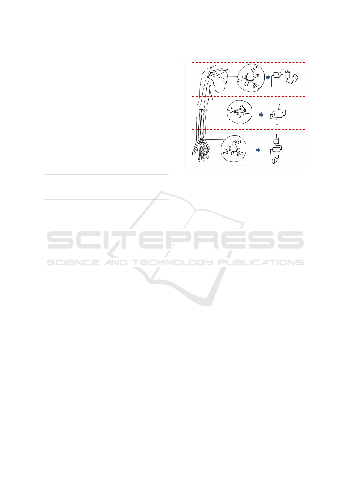
Table 1: Joints and ranges of mobility. AAOS: American
Academy of Orthopaedic Surgeons.
Joint Movement Angles
Shoulder
girdle
Protraction -
Retraction
Protraction:
0° − 25°/30°, Re-
traction: 0° − 25°/30°
Shoulder
(gleno-
humeral)
Abduction -
Adduction
Abduction: 0° − 180°,
Adduction: 0°
Flexion -
Extension
Flexion: 0° − 180°, Ex-
tension: 0° − 60°
Internal -
External
rotation
Internal: 0° − 70°, Exter-
nal: 0° − 90°
Horizontal
Flexion -
Extension
Flexion: 0° − 135°, Ex-
tension: 0° − 40°/50°
Elbow Flexion -
Extension
Flexion: 0° − 150°, Ex-
tension: 0°
Wrist Pronation -
Supination
Supination: 0° − 80°,
Pronation: 0° − 80°
Flexion -
Extension
Flexion: 0° − 80°, Exten-
sion: 0° − 70°
(Grupo, 2011; SportMe, ). In these cases of trauma,
a physical rehabilitation process is necessary to re-
store the person physically, socially and occupation-
ally (ACP, 1932; Kessler, 1950; Ritchie, 2003; Hill-
man, 2012).
The main goal of physical rehabilitation is the
prevention of stiffness and restoration of the joint.
Once mobility, stability and pain are controlled, speed
and strength are restored later, essentially to prevent
chronic pain (Vulliet et al., 2017). Within physi-
cal therapy, the specialist uses some tests to validate
the diagnosis of tendinopathy as Maudsley, Mills,
Cozen, inverted cozen, golfer’s elbow sign, etc. And
then uses other exercises for rehabilitation as stretch-
ing, mobility and isometric exercises (Kessler, 1950;
ACP, 1932; Henning, 2010). As mentioned before,
the exercise schemes used in the diagnosis and re-
habilitation of tendinopathies require the use of the
elbow joint, and also the shoulder and wrist joints
(Cort
´
es Rojas and Ramos Moreno, 2017). Therefore,
the mechanical design must respond to the minimum
specifications of movement of the joints included in
the different diagnostic and rehabilitation protocols.
This leads to the selection of joints, ranges of mobil-
ity and degrees of freedom in the design of the robotic
system.
3 DESIGN CRITERIA
Based on the anatomy, physiology, and biomechanics
of the upper limb, and considering the diagnostic and
Figure 1: Anatomical-Mechanical analogy.
rehabilitation exercises for elbow tendinopathies, the
anatomical-mechanical model and the design specifi-
cations of the assistive system are determined. The
starting point is an anatomical and functional para-
metric definition of the upper limb. Then, a first
approach is made to design the device based on the
biomechanics of the upper limb. In Fig. 1 an analogy
of the mechanical model approach is presented.
Anatomically, it is complex to design an active
system that shares a perfect coupling with the joint
and preserves maximum working space, and the sys-
tem design must guarantee a perfect coupling between
the robotic system and the human limbs in order to
avoid discomfort or collisions (Islam et al., 2020;
Zimmermann et al., 2019), but preserving to a greater
extent the ranges of mobility.
3.1 Qualitative and Quantitative
Criteria
An qualitative and quantitative criteria are established
by analyzing the advantages and disadvantages of pa-
rameters such as the type of device (exoskeleton, end-
effector), type of chain (open, closed), type of trans-
mission (rigid, elastic), and above all, to seek the
greatest inclusion of the population through a para-
metric analysis of anthropometry based on anthro-
pometric indices of the Latino and U.S. population
(Avila-Chaurand et al., 2007; Gordon et al., 1989).
In Table 2 the criteria considered in the design of the
robotic assistive system are shown where qualitative
criteria as type of device, type of chain, type of trans-
mission, and quantitative criteria as dimensional pa-
rameters and functional parameters are considered.
The first three aspects listed in Table 2 (type of
ICINCO 2022 - 19th International Conference on Informatics in Control, Automation and Robotics
322

Table 2: Qualitative and quantitative design criteria.
Advantages Disadvantages
Type of device
Final effector
Does not depend on the length of
the human arm, more people inclu-
sion
Limited movement according to di-
mensions
Easy to manufacture Cannot move each joint independently
Joint position estimation needed, can
not be directly measured
Exoskeleton
The movement occurs directly in
the patient’s joints.
Depends on anatomical lengths of pa-
tients, exclusion criteria
Independent movement for each
joint
Increased manufacturing complexity
Independent control of each junc-
tion, independent measurements
Type of chain
Open Wide movement regardless of de-
vice dimensions
Increased susceptibility to external
forces and inertia
Closed Major stability against external
forces
Movement limited by the dimensions
of the device
Type of transmission
Rigid
Direct connection with drive shaft,
avoids losses for friction or elastic-
ity.
Possible fractures in the structure due
to unforeseen shocks
Space optimization
Elastic
Quieter movements Possible sliding under forces greater
than supported
Absorbs shocks in the transmission Large dimensions
Easy disengagement and mainte-
nance
Min Max
Dimensional parameters
Height 1.47 m 1.93 m
Body mass 46.7 Kg 124.7 Kg
Upper limb
weight
2.335 Kg 6.235 Kg
Arm length 0.27 m 0.41 m
Arm perimeter 0.23 m 0.34 m
Forearm length 0.21 m 0.33 m
Forearm
perimeter
0.21 m
Side arm length 0.65 m 0.82 m
Elbow width 0.055 m 0.074 m
Elbow to elbow
width
0.34 m 0.7 m
Hand length 0.15 m 0.19 m
Wrist width 0.045 m 0.06 m
Hand width 0.069 m 0.091 m
Joint and
movement
Approx. torque + standard devi-
ation (N) in women
Approx. torque + standard devia-
tion (N) in male
Functional parameters
Shoulder ad-
duction
28.4 ± 7.5 51.3 ± 17.7
Shoulder flex-
ion
30.4 ± 8.7 55.0 ± 17.6
Shoulder exten-
sion
34.3 ± 11.2 73.5 ± 27.9
Shoulder inter-
nal rotation
19.4 ± 4.6 41.1 ± 10.1
Shoulder exter-
nal rotation
20.7 ± 5.2 38.3 ± 9.1
Elbow flexion 39.4 ± 7.7 70.9 ± 15.9
Elbow exten-
sion
22.0 ± 4.7 44.3 ± 9.8
Hand grip 250.4 ± 54.8 411.3 ± 73.5
Mechanical Design of an Assistive Robotic System for Bilateral Elbow Tendinopathy Rehabilitation
323

device, type of chain and type of transmission) are
based on the number of advantages versus the num-
ber of disadvantages. The other criteria are delimited
specifications according to the application. First, for
the type of device an exoskeleton is more appropriate,
the most important reason is that the motion is applied
directly at the joint and reduces the need to estimate
positions and velocities. Second, for the type of chain
is indifferent if design specifications and workspaces
are retained. In our case, an open chain configuration
was chosen because of the design complexity of the
whole upper limb, and also, the selection of a closed
chain limits the range of joint amplitude and singu-
larities may appear (Romero-Acevedo et al., 2018;
Guatibonza et al., 2018). Third, the type of transmis-
sion also depends on the application and the amount
of stress that will be applied to the actuator and to the
mechanical structure. In our case, the motion stud-
ies and the technical characteristics of the actuators
define the necessary load to satisfy the requirement
torque. Finally, the dimensional parameters define to
a large extent the design specifications of the robotic
system, since they are based on anthropometric stud-
ies of the target population. These dimensional cri-
teria have maximum and minimum values that the
robotic system must achieve. This is an aspect of
adaptability and generalization within the framework
of the target population. Similarly, the functional pa-
rameters define the specifications in terms of maxi-
mum torques and the need of transmission systems.
Whether using them or not depends on the technical
characteristics of the motors and the effort require-
ments.
In this work, the option of bilateral handling with-
out the need to duplicate the robotic system for the
opposite arm is proposed. This is possible through
an arm switching configuration. This feature reduces
costs and adds attributes in adaptability, especially if
it is used in physical rehabilitation applications (HO-
COMA, ; Wu et al., 2018).
3.2 Degrees of Freedom
Based on the mobility ranges defined in Table 1, the
workspace of the entire upper limb is defined by iden-
tifying the maximum lenghts that the upper limb can
achieve in the frontal, transverse and sagittal planes.
The design of the robotic system must then be ad-
justed to the defined workspace. The challenge now
is to define a design that preserves spatial specifi-
cations, adaptability to people with different anthro-
pometric proportions, collision avoidance with the
robotic system and configuration for arm-switching.
The following aspects play a very important role in
the design to guarantee the working space: 1. Num-
ber of degrees of freedom, 2. Optimization of the
space in the design constrained by the type of ac-
tuator used, and 3. The order in the location of
each of the actuation axes. The validation of points
1 and 3 requires heuristic strategies that can be ob-
tained by means of physical scale models or simu-
lation models. In our case, we verified this strategy
using both methods, focused mainly on the elbow
joint, because it is a compound joint where several
movements are generated on the same point (flexion-
extension, adduction-abduction, flexion-horizontal
extension, internal-external rotation and protraction-
retraction (scapulohumeral)) (Keith L. Moore and
Agur, 2013; Knudson, 2007).
The design of the system suggests a minimum
of 6 degrees of freedom (DoF), since the exercise
schemes defined in both diagnosis and rehabilitation
of tendinopathies indicate not only the use of the el-
bow joint, but also the other joints of the upper limb.
In our case, we consider the protraction-retraction
movements as a complement of the flexion-extension
horizontal shoulder movements to reach the full range
of amplitude in the transverse plane. Consequently,
the design is oriented to a redundant 7 DoF robotic
system. The procedure is as follows: We start from
a conceptual design where an initial order of the axes
of actuation is defined. Subsequently, we transfer the
concept to a physical scale model so that the options
of the order and alignment of the axes with the shoul-
der can be visually analyzed. Finally, the configu-
ration on the scale model suggests an organization
of the axes of action as defined here: 1. protraction
- retraction (scapulo-humeral), 2. flexion - horizon-
tal extension (gleno-humeral), 3. flexion - extension
(gleno-humeral), 4. adduction - abduction (gleno-
humeral), 5. elbow flexion - extension, 6. wrist prona-
tion - supination, and 7. wrist flexion - extension.
With these configurations, a simple CAD model is
constructed to confirm the range of the system in the
previously described workspace.
In Fig. 2 a simple conceptual design of the 7
DoF system is shown in the limit positions of the
workspace. The proposed configuration satisfies the
workspace of the upper limb and no collisions are
generated in maximum amplitudes of the movements
such as abduction, extension and horizontal flexion of
the shoulder.
3.3 Motion Analysis
The motion analysis allow to determine the maximum
torque required for each joint. In shoulder joint, ac-
tuators must provide necessary torque to move both
ICINCO 2022 - 19th International Conference on Informatics in Control, Automation and Robotics
324
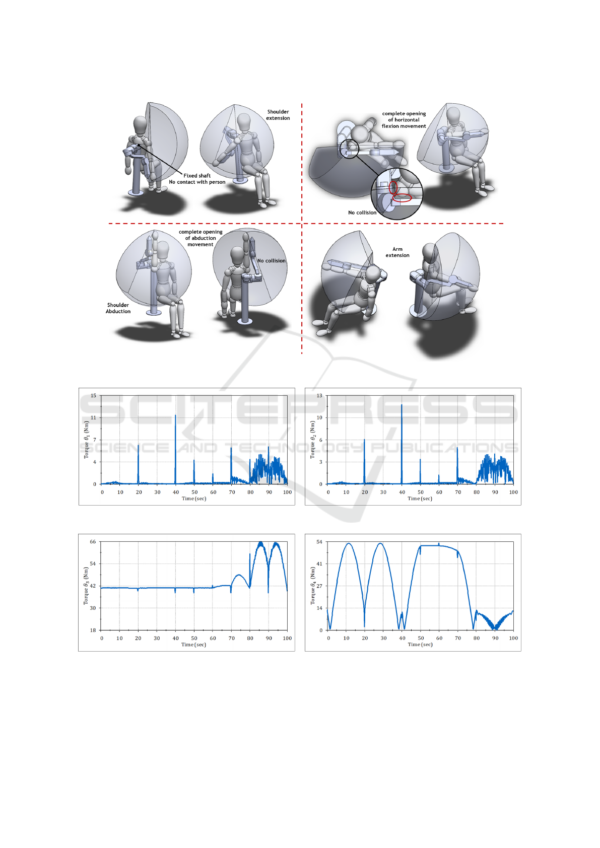
Figure 2: Composition of upper limb workspace based in AAOS.
(a) Torque acquisition from pronation-supination move-
ments.
(b) Torque acquisition from horizontal flexion-extension
movements
(c) Torque acquisition from flexion-extension movements (d) Torque acquisition from abduction-adduction move-
ments
Figure 3: Theoretical torques from motion analysis.
Mechanical Design of an Assistive Robotic System for Bilateral Elbow Tendinopathy Rehabilitation
325

robotic and human arm. Therefore, an analysis is car-
ried out to determine the last design criteria: choice of
the actuator and type of transmission (elastic, rigid).
To perform the simulation, an initial weight is as-
signed to the links of the CAD model using an aver-
age weight per link of 1.5Kg taken from Table 2. The
weights are then oversized by at least an additional 40
% or 50 %. Additionally, the weight of the human arm
is incorporated taking as a reference the maximum di-
mensional parameters of Table 2. Flexion-extension,
abduction-adduction and horizontal shoulder flexion-
extension movements are considered for the simula-
tion. From the motion studies an approximation of the
maximum torques is obtained. These values are used
as a reference for the choice of the actuators and di-
mensional design of the assistive robotic system. The
results obtained are shown in Fig. 3a-3d
Notice that the θ
1
Protraction - retraction (scapu-
lohumeral) and θ
2
Flexion - horizontal extension
(glenohumeral) joints reach maximum values of
12Nm. While θ
3
Flexion - extension (glenohumeral)
and θ
4
Adduction - abduction (gleno-humeral) joints,
the required torques reach values of 66Nm and 54Nm,
respectively. This implies that the actuators cho-
sen must satisfy these torques or, alternatively, use
torque multiplication drives if they are not commer-
cially available.
The torques obtained are purely theoretical and
will involve a reduction of the design dimensions of
the robotic system to reduce the demand of the mo-
tors on the physical therapy routines, the weight of
the patient’s arm, and the weight of the robotic as-
sistive system itself. With the results obtained from
Figs. 3a-3d we analyzed commercial aspects of the
actuators such as weight, continuous and maximum
torques, controller card included, transmission box in-
cluded and prices. Finally, we are using the RMD-X8
pro brushless actuators for their weight-quality-price
ratio. The actuators will be for the shoulder and elbow
joints, and following the same line the RMD L-5015
actuators are intended for the wrist joint. These actu-
ators are equipped with a transmission box. However,
the theoretical torque results obtained in Figs. 3a-3d
suggest adding an additional transmission stage that
can either be elastic or rigid. The choice does not
imply any advantage or disadvantage of one over the
other, as long as the same dimensional design con-
ditions and torque multiplication factor are preserved.
With these considerations, we proceed to the mechan-
ical design of the upper limb assistive robotic system.
4 MECHANICAL DESIGN OF
THE ROBOTIC ASSISTIVE
SYSTEM
For the design of the assistive robotic system, we start
by placing in the design software all the commercial
components required. In the structural development
of the arm, the actuators are the main components
since from there, we start to design drawers, housings,
supports, bases.
We start designing from the distal to the proxi-
mal part of the upper limb. The actuator is placed in
the same orientation of the movement to be executed.
Considering the design criteria in Table 2, we design
the wrist joint starting with the grip, subsequently,
the first joint movement (wrist flexion-extension), and
then, the second joint movement (wrist pronation-
supination). We implement handgrip adjustable to
different hand sizes, using a manual gear. To perform
the wrist flexion-extension movements, the axis of
movement between the robotic system and the wrist
are aligned.
Subsequently, the forearm section and the second
wrist movement are designed. The forearm has two
support points. One is located in the proximal part of
the forearm, and the other in the distal part. The actu-
ator for the wrist protraction-retraction movements is
located on the distal part of the forearm. The designed
system has a semicircular rail propelled by a belt. A
carriage is connected to the rail, which slides and ro-
tates concentrically with the midpoint of the semicir-
cle of the rail. This connection aligns it with the axis
of movement of wrist pronation-supination.
The proximal part of the forearm has two support
rods for length adjustment. These rods work as a lin-
ear rail by means of a worm screw. This mechanism
allows the operator to set up the length of the robotic
forearm according to the length of the patient’s fore-
arm. Finally, a setup gear is designed to make the
arm change. This allows the operator to rotate the
forearm-wrist-grip complement in 180° around the el-
bow joint. This option is similar to the Hocoma’s
Armeo Power system (HOCOMA, ), but it reduces
weight and size, without decreasing robustness.
The next joint (elbow flexion-extension) is then
designed. In the same way, the actuator is po-
sitioned to align the movement of the motor with
the elbow. Next to the output shaft, the support
is connected to other linear guide to correct the
length of the robotic arm according to the length
of the patient’s arm. We then proceed to design
the joints associated with the gleno-humeral shoulder
joint (flexion-extension, horizontal flexion-extension
and abduction-adduction). There are three actuators
ICINCO 2022 - 19th International Conference on Informatics in Control, Automation and Robotics
326
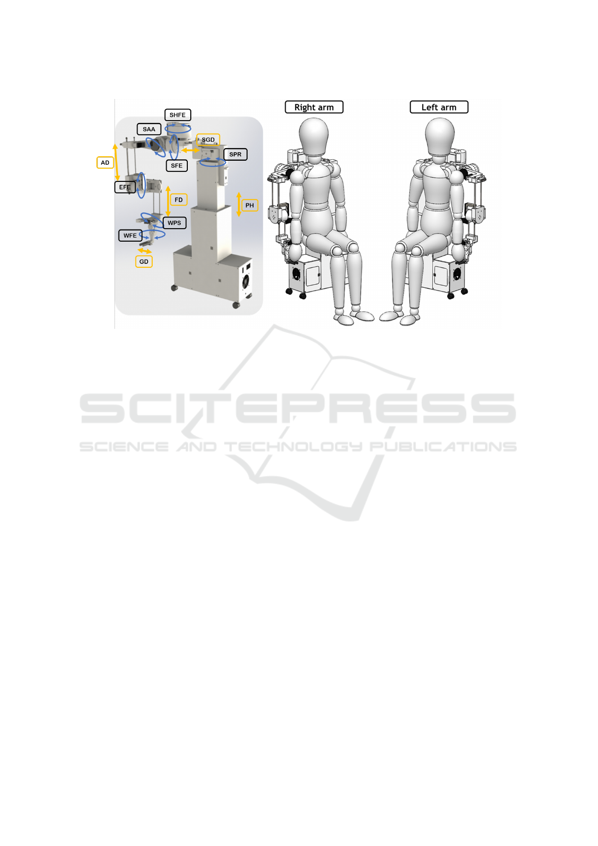
Figure 4: complete robotic assistive system design and arm switch configuration. SPR: shoulder protraction-retraction,
SHFE: shoulder flexion-extension, SFE: shoulder flexion-extension, SAA: shoulder adduction-abduction, EFE: elbow flexion-
extension, WPS: wrist pronation-supination, WFE: wrist flexion-extension, PH: patient height, SGD: scapulo-humeral to
gleno-humeral distance, AD: arm distance, FD: forearm distance and GD: grip distance
share the same frontal plane, and a locking mecha-
nism to execute the arm change configuration. This
mechanism allows to release the shoulder arm on an
axis to rotate it 180°. The actuators associated to
the flexion-extension and abduction-adduction move-
ments require planetary transmission. This is because
with this configuration a higher torque multiplica-
tion factor is obtained than with a belt transmission
(see the results in Figs. 3c and 3d). The planetary
transmission has a 1:8 ratio, which means a signif-
icant increase of the joints torque. As it is a rigid
transmission, helical gears are used to reduce noise
compared to spur gears. On the other hand, the ac-
tuator that performs the horizontal flexion-extension
movements does not require a substantial increase in
torque. Therefore, a belt drive is enough, since this
movement is performed in the horizontal plane, so
gravity does not affect.
Finally, the shoulder motion in the scapulo-
humeral part (pronation-supination) is an extension
of the horizontal flexion-extension movements of the
shoulder. So, in a similar way we have a belt transmis-
sion, which is enough because the movement is also
performed in the horizontal plane. This joint is impor-
tant as it supports the weight of the whole robotic arm
and the human arm. A reinforcement support is di-
rectly connected to the main base of the assistive sys-
tem. The base is composed of a structural system of
beams in the shape of an inverted T where the robotic
arm is housed in the upper part and this base functions
as a rail to correct the alignment height with respect
to the height of the patient. Rail guides are driven
by linear bearings and the movement is driven by lin-
ear actuators. The electronics, power supplies, control
systems and ventilation are located in the lower part,
to give more stability and robustness to the base of
the system. Finally, beaver-type wheels are included
to move the robotic system as needed. We present the
complete assistive robotic system in configuration for
left arm and right arm, and a render in Fig. 4.
5 CONCLUSIONS
This paper presents the procedure for the mechani-
cal design of a robotic assistive system for the reha-
bilitation of elbow tendinopathies. We present a se-
ries of guidelines for the design of this type of sys-
tems starting from an analysis of the physiological,
biomechanical and technological components associ-
ated with the pathology, supported also by motion
simulation studies where we consider joint mobility
ranges. Subsequently, we identified some qualitative
and quantitative design criteria that are of great im-
portance in the design of systems for physical rehabil-
itation, and we determined the complete workspace of
the upper limb, built the conceptual and mathematical
models of the system. We consider practical aspects
Mechanical Design of an Assistive Robotic System for Bilateral Elbow Tendinopathy Rehabilitation
327

of performance selection, and in addition, we propose
a never-before-seen arm switching configuration.
These criteria are a starting point in the systemati-
zation of the mechanical design processes of robotic
systems for physical assistance or rehabilitation. Fu-
ture work will be oriented to the construction of the
robotic assistive system, and the improvement of the
system as observed in practice.
FUNDING
This work is funded by Universidad Militar Nueva
Granada- Vicerrector
´
ıa de Investigaciones, under re-
search grant for project IMP-ING-3127, entitled
’Dise
˜
no e implementaci
´
on de un sistema rob
´
otico
asistencial para apoyo al diagn
´
ostico y rehabilitaci
´
on
de tendinopat
´
ıas del codo’.
REFERENCES
U.s. national library of medicine. el-
bow injuries and disorders.
https://medlineplus.gov/elbowinjuriesanddisorders.ht
ml. [Online; accessed March-2022].
ACP (1932). Physiotherapy: Its principles and practice. An-
nals of Internal Medicine, 6(2):298.
Avila-Chaurand, R., Prado-Le
´
on, L., and Gonz
´
alez-Mu
˜
noz,
E. (2007). Dimensiones antropom
´
etricas de la
poblaci
´
on latinoamericana : M
´
exico, Cuba, Colom-
bia, Chile / R. Avila Chaurand, L.R. Prado Le
´
on, E.L.
Gonz
´
alez Mu
˜
noz.
Ballantyne, R. and Rea, P. M. (2019). A game changer: ‘the
use of digital technologies in the management of up-
per limb rehabilitation’. In Advances in Experimental
Medicine and Biology, pages 117–147. Springer Inter-
national Publishing.
Bruder, A. M., Shields, N., Dodd, K. J., and Taylor, N. F.
(2017). Prescribed exercise programs may not be ef-
fective in reducing impairments and improving activ-
ity during upper limb fracture rehabilitation: a system-
atic review. Journal of Physiotherapy, 63(4):205–220.
Chaurand, R.
´
A., Le
´
on, L. R. P., and Mu
˜
noz, E.
L. G. (2007). Dimensiones antropom
´
etricas de
poblaci
´
on latinoamericana. Universidad de Guadala-
jara, CUAAD.
Contributors (2003). Rehabilitation of the hand & upper
limb. In Prosser, R. and Conolly, W. B., editors, Re-
habilitation of the Hand & Upper Limb, pages vii –
viii. Butterworth-Heinemann, Oxford.
Cort
´
es Rojas, M. F. and Ramos Moreno, I. R. (2017).
Revisi
´
on documental de los m
´
etodos diagn
´
osticos
y de tamizaje en des
´
ordenes m
´
usculo esquel
´
eticos
en miembros superiores de etiolog
´
ıa laboral.
http://hdl.handle.net/10554/39988.
Costa, J. T. D., Baptista, J. S., and Vaz, M. (2015). Inci-
dence and prevalence of upper-limb work related mus-
culoskeletal disorders: A systematic review. Work,
51(4):635–644.
Cruz Mart
´
ınez, G. M., Z-Avil
´
es, L., et al. (2020). Design
methodology for rehabilitation robots: Application in
an exoskeleton for upper limb rehabilitation. Applied
Sciences, 10(16):5459.
Dick, F. D., Graveling, R. A., Munro, W., and and, K. W.-B.
(2010). Workplace management of upper limb disor-
ders: a systematic review. Occupational Medicine,
61(1):19–25.
Fagher, K. and Lexell, J. (2014). Sports-related injuries
in athletes with disabilities. Scandinavian Journal of
Medicine & Science in Sports, 24(5):e320–e331.
Fierro, G. (2015). “anatom
´
ıa del hombro,” guido fierro
ortopedia y traumatolog
´
ıa - cirug
´
ıa de hombro y
codo. https://www.guidofierro.com/diagnostico-y-
tratamiento.
Gates, D. H., Walters, L. S., Cowley, J., Wilken, J. M., and
Resnik, L. (2015). Range of motion requirements for
upper-limb activities of daily living. American Jour-
nal of Occupational Therapy, 70(1):7001350010p1.
Gordon, C. C., Blackwell, C. L., Bradtmiller, B., Parham,
J. L., Barrientos, P., Paquette, S. P., Corner, B., Car-
son, J., Venezia, J. C., Rockwell, B. M., Mucher, M.,
and Kristensen, S. (1989). 2012 anthropometric sur-
vey of u.s. army personnel: Methods and summary
statistics.
Grupo, d. t. d. o. d. c. o. d. B. (2011). Epicondilitis y epitro-
cle
´
ıtis. revisi
´
on. Farmacia Profesional, 25(6):49–51.
Guatibonza, A. F., Solaque, L., and Velasco, A. (2018).
Kinematic and dynamic modeling of a 5-bar assistive
device for knee rehabilitation. In 2018 IEEE Third
Ecuador Technical Chapters Meeting (ETCM). IEEE.
Henning, T. (2010). Clinical tests for the musculoskele-
tal system: Examinations-signs-phenomena. JAMA,
303(15):1541.
Hillman, S. K. (2012). Core concepts in athletic training
and therapy with web resource. Annals of Internal
Medicine.
HOCOMA (-). Hocoma products overview. Online, ac-
cessed August-2020.
Islam, M. R., Brahmi, B., Ahmed, T., Assad-Uz-Zaman,
M., and Rahman, M. H. (2020). Exoskeletons in upper
limb rehabilitation: A review to find key challenges to
improve functionality. Control Theory in Biomedical
Engineering, pages 235–265.
Jabeen, T., Kazmi, S., Rehman, A., and Ahmed, S. (2016).
Upper and lower limbs disability and personality
traits. Journal of Ayub Medical College, Abbottabad:
JAMC, 28:348–52.
Keith L. Moore, A. F. D. and Agur, A. M. R. (2013). Moore,
anatom
´
ıa con orientaci
´
on cl
´
ınica. Wolters Kluwer
Health, S.A., Lippincott Williams & Wilkins.
Kessler, H. H. (1950). The principles and practices of reha-
bilitation. Physical Therapy, 30(3):126–127.
Knudson, D. (2007). Fundamentals of Biomechanics, Sec-
ond edition. Springer US.
ICINCO 2022 - 19th International Conference on Informatics in Control, Automation and Robotics
328

Kumar, S., W
¨
ohrle, H., Trampler, M., Simnofske, M., Pe-
ters, H., Mallwitz, M., Kirchner, E. A., and Kirchner,
F. (2019). Modular design and decentralized control
of the RECUPERA exoskeleton for stroke rehabilita-
tion. Applied Sciences (Switzerland), 9(4).
Lessard, S., Pansodtee, P., Robbins, A., Trombadore, J. M.,
Kurniawan, S., and Teodorescu, M. (2018). A Soft
Exosuit for Flexible Upper-Extremity Rehabilitation.
IEEE Transactions on Neural Systems and Rehabili-
tation Engineering, 26(8):1604–1617.
Linda, N., Maia, M., Hennen, L., Wolbring, G., Bratan, T.,
Kukk, P., Cas, J., Capari, L., Krieger-Lamina, J., and
Mordini, E. (2018). Assistive technologies for people
with disabilities - part ii: Current and emerging tech-
nologies.
Liu, K., Xiong, C. H., He, L., Chen, W. B., and Huang, X. L.
(2018). Postural synergy based design of exoskele-
ton robot replicating human arm reaching movements.
Robotics and Autonomous Systems, 99:84–96.
McHugh, G., Swain, I. D., and Jenkinson, D. (2013). Treat-
ment components for upper limb rehabilitation after
stroke: a survey of UK national practice. Disability
and Rehabilitation, 36(11):925–931.
Miao, Q., McDaid, A., Zhang, M., Kebria, P., and Li, H.
(2018). A three-stage trajectory generation method
for robot-assisted bilateral upper limb training with
subject-specific adaptation. Robotics and Autonomous
Systems, 105:38–46.
Miao, Q., Peng, Y., Liu, L., McDaid, A., and Zhang, M.
(2020a). Subject-specific compliance control of an
upper-limb bilateral robotic system. Robotics and Au-
tonomous Systems, 126:103478.
Miao, Q., Zhang, M., McDaid, A., Peng, Y., and Xie,
S. Q. (2020b). A robot-assisted bilateral upper limb
training strategy with subject-specific workspace: A
pilot study. Robotics and Autonomous Systems,
124:103334.
Milicin, C. and S
ˆ
ırbu, E. (2018). A comparative study of re-
habilitation therapy in traumatic upper limb peripheral
nerve injuries. NeuroRehabilitation, 42(1):113–119.
Occhionero, V., Korpinen, L., and Gobba, F. (2014). Upper
limb musculoskeletal disorders in healthcare person-
nel. Ergonomics, 57(8):1166–1191.
Olanrewaju, O. A., Faieza, A. A., and Syakirah, K. (2015).
Application of robotics in medical fields: Rehabili-
tation and surgery. Int. J. Comput. Appl. Technol.,
52(4):251–256.
Palacios, J. R. (2015). Sistema lo-
comotor extremidad superior.
https://www.infermeravirtual.com/esp/actividades de
la vida diaria/ficha/extremidad superior/sistema loc
omotor.
Ritchie, P. (2003). Sports injuries: Mechanisms, prevention,
treatment. second edition. Arthroscopy: The Journal
of Arthroscopic & Related Surgery, 19(4):448.
Romero-Acevedo, M., Guatibonza, A., and Velasco-Vivas,
A. (2018). Modular knee-rehabilitation device: Con-
figuration and workspace of assisted physical therapy
routines. In 2018 IEEE 2nd Colombian Conference
on Robotics and Automation (CCRA). IEEE.
Ruiz, D. M. C. (2011). Epicondilitis lateral: conceptos de
actualidad. revisi
´
on de tema. Revista Med de la Fac-
ultad de Medicina, 19(1):9.
Sanchez, D. M. Epicondylitis, arthroscopic surgery unit.
https://www.ucaorthopedics.com/patologias/codo/epi
condilitis/. [Online; accessed March-2022].
Sheng, B., Xie, S., Tang, L., Deng, C., and Zhang,
Y. (2019). An Industrial Robot-Based Rehabilita-
tion System for Bilateral Exercises. IEEE Access,
7:151282–151294.
SportMe. “las tendinitis del codo. epicondili-
tis y epitrocleitis” medical center sportme.
https://clinicabernaldez.com/tendinitis-del-codo-
dolor-de-codo-epicondilitis-epitrocleitis/. [Online;
accessed March-2020].
Sun, J., Shen, Y., and Rosen, J. (2021). Sensor reduction,
estimation, and control of an upper-limb exoskeleton.
IEEE Robotics and Automation Letters, 6(2):1012–
1019.
Taboadela, C. H. (2007). Goniometria una herramienta para
la evaluacion de las incapacidades. Medicine. ASO-
CIART SA ART, pages 1–130.
Ugurlu, B., Nishimura, M., Hyodo, K., Kawanishi, M., and
Narikiyo, T. (2015). Proof of Concept for Robot-
Aided Upper Limb Rehabilitation Using Disturbance
Observers. IEEE Transactions on Human-Machine
Systems, 45(1):110–118.
Vulliet, P., Chervin, J., Pierrart, J., Bourdillon, E., and
Masmejean, E. (2017). Patolog
´
ıas del codo y reha-
bilitaci
´
on. EMC - Kinesiterapia - Medicina F
´
ısica,
38(2):1 – 18.
Wattchow, K. A., McDonnell, M. N., and Hillier, S. L.
(2018). Rehabilitation interventions for upper limb
function in the first four weeks following stroke: A
systematic review and meta-analysis of the evidence.
Archives of Physical Medicine and Rehabilitation,
99(2):367–382.
WHO (2011). World report on disability. Technical report,
World Health Organization.
Wu, W., Fong, J., Crocher, V., Lee, P. V., Oetomo, D., Tan,
Y., and Ackland, D. C. (2018). Modulation of shoul-
der muscle and joint function using a powered upper-
limb exoskeleton. Journal of Biomechanics, 72:7–16.
Zhang, L., Guo, S., and Sun, Q. (2020). Development and
assist-as-needed control of an end-effector upper limb
rehabilitation robot. Applied Sciences, 10(19):6684.
Zimmermann, Y., Forino, A., Riener, R., and Hutter, M.
(2019). ANYexo: A Versatile and Dynamic Upper-
Limb Rehabilitation Robot. IEEE Robotics and Au-
tomation Letters, 4(4):3649–3656.
Mechanical Design of an Assistive Robotic System for Bilateral Elbow Tendinopathy Rehabilitation
329
