
Fixed-wing UAV Kinematics Model using Direction Restriction for
Formation Cooperative Flight
Yuxuan Fang, Yiping Yao, Feng Zhu* and Kai Chen
College of Systems Engineering, National University of Defense Technology, Changsha 410073, China
* Correspondence: zhufeng@nudt.edu.cn
Keywords: Trajectory Planning, Fixed-wing UAV, Kinematic Model, Formation Flight.
Abstract: Presently, existing fixed-wing UAV kinematics models typically require the planning algorithm to further
smooth the results to meet the trajectory requirements of the starting direction, while the commonly used
formation models often lead to track interference between formation members. In this paper, the formation
cooperative flight of fixed-wing UAVs was modeled. First, the linear velocities in the three-dimensional
direction of the traditional UAV model were changed to a linear velocity along the flight direction of the UAV,
and the turning angular velocities and linear acceleration were set to establish the kinematics model. Then,
based on the "Lead plane-Wingman" formation control structure, the order of friendly aircraft avoidance was
defined by setting the priority of the formation members, and the target point of the wingman was dynamically
calculated according to the target formation and real-time position of the leader plane. Finally, a UAV
formation cooperative flight model was obtained. Considering the formation of five UAVs as an example, a
simulation experiment was carried out, the results of which showed that the trajectory obtained based on the
above model could meet the kinematics and collision avoidance requirements in formation flight of the fixed-
wing UAVs.
1 INTRODUCTION
Presently, unmanned aerial vehicles (UAV) are widely
used in many fields, such as disaster detection, low-
altitude reconnaissance, atmospheric research,
communication relay, disaster area search, and rescue
missions (Qadir et al., 2021; Qu et al., 2014;
Sivakumar & TYJ, 2021). Some of the tasks involved
in these areas have security risks or require long
periods of continuous operation, making them
unsuitable for manned aircraft, contrast to UAVs
(Rajasree & Jisha, 2015). Compared with the rotor
UAV, the fixed-wing UAV has advantages of long
flight distance, long flight time, high speed, and higher
load capacity. It is suitable for missions with long
continuous working hours and high requirements for
airborne equipment (Y. et al., 2021). Currently, the
mission execution capability of a single UAV is
limited, and a UAV formation can improve the
efficiency at which missions are executed. A
reasonable formation can reduce task costs (i.e., by
saving fuel) (Qiannan et al., 2014) and improve
mission execution effectiveness (i.e., by increasing the
search scope) (Seiler et al., 2002). The planning of a
safe and feasible trajectory for each UAV according to
preset formation requirements is an important task in
the current fixed-wing UAV formation research (Gul
et al., 2021; Sharma et al., 2021). Reasonable UAV
kinematics and formation cooperative flight models
can provide appropriate constraints and planning
objectives for the trajectory planning of a UAV
formation (Aggarwal & Kumar, 2020), which makes
the planning results more feasible.
In the trajectory planning of UAVs, owing to
certain limitations of fixed-wing aircraft, including
flight direction and speed, there is a high demand for
flight-path feasibility. The common method is to
consider the UAV as a particle for trajectory planning
purposes and then smooth the results to get a
trajectory that meets the requirements (Huang et al.,
2016; Maini & Sujit, 2016; Sahingoz, 2014). By using
appropriate kinematic models to provide constraints,
the algorithm can consider the requirements of the
UAV in the track starting direction of the planning
process. However, in the scenario of multiple UAVs
flying together, coordination among the UAVs is the
main problem. Changing the UAV formation requires
changing the flight state of each UAV according to the
92
Fang, Y., Yao, Y., Zhu, F. and Chen, K.
Fixed-wing UAV Kinematics Model using Direction Restriction for Formation Cooperative Flight.
DOI: 10.5220/0011299200003274
In Proceedings of the 12th International Conference on Simulation and Modeling Methodologies, Technologies and Applications (SIMULTECH 2022), pages 92-101
ISBN: 978-989-758-578-4; ISSN: 2184-2841
Copyright
c
2022 by SCITEPRESS – Science and Technology Publications, Lda. All rights reserved

mission requirements and environmental restrictions.
In this regard, the cooperation of all UAVs required.
That is, the flight trajectory of each UAV cannot be
planned independently. If the planning is based on a
simple formation model, interference of trajectories
can easily occur, which may make members of the
formation collide or result in difficulties maintaining
the target formation. Therefore, the path planning
algorithm must be based on reasonable UAV
kinematics and formation models to ensure feasibility
of the results (Tsourdos et al., 2011).
Based on the flight characteristics of fixed-wing
aircraft, a kinematics model for the fixed-wing UAV
can be established. According to the formation
structure of "Lead plane-Wingman" (Zhu et al., 2017),
the formation cooperation model of the UAV can be
established by designing formation flight rules for
both the lead plane and wingmen. Therefore, a fixed-
wing UAV kinematics model and a UAV formation
cooperative flight model are proposed in this paper.
The main contributions of this study are as follows:
1. A kinematics model for the fixed-wing UAV is
proposed. The linear and turning angular velocities
along the flight direction of the UAV are used to
replace the linear velocity in the three-dimensional
direction of the traditional UAV model, and the linear
acceleration is set, which meet the requirements of the
starting direction of the UAV in the planning results.
2. A UAV formation cooperative flight model is
proposed. Based on the formation structure of "Lead
plane-Wingman", the target points of the wingmen
are updated in real time according to the requirements
of the formation and position of the lead plane in the
process of formation flight. Priority is set for the
members of the formation to specify the order in
which UAVs avoid their teammates.
It should be noted that the situation addressed in
this study is the path planning level of the UAV, which
does not involve the design of the flight control
system at the bottom of the UAV (Y. et al., 2021).
This paper is organized as follows: Section 2
introduces current related research. Sections 3 and 4
introduce the models proposed in this paper. Section
5 presents the verification and experimental analyses.
Section 6 presents the conclusions and future work.
2 RELATED WORK
2.1 Kinematic Modeling of Fixed-wing
UAV
Establishing a kinematics model for the UAV is the
basis for trajectory planning. Feng et al. proposed a
hybrid algorithm that can effectively deal with the
influence of dynamic obstacles. However, due to the
lack of kinematic models for fixed-wing UAVs, its
planning result requires the UAV to avoid obstacles
by hovering first and then making a detour, which is
not a feasible flight trajectory (Feng et al., 2021).
Chen et al. modelled a UAV and used the artificial
potential field method to realize formation flight of
multiple UAVs, but the model does not consider the
flight characteristics of the fixed-wing UAV, which
leads to a large oscillation in the flight path; therefore,
this method is not ideal for the flight trajectory
planning of the fixed-wing UAV (Chen et al., 2015).
Phung and Ha combined many motion parameters of
the UAV as constraints and used a planning algorithm
to obtain the spherical vector-based particle swarm
optimization algorithm, thereby optimizing the track
point; however, this method does not consider the
starting flight direction of the UAV (Phung & Ha,
2021). Manathara and Ghose established a fixed-wing
UAV model to study the problem of multiple aircraft
reaching a destination simultaneously and solved the
constraint condition of the starting direction of the
UAV using Dubins curve (Manathara & Ghose, 2012).
However, the model only considers the direction
constraint of two-dimensional space and requires
UAVs to fly at a fixed speed; therefore, the planning
result based on this model has difficulties meeting the
requirements of UAVs in real scenarios.
2.2 Design of UAV Formation
Cooperative Flight Model
Establishing a UAV formation cooperation model is
important for UAV formation flight safety and
formation adjustment flexibility. Zhang et al.
modelled the formation of fixed-wing UAVs, but the
proposed planning method had few constraints on the
formation control model, resulting in poor
coordination among teammates and lack of flexibility
in formation adjustments (Zhang et al., 2018). Wei et
al. proposed a path planning model for multiple UAVs
based on the ant colony algorithm, but the model does
not study the formation coordination strategy;
therefore, the calculation results based on this model
show that the trajectories among UAVs are
independent and do not have the characteristics of
formation flight (Bai et al., 2021). Zhu et al.
established a multi-aircraft model for the formation
maintenance of multiple UAVs, but the model only
regulates the formation members in the formation
maintenance stage and cannot provide constraints and
planning objectives for the planning algorithm in the
formation assembly stage (Zhu et al., 2017).
Fixed-wing UAV Kinematics Model using Direction Restriction for Formation Cooperative Flight
93
In summary, regarding meeting the motion
performance constraints of the fixed-wing UAV, the
existing research models have some problems, that is,
the track is not smooth, the initial direction is not
considered, and the speed of the UAV is strictly
limited. In the research of formation flight, some of
the formation models focus on maintaining the
formation, while some prevent multi-aircraft
trajectory conflict by avoiding path crossover.
Therefore, these models have difficulties meeting the
coordination and cooperation requirements of UAVs
in formation flight.
3 KINEMATICS MODELING OF
FIXED-WING UAV USING
DIRECTION RESTRICTION
3.1 Position and Attitude Description of
UAV
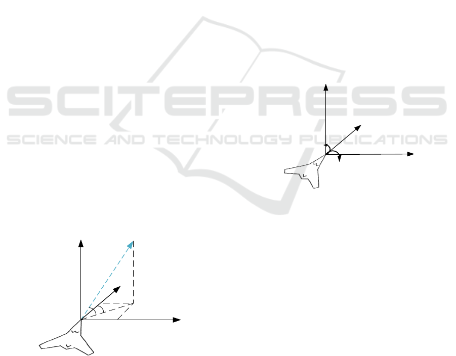
First, it is necessary to describe the position and
attitude of the UAV. A coordinate system that is
relatively stationary to the ground is defined, which is
called an inertial coordinate system (ICS) in this study,
and is marked as 𝑆
𝑜
𝑥
𝑦
𝑧
. As shown in Figure
1, where 𝑜
is a certain point on the ground, 𝑜
𝑥
points in a certain direction of the horizontal plane,
𝑜
𝑥
𝑦
is the horizontal plane, and 𝑜
𝑧
is
perpendicular to the ground and points to the sky. This
coordinate system conforms to the right-hand rule and
is used to represent the position and attitude of the
UAV in this study. This study focuses on the level of
route planning; therefore, the state matrix, P, of the
UAV in the inertial system is defined as follows:
𝑷=
𝑥𝑦𝑧𝜃𝜓
(1)
o
f
v
θ
ψ
z
f
x
f
y
f
Figure 1: Inertial Coordinate System.
where x, y, and z are the coordinate positions of the
UAV in the ICS and 𝜃 and 𝜓 represent the attitude
information of the UAV. 𝜃 is the pitch angle (−𝜋/2≤
𝜃≤𝜋/2), and 𝜓 is the yaw angle (azimuth) (−𝜋≤
𝜓≤𝜋). This study runs at the planning level and does
not consider specific details of the UAV movement
process; therefore, it is not necessary to define the roll
angles of the UAV.
3.2 Motion State Modeling of UAV
based on Direction Restriction
A coordinate system that is relatively stationary to the
UAV is defined, which is called the vehicle coordinate
system (VCS) in this study, and is denoted by
𝑆
(
𝑜
𝑥
𝑦
𝑧
)
, w h e r e 𝑜
is a fixed position on the
UAV at some point in time, 𝑜
𝑥
points in the
direction of the head of the UAV and is in the same
direction during flight, 𝑜
𝑦
is parallel to the
horizontal plane and points to the right side of the
U AV, a n d 𝑜
𝑧
is vertically horizontal and points to
the top of the UAV. This coordinate system conforms
to the right-hand rule and is used to describe the
motion state of the UAV. The motion state matrix of
the UAV in the VCS is expressed as follows:
𝑣
𝑣
𝑣
𝑎
𝑎
𝑎
(2)
𝑣
𝜓
𝑣
l
𝑣
θ
o
v
z
v
x
v
y
v
Figure 2: Vehicle Coordinate System.
As shown in Figure 2, the linear, pitching angular
and yaw angular velocities of the UAV are denoted by
𝑣
, 𝑣
and 𝑣
, respectively. The linear, pitch angular
and yaw angular accelerations of the UAV are
denoted by 𝑎
, 𝑎
and 𝑎
, respectively.
The following assumptions are made about the
kinematic characteristics of the fixed-wing UAV:
1.The linear acceleration of the UAV is constant,
that is, 𝑎
is constant.
2.The UAV turns at a constant angular velocity.
3.The velocities of the UAV have an upper limit,
and the linear velocity has a lower limit, 𝑣
, which
is greater than 0.
The velocity matrix, 𝑽 , and the acceleration
matrix, 𝒂, are obtained as follows:
SIMULTECH 2022 - 12th International Conference on Simulation and Modeling Methodologies, Technologies and Applications
94
𝑽=
𝑣
𝑣
𝑣
𝒂=
𝑎
𝑎
𝑎
(3)
According to the previous hypothesis, the
relationship between the velocity and acceleration is
as follows:
𝑽
(
𝑡
+∆𝑡
)
=
100
000
000
∙𝑽
(
𝑡
)
+
𝒇
(𝑡
)∙
∆𝑡00
010
001
∙𝒂
(4)
𝒇
=
𝑓
00
0
𝑓
0
00
𝑓
(5)
where 𝑽
(
𝑡
)
is the velocity matrix of the UAV at time
𝑡
, ∆𝑡(s) is the step size of the time advance, and 𝒇 is
the velocity change trend matrix of the UAV. The
values of 𝑓
, 𝑓
,and 𝑓
are selected from 1, 0, and -1,
respectively, according to the requirements of the
planning algorithm at time 𝑡
. Consequently, the
relationship between the position and attitude of the
UAV as well as its velocity are obtained as follows:
⎩
⎪
⎨
⎪
⎧
𝑥=𝑣
cos𝜃 cos𝜓
𝑦=𝑣
cos𝜃 sin𝜓
𝑧=𝑣
sin𝜃
𝜃
=𝑣
𝜓
= 𝑣
(6)
4 PRIORITY AVOIDACE BASED
UAV FORMATION
COOPERATIVE FLIGHT
MODEL
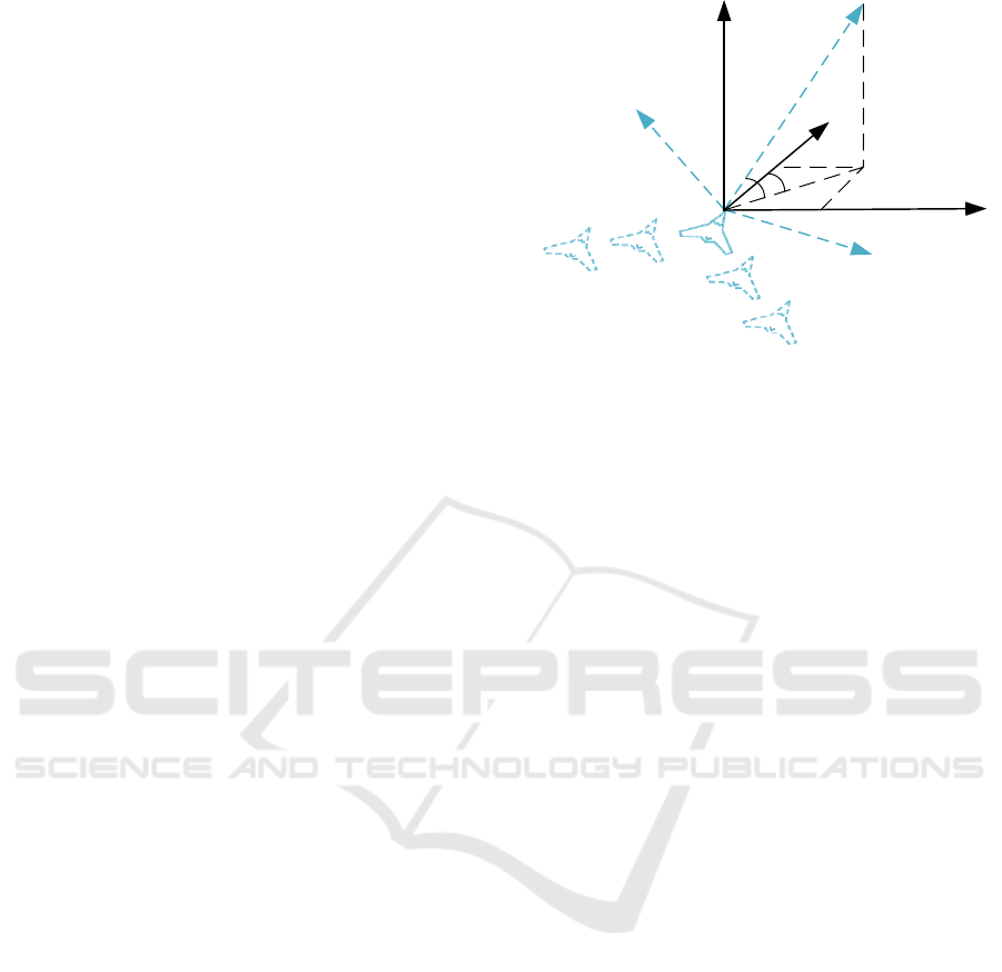
4.1 Description of Formation Location
The formation in this study consists of a lead plane
and several wingmen. The role of the lead plane in the
formation is to lead the formation to fly to the target
area; therefore, the target point of the lead plane is set
in advance. The positions of the wingmen in the target
formation become their local target point, which
changes with the state of the lead aircraft. Therefore,
the target point of a wingman at a certain time must
be determined by the preset formation parameters and
current position and posture of the lead plane.
As shown in Figure 3, considering the V-shaped
formation as an example, the coordinate system
represented by the black solid line is the ICS. The
blue solid line represents a UAV as the lead plane, and
the blue dotted lines represents the local target points
of the wingmen. At this time, the lead plane is located
xv
zv
yv
o
z
f
xf
yf
θ
ψ
Wingmen
Lead plane
Figure 3: Method for Determining Wingmen Target Point.
at a certain point in the ICS. The coordinate system,
represented by the blue dotted line, represents the
VCS of the lead plane. If the lead plane is UAV 0, then
the equation for calculating the local target points of
the wingmen at a certain time is as follows:
𝑮
=
𝑨
𝒗𝒇
∙𝑩
𝒗𝒇
∙
𝑥
𝑦
𝑧
+
𝑥
𝑦
𝑧
(7)
𝑨
𝒗𝒇
=
cos𝜓
−sin𝜓
0
sin𝜓
cos𝜓
0
001
(8)
𝑩
𝒗𝒇
=
cos𝜃
0sin𝜃
010
sin𝜃
0 cos𝜃
(9)
where matrix 𝑮
=
𝑥
𝑦
𝑧
is the local target
point of jth wingman (j = 1, 2,…, n) in the ICS, 𝑨
𝒗𝒇
and 𝑩
𝒗𝒇
are matrices that transform coordinates from
the VCS to the ICS, 𝜓
and 𝜃
are the yaw and pitch
angles of the lead plane in the ICS, respectively,
𝑥
𝑦
𝑧
is the target point of a wingman
under the VCS of the lead plane,
𝑥
𝑦
𝑧
i s t h e
position of the lead plane under the ICS.
4.2 Coordination Rules for Formation
Members based on Avoidance
Priority
There may be a risk of collision between UAVs
during flight; therefore, it is necessary to formulate
obstacle avoidance rules for each UAV. The strategy
adopted in this study is to endow each UAV with the
characteristics of the obstacles, including their
position and size. When each UAV is flying towards
its target, the other UAVs are regarded as moving
obstacles.
Fixed-wing UAV Kinematics Model using Direction Restriction for Formation Cooperative Flight
95
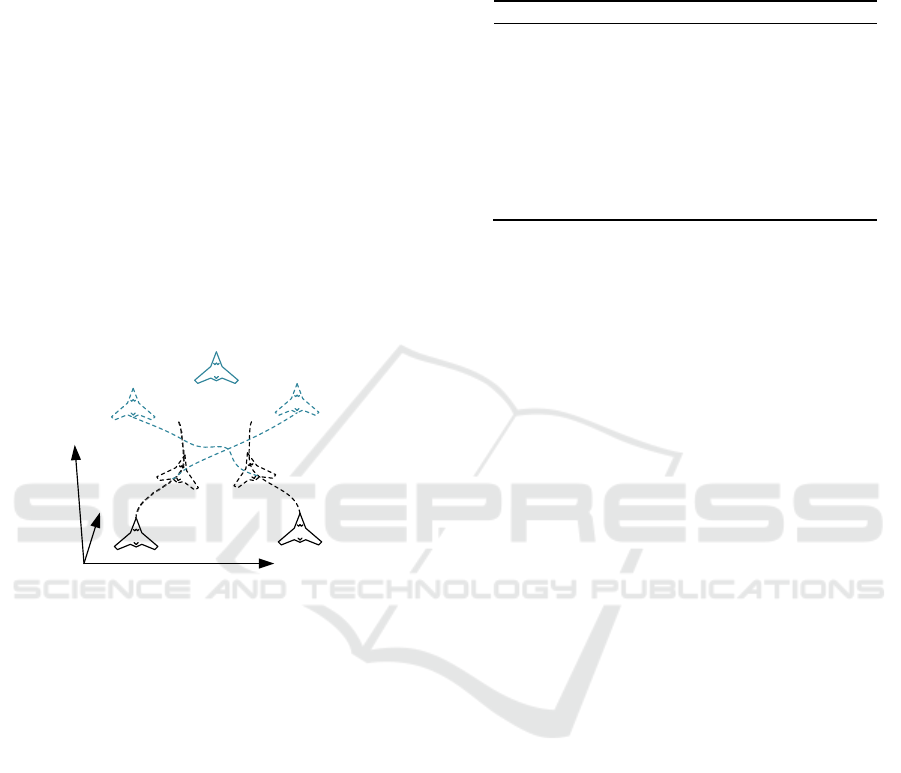
In the UAV flight process, UAVs may avoid each
other in certain cases. Considering the case shown in
Figure 4 as an example, in a certain state, the target
point of Wingman 1, which is on the left, is on the
right, whereas the target point of Wingman 2, which
is on the right, is the opposite, and both wingmen fly
on the same horizontal plane. In this case, Wingman
1 must move in the positive direction of the 𝑜
𝑦
axis
to get close to the target point, whereas Wingman 2
must move in the opposite direction. During flight,
the distance between the two wingmen continuously
decreases. When the distance is sufficiently small, the
two wingmen perform an obstacle avoidance
operation. Because of the particularity of this scene,
the motion characteristics of the two wingmen are
geometrically symmetrical, so they repeatedly avoid
each other. As shown by the black dotted line track in
Figure 4, the wingmen eventually have difficulties
reaching the target points.
Wingman 1
Wingman 2
Target point
of Wingman 1
Target point
of Wingman 2
Lead plane
O
f
x
f
y
f
z
f
Figure 4: Mutual avoidance between wingmen.
To solve this problem, in this study, the avoidance
strategy of formation members is designed by setting
priority. In the initial setup, before the beginning of
the planning, the members of the formation are
numbered, and the order in which each UAV avoids
the others is defined according to the principle that
the priority decreases as the number increases.
According to this rule, in the case shown in Figure 4,
Wingman 1 only has to avoid the lead plane, whereas
Wingman 2 has to avoid the captain and Wingman 1.
Using this rule, the trajectories of the two wingmen
entering the avoidance phase can be obtained, as
shown by the blue dotted line in Figure 4.
5 SIMULATION RESULTS AND
ANALYSIS
The formation designed in this study consisted of five
fixed-wing UAVs, comprised of one lead plane and
four wingmen. This stipulates that all UAVs are
isomorphic (i.e., the performance is the same). The
performance parameters are listed in Table 1.
Table 1: Performance Parameter.
Parameter Type Value
UAVs'𝑅
(
𝑚
)
50
Initial 𝑣
(
𝑚𝑠
⁄)
100
𝑎
(𝑚/𝑠
)
10 (
𝑓
>0)
40 (
𝑓
<0)
𝑎
(
𝑟𝑎𝑑 𝑠
⁄)
𝜋/6
𝑎
(
𝑟𝑎𝑑 𝑠
⁄)
𝜋/6
Speed range
300≥𝑣
≥100
(
𝑚𝑠
⁄)
𝜋/6 ≥ 𝑣
≥−𝜋/6
(
𝑟𝑎𝑑 𝑠
⁄)
𝜋/6 ≥ 𝑣
≥−𝜋/6
(
𝑟𝑎𝑑 𝑠
⁄)
where 𝑅
is the collision radius of the UAV, that is,
the distance between the UAV and other obstacles
must not be less than 𝑅
; otherwise, it is considered
that the UAVs have collided.
5.1 Simulation Experiment of the
Kinematic Model of Fixed-wing
UAV
In this section, the simulation experiments based on
the fixed-wing UAV kinematics model proposed in
this paper, carried out to verify the rationality of the
trajectory planning results, are presented. In the
mission scene of the experiment, after dynamic
adjustment in the process of flying in the
predetermined direction, the five fixed-wing UAVs
fly to the new target area according to the newly
specified formation.
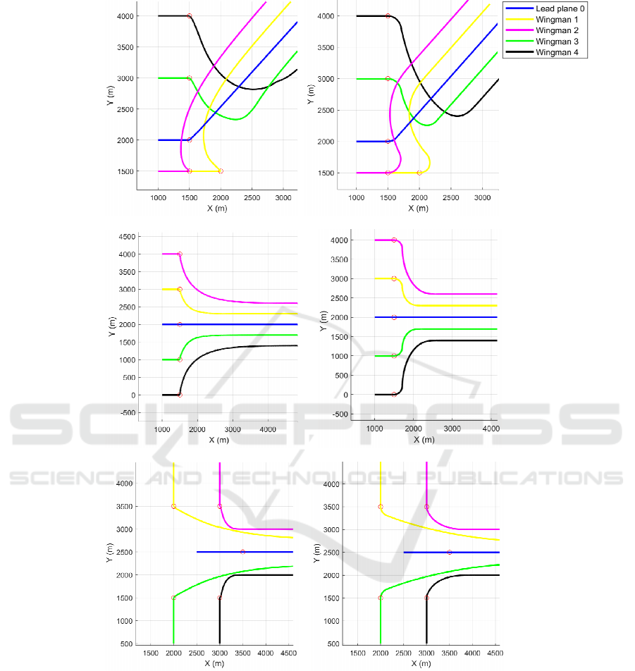
Based on the traditional UAV kinematics model
(Feng et al., 2021; Goerzen et al., 2010) and fixed-
wing UAV kinematics model proposed in this paper,
trajectory planning was carried out from the preset
starting point, and the trajectories near the starting
point of the UAV formation in three different initial
scenes were obtained, as shown in Figure 5. The red
circle in the picture is the starting point for the
formation of the UAVs. It can be deduced from the
figure that because the traditional UAV kinematics
model only considers the position of the UAV in the
constraints of the trajectory planning algorithm, the
resulting track requires the UAV to turn from a large
angle at the starting point of the planning.
Considering the pink and yellow tracks in Figure 5(a)
as an example, the initial direction of the planned
flight trajectory deviates greatly from the original
flight direction of the UAV, which is not in line with
the actual flight situation of the fixed-wing UAV.
However, the kinematics model proposed in this
paper considers not only the position constraints of
SIMULTECH 2022 - 12th International Conference on Simulation and Modeling Methodologies, Technologies and Applications
96
(a) (b)
(c) (d)
(e) (f)
Figure 5: Trajectories generated based on the traditional model and the model proposed in this paper. (a, c, and e): traditional
model; (b, d, and f): model proposed in this paper).
the UAV, but also the direction adjustment restrictions
of the UAV; therefore, the resulting track is more
continuous and more in line with the actual flight
situation of the UAV
5.2 Simulation Experiment of the UAV
Formation Cooperative Flight
Model
This section presents the simulation experiments
carried out in several scenes to verify the feasibility
of the UAV formation cooperative flight model
Fixed-wing UAV Kinematics Model using Direction Restriction for Formation Cooperative Flight
97

(a)
(b)
(c)
(d)
Figure 6: Trajectory planning based on the UAV formation cooperative flight model.
proposed in this paper, including teammates collision
avoidance rules and formation flight ability.
Figure 6 shows the trajectory planning results of
each fixed-wing UAV, from the specified starting
point to the target point in four scenarios. Figures
6(a)–(c) show the trajectory planning results of the
formation members from different starting points and
directions. Figure 6(d) shows the flight trajectory
planning results of the UAV formation flight from the
original formation to their respective target points.
From the figure, we can observe that the tracks of
some formation members have crossed, which is a
relatively common situation in the actual environment
and requires the coordination of various UAVs to
prevent interference or conflict in trajectory planning.
The UAV formation cooperative flight model
proposed in this paper sets priority rules for formation
members to avoid conflict among them. Therefore,
when planning based on the model, if there is a
trajectory conflict, a flight path for avoiding the
teammate is planned according to the priority order.
As shown in Figure 6, the UAVs represented by
different color tracks have different priorities;
therefore, they avoid teammates that have proprieties
higher than their own and form a specified formation
or fly to their designated target area through a safe
flight trajectory. This verifies the feasibility of the
model proposed in this paper.
5.3 Comprehensive Simulation
Experiment
In this section, the artificial potential field method is
used to test the fixed-wing UAV kinematics model
and UAV formation cooperative flight model
proposed in this paper, thereby verifying that the
planning results based on these models are feasible
and can meet the collision avoidance requirements
among teammates.
According to the performance parameters
specified in Table 1, the flight trajectory planning
results of the formation flight and decentralization
process of five fixed-wing UAVs are shown in figure
7. Each UAV forms a target formation from the circle
in the figure and then flies in formation for a period
of time.
Figure 7: Formation flying and decentralization trajectory
planning of UAVs.
SIMULTECH 2022 - 12th International Conference on Simulation and Modeling Methodologies, Technologies and Applications
98

Finally, the UAVs decentralize at the square box
in the figure and fly to their respective target areas
(triangle in the figure). As can be seen from the figure,
the algorithm is solved based on the kinematics model
for fixed-wing UAVs. Therefore, the generated
trajectory considers the initial flight direction of each
UAV, and the trajectory curve can better meet the
constraints of the trajectory tracking for fixed-wing
UAVs under actual conditions.
Figure 8 shows the distance between the wingmen
and the target points during the formation flight stage.
In this stage, the target point of each wingman is set
by the multi-UAV formation cooperative model
according to the position of the lead plane. As can be
seen from the figure, the wingmen fly from their
starting points to their respective target points.
Eventually, all the wingmen form a target formation
and continue to fly in formation with the lead plane.
Figure 9 shows the minimum distance among the
members of the formation and other UAVs during the
flight process. In the initial stage, the wingmen must
adjust their flight direction at a large angle to
assemble to the lead plane, so the distances among the
members of the formation changes abruptly.
Subsequently, the UAVs formed the designated
formation, and the distances among the members of
the formation remained stable. For approximately 25
s, as can be observed in the figure, the UAVs spread
out and flew to their respective target areas.
Figure 8: The situation of wingmen following the target points during the formation flight stage.
Figure 9: Minimum distance among formation members and teammates.
Fixed-wing UAV Kinematics Model using Direction Restriction for Formation Cooperative Flight
99

According to the setting in Table 1, the distances
among the UAVs should not less than 100 m. The
planning results show that the minimum distance
between each UAV and teammates is more than 100
m (red dotted line in the figure) during the entire flight,
and the UAVs can maintain a stable distance until the
formation is broken.
Thus, it can be observed that the fixed-wing UAV
kinematics model proposed in this paper can provide
constraints for the trajectory planning algorithm and
can meet the requirements of fixed-wing UAVs in a
real environment. Furthermore, it can effectively
provide the planning objectives and coordination
strategies of each UAV for the trajectory planning
algorithm, thereby improving formation flight and
meeting the requirements for collision avoidance
among teammates.
6 CONCLUSIONS
In this paper, considering the motion characteristics
of fixed-wing aircraft, a kinematic model suitable for
fixed-wing UAV was established. Subsequently,
based on the formation structure of "Lead plane-
Wingman", a UAV formation cooperative flight
model was established. Through a comparative
experiment with the traditional model, it was verified
that the fixed-wing UAV kinematics model can better
meet the motion constraints of the fixed-wing UAV.
Through simulation experiments using multiple
scenes, it was verified that the UAV formation
cooperative flight model can provide a processing
strategy for the cooperation and collision avoidance
among UAVs. Finally, through a complex mission
scene, it was verified that the planning results of a
multi-UAV flight based on the model proposed in this
paper can meet the flight trajectory feasibility and
collision avoidance requirements among teammates
during formation flight. The above experiments
showed that the model proposed in this paper can
provide the basis for the research on the formation
flight trajectory planning of the fixed-wing UAV.
However, the influences of the complexity of the
kinematics model and different collision avoidance
priority combinations on the planning algorithm and
planning results, respectively, were not investigated
in this study. In the future work, optimization of the
fixed-wing UAV formation model and a formation
emergency handling strategy will be investigated.
ACKNOWLEDGEMENTS
This research was funded by the National Natural
Science Foundation of China (no. 61903368).
REFERENCES
Aggarwal, S., Kumar, N. (2020). Path planning techniques
for unmanned aerial vehicles: A review, solutions, and
challenges. Computer communications, 149, 270–299.
Bai, X., Jiang, H., Cui, J., Lu, K., Chen, P., Zhang, M.
(2021). UAV path planning based on improved A∗ and
DWA algorithms. International journal of aerospace
engineering, 2021, 1–12. http://doi.org/10.1155/
2021/4511252
Chen, Y., Yu, J., Su, X., Luo, G. (2015). Path planning for
multi-UAV formation. Journal of intelligent & robotic
systems, 77(1), 229–246. http://doi.org/10.1007/
s10846-014-0077-y
Feng, J., Zhang, J., Zhang, G., Xie, S., Ding, Y., Liu, Z.
(2021). UAV dynamic path planning based on obstacle
position prediction in an unknown environment. IEEE
Access, 9, 154679–154691. http://doi.org/10.1109/
ACCESS.2021.3128295
Goerzen, C., Kong, Z., Mettler, B. (2010). A survey of
motion planning algorithms from the perspective of
autonomous UAV guidance. Journal of intelligent and
robotic systems, 57(1–4), 65–100. http://doi.org/
10.1007/s10846-009-9383-1
Gul, F., Mir, I., Abualigah, L., Sumari, P., Forestiero, A.
(2021). A consolidated review of path planning and
optimization techniques: Technical perspectives and
future directions. Electronics, 10(18), 2250.
http://doi.org/10.3390/electronics10182250
Huang, L., Qu, H., Ji, P., Liu, X., Fan, Z. (2016). A novel
coordinated path planning method using k-degree
smoothing for multi-UAVs. Applied soft computing, 48,
182–192. http://doi.org/10.1016/j.asoc.2016.06.046
Maini, P., Sujit, P. B. (2016). Path planning for a UAV with
kinematic constraints in the presence of polygonal
obstacles. 2016 International Conference on Unmanned
Aircraft Systems (ICUAS).
Manathara, J. G., Ghose, D. (2012). Rendezvous of multiple
UAVs with collision avoidance using consensus.
International journal of aerospace engineering
http://doi.org/10.1061/(ASCE)AS.1943
Phung, M. D., Ha, Q. P. (2021). Safety-enhanced UAV path
planning with spherical vector-based particle swarm
optimization. Applied soft computing, 107, 107376.
http://doi.org/10.1016/j.asoc.2021.107376
Qadir, Z., Ullah, F., Munawar, H. S., Al-Turjman, F. (2021).
Addressing disasters in smart cities through UAVs path
planning and 5G communications: A systematic review.
Computer communications, 168, 114–135.
http://doi.org/10.1016/j.comcom.2021.01.003
Qiannan, Z., Ziyang, Z., Chen, G., Ruyi, D. (2014). Path
planning of UAVs formation based on improved ant
SIMULTECH 2022 - 12th International Conference on Simulation and Modeling Methodologies, Technologies and Applications
100

colony optimization algorithm. Paper presented at the,
Yantai.
Qu, Y., Zhang, Y., Zhang, Y. (2014). Optimal flight path
planning for UAVs in 3-D threat environment. Paper
presented at the.
Rajasree, R., Jisha, V. R. (2015). Optimal formation control
of unmanned aerial vehicles with reconfiguration.
Paper presented at the 2015 International Conference
on Control, Communication & Computing, Trivandrum
India.
Sahingoz, O. K. (2014). Generation of bezier curve-based
flyable trajectories for multi-UAV systems with parallel
genetic algorithm. Journal of intelligent & robotic
systems, 74(1–2), 499–511. http://doi.org/10.1007/
s10846-013-9968-6
Seiler, P., Pant, A., Hedrick, K. (2002). Analysis of bird
formations. Paper presented at the.
Sharma, A., Shoval, S., Sharma, A., Pandey, J. K. (2021).
Path planning for multiple targets interception by the
swarm of UAVs based on swarm intelligence algorithms:
A review. Technical review - IETE, 1–23.
http://doi.org/10.1080/02564602.2021.1894250
Sivakumar, M., TYJ, N. M. (2021). A literature survey of
unmanned aerial vehicle usage for civil applications.
Journal of aerospace technology and management, 13
http://doi.org/10.1590/jatm.v13.1233
Tsourdos, A., White, B., Shanmugavel, M. (2011).
Cooperative Path Planning of Unmanned Aerial
Ve hi cl es . A John Wiley and Sons, Ltd., Publication.
Wang, Y., Yue, Y., Shan, M., He, L., Wang, D. (2021).
Formation reconstruction and trajectory replanning for
multi-UAV patrol. IEEE/ASME Transactions on
Mechatronics, 26(2), 719–729. http://doi.org/
10.1109/TMECH.2021.3056099
Zhang, J., Yan, J., Zhang, P. (2018). Fixed-wing UAV
formation control design with collision avoidance based
on an improved artificial potential field. IEEE Access,
6, 78342–78351. http://doi.org/10.1109/
ACCESS.2018.2885003
Zhu, X., Zhang, X., Yan, M., Qu, Y. (2017). Three-
dimensional formation keeping of multi-UAV based on
consensus. Journal of central south university, 24(6),
1387–1395. http://doi.org/10.1007/s11771-017-3543-4
Fixed-wing UAV Kinematics Model using Direction Restriction for Formation Cooperative Flight
101
