
Dynamic Slotted Network Coding Protocol
Mohammed Aissaoui
1,2 a
, Chiraz Houaidia
1 b
, Adrien van Den Bossche
2 c
, Thierry Val
2 d
and Le
¨
ıla Azouz Saidane
1 e
1
ENSI-University of Manouba, ENSI, Tunisia
2
IRIT-University of Toulouse - Jean Jaur
`
es, France
Keywords:
Wireless Networks, Network Coding, Physical-layer Network Coding, Two-way Relay Channel, Scheduling.
Abstract:
Network Coding (NC) is a technique that enhances the performance of wireless networks by increasing the
throughput and decreasing the delay. The basic idea is to exploit the mixing of signals that occurs naturally
when end nodes transmit at the same time. The main challenge stands for a medium access scheduling allowing
synchronized coordination between the nodes involved in that coded transmission. Most of the proposed
Medium Access Control (MAC) protocols are based either on the CSMA/CA or the TDMA scheduling. The
CSMA/CA based protocols suffer from synchronization issues, while the TDMA based protocols suffer from
the delay due to their static design. This paper introduces a new NC MAC protocol called Dynamic Slotted
Network Coding Protocol (DSNCP) based on a time scheduling to avoid the synchronization issue and uses a
new design that makes the data slot assignments dynamic in order to reduce the delay.
Simulation results show a significant performance gain of the proposed DSNCP compared to CSMA/CA
and static TDMA protocols in terms of throughput and delay. In some scenarios, the throughput gain of the
DSNCP could reach 130 % and 100 % compared to TDMA and CSMA/CA, respectively, and the delay gain
could reach 80 % and 40 % compared to TDMA and CSMA/CA, respectively.
1 INTRODUCTION
Network Coding (NC) is relatively a recent field of
interest which appears for the first time in (Ahlswede
et al., 2000). NC is an alternative to the traditional
store and forward relaying/routing methods to in-
crease the throughput and efficiency of transmitting
data within a network by encoding packets at a re-
lay before forwarding (Fragouli et al., 2006). By this
means, the bandwidth allocated to each node can be
utilized more efficiently. The underlying idea of NC
can be illustrated by the simple scenario called the
Two Way Relay Channel (or Network) - TWRC (or
TWRN) shown by Figure 1.
In this scenario, we have two nodes S
1
and S
2
exchanging their data via the relay R. Suppose that
nodes S
1
and S
2
will exchange packets P
1
and P
2
, re-
spectively. When considering a Half-duplex system,
a
https://orcid.org/0000-0001-6377-4925
b
https://orcid.org/0000-0002-2354-5156
c
https://orcid.org/0000-0002-0991-3901
d
https://orcid.org/0000-0002-5749-8570
e
https://orcid.org/0000-0002-3024-3842
where each node has one antenna and can not trans-
mit and receive simultaneously, in the traditional net-
works (without NC), as shown in Figure 1 (a), node S
1
will send P
1
to the relay R in one time slot, the relay
R forwards the received P
1
to the destination node S
2
in the second time slot, in the third time slot, the node
S
2
sends P
2
to the relay R and finally, in the fourth
time slot the relay R forwards the received data P
2
to
the destination node S
1
. Hence, the throughput is two
packets by four-time slots using the traditional sys-
tem.
Using the NC technique, as shown Figure 1 (b),
node S
1
sends P
1
to the relay R in one time slot, next
node S
2
sends P
2
to the relay R in the second time
slot. The relay node R applies an encoding function
(mainly the exclusive-or (XOR) technique) (Fragouli
et al., 2006). Then, in the third time slot, the relay
R broadcasts the coded packet P
1
⊕ P
2
, which can be
reverted by XORing the combined packet with one of
the original packets at nodes S
1
and S
2
. Therefore,
the throughput is two packets by three-time slots us-
ing the NC technique, and a 33.33% of throughput
improvement is achieved.
Aissaoui, M., Houaidia, C., van Den Bossche, A., Val, T. and Saidane, L.
Dynamic Slotted Network Coding Protocol.
DOI: 10.5220/0011313800003266
In Proceedings of the 17th International Conference on Software Technologies (ICSOFT 2022), pages 579-590
ISBN: 978-989-758-588-3; ISSN: 2184-2833
Copyright
c
2022 by SCITEPRESS – Science and Technology Publications, Lda. All rights reserved
579

(a) Conventional TWRC system.
(b) NC TWRC system.
(c) PNC TWRC system.
Figure 1: Three relaying schemes on a TWRC system: (a) conventional relaying, (b) NC scheme, (c) PNC scheme. Nodes S
1
and S
2
exchange packets P
1
and P
2
through the relay R. P
NC
and P
PNC
, respectively, represent the encoded packet resulting
from NC and PNC technique.
A review and a performance analysis of the NC
technique are presented in (Zhu et al., 2021).
The Physical-Layer Network Coding technique
(PNC), proposed in (Zhang et al., 2006), takes advan-
tage of the natural network coding operation that oc-
curs when electromagnetic waves overlap and extracts
the data contained in the interfered signals instead of
neglecting or dropping them (Worlanyo, 2016). As
shown in Figure 1 (c), the nodes S
1
and S
2
send their
data P
1
and P
2
simultaneously in the first time slot.
The relay R receives and maps the colluded data into
PNC data using, as mentioned before, the XOR map-
ping technique (Zhang et al., 2006). Then, in the sec-
ond time slot, the relay broadcasts the encoded data
P
1
⊕ P
2
to the nodes S
1
and S
2
, which retrieves the
data of the other one following the same process of
the NC technique. As a result, the PNC technique
produces a throughput of two packets per two slots
with an improvement of 100% and 50% compared
to the traditional and NC systems, respectively. In
(Liew et al., 2015), network-analytical results were
presented to prove the performance of the PNC tech-
nique in large networks. Many PHY challenges for
PNC have been tackled by prior work (Aissaoui et al.,
2021).
In wireless networks, the detection of TWRC sce-
nario and the use of the NC or PNC technique is a
matter of MAC layer and depends on how wireless
terminals access the channel. In time division multi-
ple access (TDMA) or frequency division multiple ac-
cess (FDMA) based networks, a centralized schedul-
ing is required, which is feasible from a theoretic view
but generally difficult to implement in distributed
wireless networks in a practical view. Hence, ran-
dom access mechanisms, such as carrier sense mul-
tiple access (CSMA), have been widely adopted in
wireless local area networks (WLANs) and wireless
ad hoc networks but have higher complexity towards
the PNC requirements of synchronization. Therefore,
most related works on PNC in the literature assume a
TDMA-like MAC layer.
In this paper, we present a new MAC protocol
called Dynamic Slotted Network Coding Protocol
(DSNCP), designed to efficiently detect the TWRC
scenarios (called NC (PNC) opportunities) and apply
the NC (PNC) on star topologies (also called PNC
atoms) (He and Liew, 2015). We base our design on
the well-known TDMA MAC protocol with impor-
tant modifications that brings dynamic and flexibility
for the scheduling policy.
In the following, Section 2 presents the state of art
and related issues. Then, the proposed MAC proto-
col for the NC/PNC technique is presented in detail
in the third section. Section 4 evaluates the through-
put, delay, and packets loss ratio of the proposed
MAC protocol by computer simulation and compares
it with that of conventional distributed and centralized
MAC protocols, respectively, IEEE 802.11 (Commit-
tee et al., 1999) (CSMA/CA) and TDMA MAC pro-
tocols, by which we investigate the effectiveness of
the proposed DSNCP MAC protocol. Finally, section
5 concludes our work and outlines possible improve-
ments.
2 RELATED WORKS
As discussed before, NC and PNC enhance through-
put and reduce the delay. To do so, scheduling tech-
niques and MAC protocols are needed to create the
NC/PNC scenarios and schedule the transmissions
(Zhang et al., 2006) (Shengli et al., 2007) (Liew et al.,
2013). Based on the literature, we divide the existing
NC/PNC MAC protocols into three categories: Dis-
tributed, Centralized, and Hybrid MAC protocols.
Most of the proposed distributed MAC protocols
(Yomo and Maeda, 2011) ,(Argyriou, 2012), (Wang
et al., 2013), (Hoang et al., 2015), (Liew et al., 2015),
(Hoang, 2020) and (Mao et al., 2016), are based
on the IEEE 802.11 (RTS/CTS) Distributed Coordi-
nation Function (DCF) standard (Committee et al.,
1999).
In (Yomo and Maeda, 2011), authors propose an
ICSOFT 2022 - 17th International Conference on Software Technologies
580

opportunistic and distributed scheduling based on the
DCF RTS/CTS IEEE 802.11 standard where a node
A sends a RTS frame to node C via a relay node B.
The latter, when receiving the RTS frame of A, sends
back a CTS frame acknowledging node A to transmit
and, at the same time, inviting the node C to profit
from this opportunity and create a TWRC scenario by
transmitting its data to node A (if it exists) simultane-
ously. So, the CTS frame works as a control signal
for node A and node C to synchronize their transmis-
sions at symbol level. In this work, the relay cannot
differentiate between the ordinary data and the PNC
data, so it always applies the same amplify and for-
ward steps, including additional delays for indepen-
dent RTS/CTS between the relay node and node C
in the case of ordinary data and always results in an
8-slot traffic pattern. Furthermore, the synchroniza-
tion of the two source nodes is done by using the CTS
message, but in reality, this will be correct only if the
two source nodes are already synchronized by the re-
lay node. On another hand, the information on the
two-hop route for each packet to follow is obtained by
exchanging routing tables among neighboring nodes,
which implies additional overhead.
To fix the issues in the work proposed in (Yomo
and Maeda, 2011), where the relay node cannot differ-
entiate between the ordinary data and the PNC data.
Authors in (Mao et al., 2016) propose that the sec-
ond node of the TWRC must send an Answer-to-
Cooperate (ATC) message to the relay. This ATC
message lets the relay know that the next transmis-
sion is a PNC transmission.
In (Liew et al., 2015), authors propose a modified
version of the work presented in (Yomo and Maeda,
2011). The proposed PNC MAC protocol is devel-
oped to work in a system with multiple nodes on the
first side of the relay node and just one other node
on the other side. Besides the issues of the work in
(Yomo and Maeda, 2011), this MAC protocol does
not work on a system with multiple nodes on the two
sides of the relay node.
Authors in (Argyriou, 2012) propose a PNC MAC
protocol for wireless ad hoc local areas networks to
dynamically choose the relay nodes among different
cooperative relay nodes based on the Channel State
Information of the nodes involved in the concurrent
transmissions of different communication pairs. The
proposed MAC protocol is considered a one-hop ad
hoc network with multiple nodes (a fully connected
network). As in the work proposed in (Yomo and
Maeda, 2011), this work has a synchronization issue
where the nodes are already considered synchronized.
Furthermore, this work is developed for a one-hop ad
hoc network, making it not applicable for multi-hop
networks, including the TWRC network.
Unlike the works in (Yomo and Maeda, 2011),
and (Argyriou, 2012), where the source nodes ini-
tiate the transmissions by sending an RTS message,
in the distributed NC/PNC mac protocol proposed in
(Wang et al., 2013), the authors adopt a new policy by
allowing the relay node to initiate the transmissions
by sending an RTS message to the two nodes of the
TWRC scenario. To do that, the authors assume that
the relay is already known to be the relay node and
has real-time knowledge about the neighboring node’s
stats (full knowledge about the MAC queues). Also,
the nodes are aware of the network topology within
at least a two-hop range, which are hard assumptions
and make the work not really practical in real im-
plementation. Furthermore, the NC/PNC transmis-
sions are always prioritized over ordinary transmis-
sions. Thus, in some cases where NC/PNC opportu-
nities exist, ordinary transmissions could never take
place.
To overcome the issue of the real-time knowledge
about the neighboring node’s assumption, the authors
in (He and Liew, 2015) propose a solution to detect
the PNC atoms (different scenarios of PNC on star
network) in the star topology based on the Point Co-
ordination Function (PCF) mode of the IEEE 802.11
standard. The proposed MAC protocol is divided into
two steps: In the first step, the coordination point (the
relay) gathers the information from the edge nodes
and detects the PNC atoms using the basic polling
mechanism of the PCF mode. In the second step, this
relay affects each edge node to its data time slot.
In (Hoang et al., 2015), the authors propose a dis-
tributed cooperative PNC MAC protocol to support
the bidirectional traffic for one-hop random-access
networks. The proposed MAC protocol chooses a
helper node optimally to play the role of a relay node.
As in (Argyriou, 2012), the chosen helper node ini-
tiates the PNC transmissions as follows: first, the
source node sends an RTS message to the destina-
tion node, the latter replays by a CTS message, the
source node waits for an amount of time to receive a
forwarder-to-send (FTS) frame that indicates if there
is a PNC opportunity or not. If there is a PNC oppor-
tunity, the two nodes (source and destination) send
their data simultaneously to the helper node. Then
the helper node forwards the received PNC data to the
source and the destination nodes. This work also has
synchronization issues, the same as (Argyriou, 2012).
To further improve the performance of the system,
an improved version of the work proposed in (Hoang
et al., 2015) is proposed in (Hoang, 2020) where mul-
tiple relaying nodes are chosen instead of one relay
node.
Dynamic Slotted Network Coding Protocol
581

For the Centralized MAC solutions, the majority
are based on the well known TDMA MAC protocol
(Samarasinghe, 2011), (Gao et al., 2014), (Silveira
et al., 2016), (De Oliveira et al., 2021) and (Zhou
et al., 2018).
In (Samarasinghe, 2011), authors propose an NC
TDMA based MAC protocol called GinMAC for col-
lecting data in wireless sensor networks using the
NC. GinMAC is proposed to improve throughput, re-
duce the delay and avoid the problem of overhearing
in wireless sensor networks. This work shows good
results compared to the traditional TDMA systems
without NC, however, since the time slots schedule
is pre-allocated statically and the data flows are con-
sidered to be known at the time of the deployment,
it is not compatible or suitable for real applications
where the data flows are dynamic, and the order of
transmissions is uncontrollable by the GinMAC pro-
tocol, which affects the throughput and the delay of
the system.
In (Gao et al., 2014), a real implementation of the
TWRC scenario using the NC technique in Software-
Defined Radio (SDR) is presented. The authors pro-
pose a new MAC protocol based on a static TDMA
MAC protocol to construct the TWRC scenarios and
use the NC technique. The policy of the proposed
MAC protocol is to use buffers in the relay node and
store the received packets of the source nodes. When
the relay receives packets from one source node, it
waits until it receives packets from the other (the wait-
ing time is not specified in this work. The only condi-
tion is that The buffer size is sufficiently large enough
to achieve an acceptable packet drop rate), encode
them into NC packets, and broadcasts them to the
source nodes. To avoid the delay problem, it is neces-
sary to assume that the source nodes always have data
to send and that the buffers of the relay are not empty;
otherwise, the system will suffer from the delay and
will be unacceptable. Since this proposed MAC pro-
tocol is designed only for three nodes and has delay
issues, it is not practical for systems with multiple
nodes and dynamic flows.
In (Silveira et al., 2016) and (De Oliveira et al.,
2021), authors propose a modified version of the
TDMA MAC protocol to use the NC technique in the
Power Line Communication systems. The proposed
MAC protocols statically schedule the data transmis-
sions to create the TWRC opportunities. The relay
detects the TWRC scenario and applies the NC tech-
nique based on the received packets. Contrary to the
proposal of (Gao et al., 2014), the works in (Silveira
et al., 2016), and (De Oliveira et al., 2021) are pro-
posed for multiple TWRC scenarios, i.e a relay node
with N source nodes; however, they have the same de-
lay issues since they use a static scheduling method.
Thus, they are not practical for real systems.
In (Zhou et al., 2018), a cooperative NC MAC
protocol called TW-NCCR based on a static TDMA
MAC protocol to construct the TWRC scenarios was
presented. Besides the three nodes of the scenario
TWRC, the TW-NCCR protocol also uses hel per
nodes. Those nodes help improve the system’s reli-
ability by retransmitting the received data from the
two source nodes or the relay. The TW-NCCR’s is di-
vided into two parts, 3-time slots for the TWRC sce-
nario and the N time slots for the N helpers. The main
drawback of this work is its feasibility only in case
of symmetric transmissions as they suppose that the
helpers generate zero non-reciprocation packets dur-
ing the two first time slots. Moreover, authors made
hard assumptions of infinite buffer length and error
free transmissions.
In (Naves et al., 2019), the authors propose a
distributed TDMA based MAC protocol where end
nodes exchange RTS/CTS frames prior to data trans-
mission. The relay node then detects PNC opportu-
nities and schedules the data transmissions according
to distributed access probabilities and the priority of
every node on the queue sizes of its local neighbors.
Authors of these works assume that the source and
the relay nodes have prior knowledge about the desti-
nation nodes where they can decode the PNC data or
not, which requires full knowledge about the topology
and the state of all the network’s nodes in real-time.
Those conditions make these protocols hard to be im-
plemented in practical applications.
Based on the drawbacks of the related works, we
can point out the main challenges of the NC and PNC
MAC protocols as follows:
For the Distributed MAC Protocols: The syn-
chronization of the NC or PNC source nodes and
the real-time knowledge about the neighboring node’s
stats.
For the Centralized MAC Protocols: The delay
introduced by a static allocation of time slots in the
TDMA MAC protocol particularly in dense networks
(Lam, 1977) (Sadek et al., 2007).
For the hybrid MAC Protocols: The real-time
knowledge about the neighboring node’s stats and the
condition of the transmission range to reach all the
network’s nodes.
This paper proposes a new NC/PNC MAC proto-
col addressed to Two Way Relay Channel based net-
works. The proposed solution :
1. uses a slotted scheduling to overcome the im-
perfect synchronization issue that hinders two or
more nodes from transmitting at the same time
(Yang et al., 2014).
ICSOFT 2022 - 17th International Conference on Software Technologies
582
2. proposes an adaptive and a dynamic slot alloca-
tion to overcome the enlarged transmission delay
issue.
3. does not require any prior knowledge or exchange
concerning the queue state or the routing tables
of neighbor nodes and thus reduces the overhead
which may result.
In what follows, we present our proposed new
MAC protocol for the NC and the PNC techniques.
3 DYNAMIC SLOTTED NC
PROTOCOL
The use of NC/PNC techniques in large and dense
wireless multi-hop networks may result on some de-
sign complexity that can lead to quite difficult perfor-
mance analysis.
Therefore, to elucidate the applicability of our
protocol, we adopt, in a progressive approach, a net-
work division into small building blocks called atoms
and represented by the star topology in figure 2 (He
and Liew, 2015).
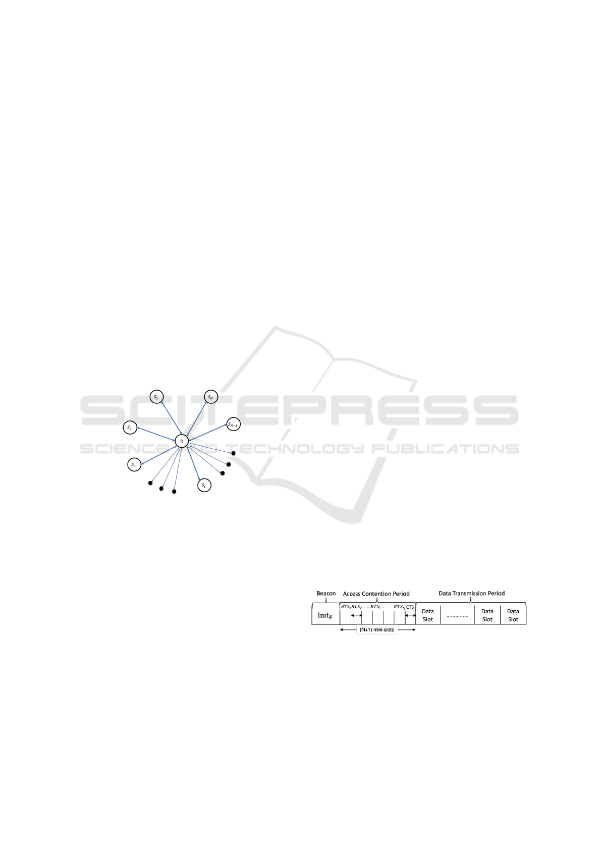
Figure 2: Star network topology.
In those atoms, we have N edge nodes
(S
1
,S
2
,S
3
,...,S
i
,...,S
N
) exchanging their data via a
central node called the relay node R. Such topology
can be useful in Satellite Networks, Access Point net-
works, Sensor Networks and Radio Access Network...
In order to improve the performance of the system
by using the NC (PNC) technique, we only have to
profit from the possible NC (PNC) scenarios in each
atom. In this work, we focus on the TWRC scenario
since its the simplest and the most frequent scenario
in the NC (PNC) domain. Remember that to profit
from the NC (PNC) technique, a MAC protocol is
needed to schedule the NC (PNC) transmissions and
to construct the NC (PNC) scenarios. Therefore, this
section presents a new proposed MAC protocol called
Dynamic Slotted Network Coding Protocol (DSNCP)
which is proposed for the atom level or the star topol-
ogy’s systems.
The basic idea of our proposal is to develop a
transmission scheduling in an opportunistic perspec-
tive so as to detect and prioritize network coding sce-
narios and, hence, improve the data throughput and
minimize the resulting delay.
In order to convey a basic understanding of the
protocol, basic assumptions and the fundamental pro-
tocol elements are explained:
1. internal clocks of all edge nodes are synchronized
to the relay node, not in absolute terms (i.e., so
that all stations share the same time) but such that
all nodes know exactly when a new time slot or
mini-slot starts and when it will end. The devel-
opment of an explicit synchronization scheme is
beyond the scope of this paper but we suggest ex-
istent proposals such as (Van den Bossche et al.,
2011; Huang et al., 2012; Chen et al., 2013; Liew
et al., 2015; Kramarev, 2016; You et al., 2016;
Kramarev et al., 2016; Hotescu et al., 2017).
2. the neighboring information is already given ei-
ther using hello messages (Krco and Dupcinov,
2003) or authentication and association tech-
niques (Roshan and Leary, 2004; Ganz and
Wongthavarawat, 1999; Athanasiou et al., 2007).
3. edge nodes have half-duplex links with the relay
node do not have links with each other.
4. all data packets have the same size so that nodes
will need the same duration or number of time
slots to transmit their data.
5. all the time-slots packets adhere to a fixed maxi-
mum size (which translates to a fixed transmission
duration less or equal to the time slot).
6. for design simplicity, we assume that the error-
correcting codes (Kwon and Shin, 2021) are used
to correct the corrupted packets so that acknowl-
edgments are no longer needed.
We consider a modified version of the TDMA pro-
tocol where time is divided into slots of unit length as
presented in Figure 3.
Figure 3: DSNCP Frame.
Each slot is divided into two parts: An access
Contention Period used for allocating resources and
a Transmission Period for data communications.
Dynamic Slotted Network Coding Protocol
583

3.1 Access Contention Period (ACP)
The access contention period is further divided into
(N + 1) mini-slots as shown in Figure 3, where N is
the number of relay’s neighbors (edge nodes). These
mini-slots are designed so as to support the traditional
RTS/CTS handshake for the allocation of the follow-
ing data transmission period. Such a mechanism will
help the relay node to detect NC/PNC opportunities
and make a better management of the data transmis-
sions.
Prior to each Access Contention Period, the re-
lay sends a super-frame Init
F
to trigger a new period.
This super-frame includes the type of the message
(Init
F
) which is in the frame control, the number of
mini-slots (NB
MS
), the allocation of each edge node
to its mini-slot (AF
MS
) and the Frame Check Sequence
(FCS) as shown in Figure 4 (a).
Figure 4: DSNCP Control Messages.
The starting time of the mini-slot (MS
i
) allocated
to the edge node N
i
could be computed using the for-
mula below:
MS
i
= t
0
+
i−1
∑
j=1
(MST
j
)( 1 ≤ i ≤ NB
MS
)
(1)
Where MS
i
is the start time of the i
th
mini-slot, t
0
is the starting time of the mini-slots phase, and MS
j
is
the duration of the j
th
mini-slot.
We have modified the RTS/CTS mechanism to
take into account the particularities of NC/PNC as fol-
lows:
In a given contention mini-slot, an edge node
wanting to send data sends first a Request To Send
frame (RTS) to the relay node. The RTS message, as
shown in Figure 4 (b), besides the type of the message
(contained in the Frame Control field) and the FCS,
contains Four fields: the node identifier (ID
S
), the pri-
ority (P) of the data to send, the relay node identifier
(ID
R
) and the final destination identifier (ID
F
).
When the relay receives all the RTS frames and
based on the adopted technique or system (NC or
PNC), it sends a NC or PNC Clear To Send frame
(CTS) in the (N + 1)
th
mini-slot to the sender nodes
allowing them to send their data in the following Data
Transmission period.
This CTS frame, as shown in Figure 4 (c), con-
tains: the type of the CTS message (CT S
NC
/CT S
PNC
)
(in the Frame Control field), the number of edge
nodes will send their data (NB
EN
) in this frame, the
number of time slots in the Data Transmission Period
(NB
T S
), the order of transmission of each sender (the
allocation of each node to its time slot) (AF
EN
)and the
FCS. In the AF
EN
section, each node’s ID will be fol-
lowed by his data slot number TS
i
.
Based on the received RTS frames, the relay can
easily detect and extract the TWRC scenarios versus
the ordinary scenarios and adapts the data transmis-
sion period allocation for that purpose.
In fact, for nodes forming an NC opportunity, the
relay provides three time slots: One for the first node’s
packet, one for the second node’s packet and the latter
for the relay to send the coded resulting packet. The
order is made with respect to the data priority so that
the first transmitting node is the one having the high-
est data priority. Whereas, for the PNC opportunity,
the relay provides two time slots: One for the first and
the second node’s packet and the latter for the relay to
send the coded PNC resulting packet.
On the other hand, the relay provides two-time
slots for each ordinary scenario so that the first time
slot is allocated for the ordinary node to send its data,
and the second is allocated for the relay to deliver the
ordinary data to the corresponding destination.
By sending the CT S frame, the Access Compe-
tition Period ends, and the Data Transmission Period
begins. We present details of this period’s functioning
in the next section.
3.2 Data Transmission Period (DTP)
In this phase, edge nodes will transmit their data to
the relay node, which will forward the received data
to each destination. After receiving the CT S frame,
each node could compute its starting time slot using
the formula below:
S
i
= t
0
+
i−1
∑
j=1
(DS
j
)( 1 ≤ i ≤ NB
MS
)
(2)
Where S
i
is the start time of the i
th
data slot, t
0
is
the starting time of the DTP, and DS
j
is the duration
of the j
th
data slot.
For further data packets, the edge nodes will wait
until they receive a new Init
F
super frame to initialize
a new DSNCP period.
ICSOFT 2022 - 17th International Conference on Software Technologies
584
The DSNCP flow graphs of the edge nodes and the
relay node respectively summarize the different steps
of the proposed solution and are presented by Figure
5 and Figure 6.
Figure 5: DSNCP flow graph for the edge nodes.
3.3 Illustrative Example
To illustrate the process of the proposed solution, we
refer to the example in Figure 7 in which five edge
nodes are exchanging data via a relay node. First,
the relay sends a message Init
F
to initialize a new pe-
riod. Based on the received Init
F
, each edge node that
wants to send data sends first an RT S message on its
mini-slot using equation 1.
Based on the received RTS frames, the relay node
detects data flows that can be combined on a NC/PNC
opportunity and ordinary ones. As mentioned in
the table 7 (b), the first NC/PNC scenario is formed
by transmissions of nodes N
1
and N
5
referred as
NCT (N
1
,N
5
), the second scenario in formed by trans-
missions of nodes N
2
and N
4
referred as NCT (N
2
,N
4
).
The flow of node N
3
will be relayed as an ordinary
traffic and referred as OT (N
3
).
Then, the Data Transmission Period will be di-
vided into eight data time slots using the NC ( six
time slots using the PNC) and scheduled with respect
to the priority of nodes involved in each transmission.
In this example, the priority of the NCT(N
1
,N
5
) is the
max(P
1
,P
5
) = 1, the priority of the NCT(N
2
,N
4
) is
the max(P
2
,P
4
) = 2 and the priority of the OT(N
3
)
Figure 6: DSNCP flow graph for the relay node.
Figure 7: Illustrative example.
is P
3
= 5. Hence the order of the transmissions is
as follows: the OT(N
3
) first, the NCT(N
2
,N
4
) second,
and finally, the NCT(N
1
,N
5
). When dealing with an
NC transmission, the node’s priority has no impact
on the two packets of the NC transmission since the
relay node will effectively deliver the coded frames
to each destination node at the same third-time slot,
but such priority is useful for the relay to schedule
transmission times. However, those priorities are very
Dynamic Slotted Network Coding Protocol
585

important for the order of the different NCT and OT
transmissions, since the higher the priority, the lower
the order of the NCT and OT transmissions, and the
lower the delay is.
Hence, after receiving the RTS frames and iden-
tifying all the NC/PNC opportunities, the relay node
broadcasts a CTS frame allowing concerned nodes to
send their data frames in their allocated time slots. As
shown in Figure 7 (c/d), this CTS frame contains: the
type of the message CT S
NC
/CT S
PNC
, the number of
edge nodes will send their data (NB
EN
) in this frame,
the number of time slots (NB
T S
) in DTP, the alloca-
tion of each edge node to its data time slot (AF
EN
)
and the FCS.
Based on the information contained on the CT S
frame, we can resume the scheduling details of the
NC DTP and PNC DTP as shown in Table 1 and 2,
respectively.
Table 1: Scheduling of the NC Data Transmission Period.
The node’s ID 1 2 3 4 5 R
Time Slot 6 3 1 4 7 (2,5,8)
Table 2: Scheduling of the PNC Data Transmission Period.
The node’s ID 1 2 3 4 5 R
Time Slot 5 3 1 3 5 (2,4,6)
Figures 8 and Figure 9, respectively, summarize
the NC and the PNC scheduling of the example 7
made by the DSNCP solution.
4 IMPLEMENTATION AND
RESULTS
This section presents the results of a simulation-based
performance evaluation of DSNCP and compares the
obtained results with a CSMA/CA and TDMA im-
plementation. For the well-known CSMA/CA and
TDMA MAC protocols, the NC opportunities are de-
tected by the relay depending on the queue of the re-
ceived data. If the relay detects an NC opportunity, it
encodes the two packets involved in this opportunity
and sends the encoded packet as an NC packet. We
first describe the simulation environment, the perfor-
mance metrics, and finally, we present and interpret
the obtained results.
Using NS-3 we implemented the CSMA/CA
NC
,
T DMA
NC
and DSNCP
NC
protocol. The system’s con-
figurations are presented in Table 3.
The performances of the proposed DSNCP are
evaluated using three metrics: the throughput, the
delay, and the packet loss rate, as these metrics are
closely impacted by the network coding paradigm.
The average throughput is measured in Kbits per
Table 3: Parameters used for the implementation.
Layer Parameter Value
Application
- Results obtained The average of 30 simulations
- Simulation time 200 seconds
- Distance between each edge node and the relay 300 meters
Network - routing protocol Static
Data Link
- Time Slot 0.8 millisecond
- Mini-slot’s time 20 microsecond
- Packet’s size 1024 bytes
- NC mapping technique XOR
Physical
- Physical standard DsssRate11Mbps
- Propagation loss model FriisPropagationLossModel
second and considers the average of the received bits
by all the edge nodes during the simulation period.
The formula for computing the throughput is:
T hroughput = (
∑
N
i=1
RCV DATA
i
N
) (3)
Where RCV DATA
i
is the amount of the received
data by the edge node i, and N is the number of edge
nodes.
The average end-to-end delay represents the to-
tal time to deliver a packet and includes all possible
delays caused by buffering, queuing at the interface
queue, re-transmission delay at the MAC layer, prop-
agation, and transfer time. It is expressed in millisec-
onds and is measured by the formula below:
Delay =
∑
P
j=1
(DT
j
−CT
j
)
P
k
(4)
Where (DT
j
− CT
j
) is the end-to-end delay of
packet j, which is the duration between the creation
time of the packet j by the sender (CT
j
) and its de-
livery time by the final destination (DT
j
), and P
k
is
the number of all the received packets by all the edge
nodes.
Finally, the third metric is the packet’s loss rate
(PLR), which represents the ratio of successfully re-
ceived packets (SRP) from all transmitted data pack-
ets (TDP). Since in our simulation we assume a per-
fect physical layer, where packets cannot be lost due
to the physical medium, we consider that all lost pack-
ets are dropped by the MAC or the NC queues. The
formula for computing the PLR is:
PLR % =
(SRP ∗ 100)
T DP
(5)
Simulation results are given, respectively, by
Figure 10 when varying the network density i.e
the number of edge nodes (we used topologies of
2,4,6,8,12,16 and 20 nodes) and Figure 11 when
varying the traffic load i.e the number of packets sent
by each edge node (we used a traffic pattern of 1000,
2000, 3000, 4000, 5000 and 6000 packets/node,
and whatever the traffic load, the production of the
packets is regular).
ICSOFT 2022 - 17th International Conference on Software Technologies
586

Figure 8: The NC DSNCP scheduling of the example presented in Figure 7.
Figure 9: The PNC DSNCP frame of the example presented in Figure 7.
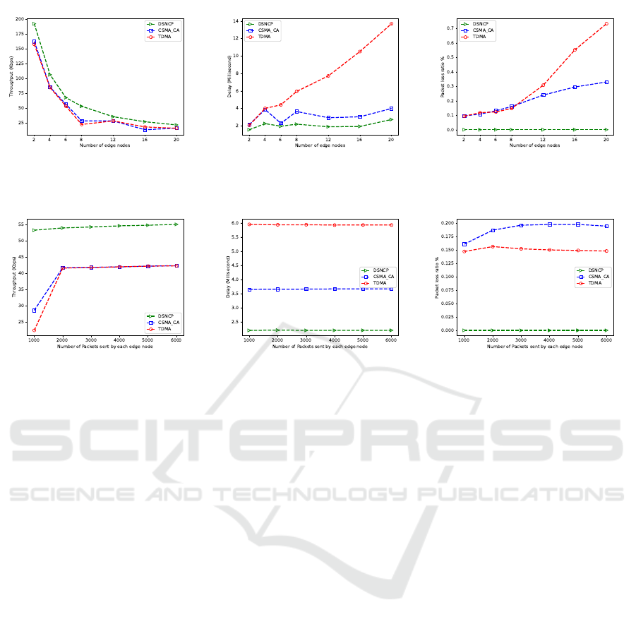
For the throughput, figures 10 (a) and 11 (a) show
that the DSNCP always outperforms the CSMA/CA
and the TDMA MAC protocols regardless of the
nodes number and the traffic load. It maintains a good
throughput longer because of its opportunistic nature
and its capacity to detect, beforehand, all the possible
NC opportunities for all the data flows compared to
the CSMA/CA and TDMA MAC protocols.
Furthermore, compared to CSMA/CA protocol
where medium access is made in a completely ran-
dom manner and compared to TDMA standard where
time slots are allocated to edge nodes in a static way
and therefore, the detection of NC opportunities is
rare and sometimes impossible, the centralized and
the dynamic aspects of our protocol DSNCP made
the medium access control easy and the scheduling
of data flows adaptive and efficient.
Moreover, the throughput is highly affected by the
forwarding MAC queue of the relay (the MAC queue
of the received packets from the edge nodes to for-
ward by the relay) and the NC queue, which is used
to store the NC packets for the relay and the sent pack-
ets, which used to decode the NC packets for the edge
nodes. Compared to our protocol, where the maxi-
mum required size of the forwarding MAC queue or
the NC queue is 2 (for the two packets of the two edge
nodes involved in the TWRC scenario).
Figure 10 (a) also shows that the throughput de-
creases gradually with the number of edge nodes.
This decrease is due to the processing delays and
losses caused by queue saturation at the relay node,
which increases with the affluence of new data pack-
ets.
We also note, from that figure 10 (a), that, for rel-
atively dense topologies (more than 12 nodes), the
CSMA/CA protocol slightly loses its efficiency in
terms of throughput compared to the TDMA protocol
because of the losses associated with medium access
and interference problems when dealing with several
nodes which are avoided in deterministic and slotted
access.
From figure 11 (a), we can see that all the proto-
cols are stable over time which is due to the regular
production of the data packets. Whenever the amount
of data is transmitted, the DSNCP outperforms in
terms of throughput. Also, we can see that CSMA/CA
Dynamic Slotted Network Coding Protocol
587
(a) Throughput. (b) Delay. (c) Packet’s Loss.
Figure 10: The performance results depending on the network density.
(a) Throughput. (b) Delay. (c) Packet’s Loss.
Figure 11: The performance results depending on the traffic load.
and TDMA protocols give almost the same through-
put in the same topology over time. Also, there is a
jump in the beginning for TDMA and CSMA/CA be-
cause of the small traffic load where there are a few
NC opportunities. Therefore the throughput will be
low compared with a high traffic load where there are
more NC opportunities.
For the delay results, depicted in figures 10 (b) and
11 (b), we can clearly observe the notable gain made
by DSNCP compared to other protocols. In fact, since
the NC decision in CSMA/CA and TDMA protocols
are based solely on data packets already received by
the relay node, this gives an advantage to our oppor-
tunistic solution to detect more opportunities, to re-
duce the time slots needed for each TWRC scenario
and thus to achieve better overall performance, partic-
ularly in terms of delivery delay.
From Figure 10 (b), if the number of edge nodes
increases, the delay of the DSNCP and CSMA/CA
is either constant or increased by a tiny percent-
age, compared to the TDMA protocol, which gives
the worst delay and increases exponentially with the
number of edge nodes.
The results in 10 (b) also show that, for all MAC
protocols, the end to end delay increases with the size
of the network, because, in general, increasing the
number of nodes in the network results in a further
traffic load and thus, the delays caused by buffering
delays and queues at the relay node contribute signif-
icantly to the end to end delay.
This increase is particularly significant with the
TDMA protocol, which could be explained by the
static time slot allocation and the presence of time
slots allocated uselessly to nodes that do not have data
to transmit.
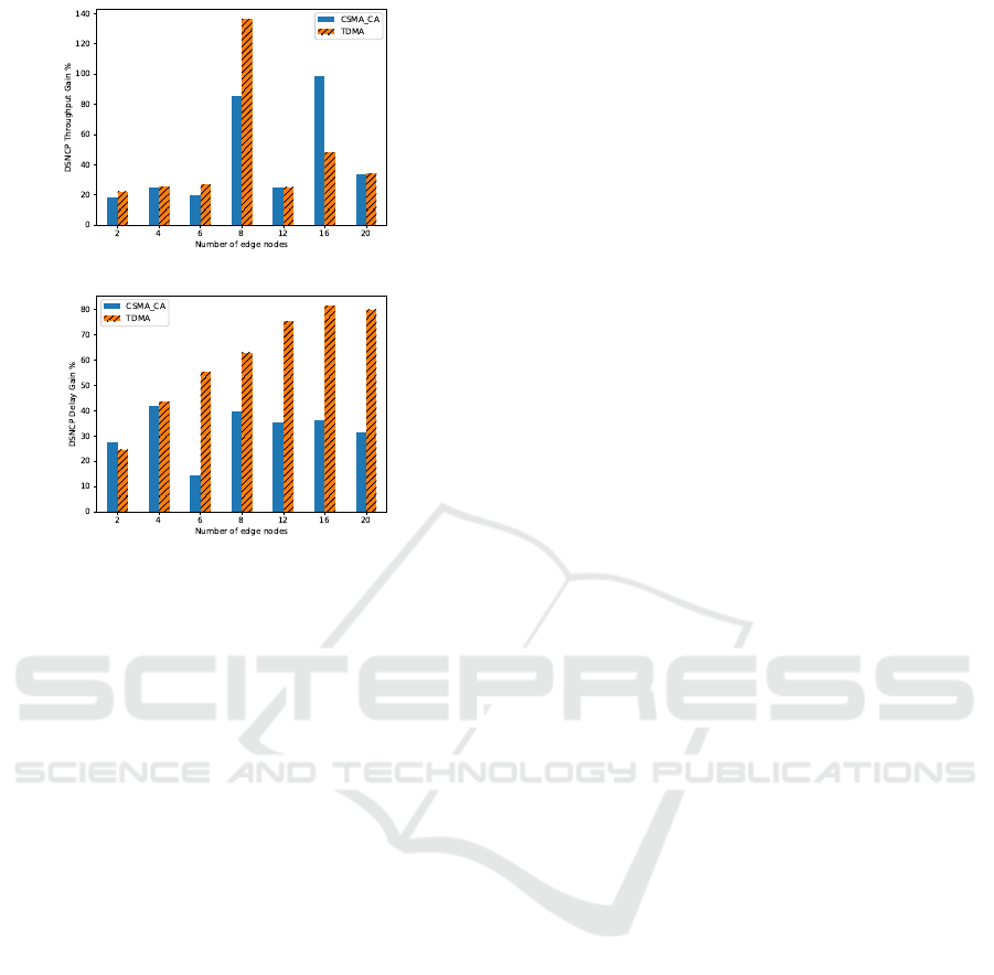
Figure 12 shows the gain of the DSNCP compared
to CSMA/CA and TDMA protocols in terms of, re-
spectively, throughput and end-to-end delay.
Figures 10 (c) and 11 (c) present the packet loss
ratio depending on the network density and the traffic
load, respectively. Since the DSNCP is based on a
prior handshake mechanism and the received packets
are directly followed in the next time slot by the relay,
it is generally rare to drop packets due to the fullness
of MAC queues or timeout. Hence, when, in addition,
considering a perfect physical medium, the packet’s
loss ratio of the DSNCP is naturally very low.
From results in figure 10 (c), we can conclude that,
since TDMA is static, the more the number of edge
nodes is, the more the received packets are, which can
lead to a fast saturation of queues and packet timeout.
Losses in CSMA/CA context are generally caused by
collisions at the access contention period.
From all the results, we conclude the performance
and the stability of the DSNCP over the CSMA/CA
and the TDMA MAC protocols in terms of through-
put, delay, and packet loss rate.
ICSOFT 2022 - 17th International Conference on Software Technologies
588
(a)
(b)
Figure 12: The DSNCP’s Delay and Throughput gains com-
pared to TDMA and CSMA/CA protocols.
5 CONCLUSION
In this paper, a dynamic slotted MAC protocol
(DSNCP) based on the well-known TDMA standard
has been proposed. DSNCP is designed to oppor-
tunistically support network coding TWRC scenar-
ios with a prior adapted handshake mechanism. The
proposed DSNCP introduces mini-time-slots in which
the relay node detects the TWRC opportunities and
schedules these transmissions in an efficient dynamic
way. By simulation under different network density
and traffic load patterns, we have demonstrated that
the DSNCP can substantially enhance the through-
put and the delay compared to the IEEE 802.11
CSMA/CA and TDMA based MAC protocols.
An ongoing experimentation of our solution is
performed on a real testbed based on Software De-
fined Radio technique which would validate this pri-
mary work and studies its feasibility in real large
wireless networks.
In future work, we also intend to propose a dis-
tributed and restriction-free medium access schedul-
ing making the DSNC solution more adapted for
larger wireless networks.
REFERENCES
Ahlswede, R., Cai, N., Li, S.-Y., and Yeung, R. W. (2000).
Network information flow. IEEE Transactions on in-
formation theory, 46(4):1204–1216.
Aissaoui, M., Houaidia, C., Van Den Bossche, A., Val,
T., and Saidane, L. A. (2021). A new taxonomy of
physical-layer network coding techniques in two way
relay channel model with single antenna. In 2021 10th
IFIP International Conference on Performance Eval-
uation and Modeling in Wireless and Wired Networks
(PEMWN), pages 1–6. IEEE.
Argyriou, A. (2012). Mac protocol for wireless cooper-
ative physical-layer network coding. In 2012 IEEE
Wireless Communications and Networking Confer-
ence (WCNC), pages 1596–1601. IEEE.
Athanasiou, G., Korakis, T., Ercetin, O., and Tassiulas, L.
(2007). Dynamic cross-layer association in 802.11-
based mesh networks. In IEEE INFOCOM 2007-26th
IEEE International Conference on Computer Commu-
nications, pages 2090–2098. IEEE.
Chen, Y., Haley, D., and Nguyen, Q. B. (2013). Frequency
offset compensation in physical-layer network coding
systems. In 2013 Australian Communications Theory
Workshop (AusCTW), pages 146–151. IEEE.
Committee, I. C. S. L. M. S. et al. (1999). Wireless lan
medium access control and physical layer specifica-
tion. IEEE 802.11 Standard.
De Oliveira, R. M., Vieira, L. F. M., Vieira, M. A. M., and
Vieira, A. B. (2021). A dynamic network coding mac
protocol for power line communication. Telecommu-
nication Systems, 77(2):359–375.
Fragouli, C., Le Boudec, J.-Y., and Widmer, J. (2006). Net-
work coding: an instant primer. ACM SIGCOMM
Computer Communication Review, 36(1):63–68.
Ganz, A. and Wongthavarawat, K. (1999). Ieee 802.11
wireless lan association procedure for multimedia
applications. In MILCOM 1999. IEEE Military
Communications. Conference Proceedings (Cat. No.
99CH36341), volume 2, pages 1287–1291. IEEE.
Gao, F., Xu, K., Zhang, D., and Xu, Y. (2014). Wireless
network coding via mac/phy: Design and implemen-
tation on usrp. In 2014 IEEE International Wireless
Symposium (IWS 2014), pages 1–4. IEEE.
He, J. and Liew, S.-C. (2015). Building blocks of physical-
layer network coding. IEEE Transactions on Wireless
Communications, 14(5):2711–2728.
Hoang, Q., Xuan Nam, T., and Nguyen, L.-T. (2015).
Cross-layer design of bidirectional-traffic supported
cooperative mac protocol. In International Confer-
ence on Advanced Technologies for Communications,
volume 2015, pages 586–593. IEEE Computer Soci-
ety.
Hoang, Q. T. (2020). Phy-mac cross-layer cooperative pro-
tocol supporting physical-layer network coding.
Hotescu, O., Jaffr
`
es-Runser, K., Van Den Bossche, A.,
and Val, T. (2017). Synchronizing tiny sensors with
sisp: a convergence study. In Proceedings of the 20th
ACM International Conference on Modelling, Analy-
Dynamic Slotted Network Coding Protocol
589

sis and Simulation of Wireless and Mobile Systems,
pages 279–287.
Huang, Y., Song, Q., Wang, S., and Jamalipour, A. (2012).
Phase-level synchronization for physical-layer net-
work coding. In 2012 IEEE Global Communications
Conference (GLOBECOM), pages 4423–4428. IEEE.
Kramarev, D. (2016). Practical physical layer network cod-
ing. PhD thesis, Monash University.
Kramarev, D., Sakzad, A., and Viterbo, E. (2016). Imple-
mentation of a two-way relay network with compute-
and-forward in gnu radio. Transactions on Emerging
Telecommunications Technologies, 27(4):484–493.
Krco, S. and Dupcinov, M. (2003). Improved neighbor
detection algorithm for aodv routing protocol. IEEE
Communications Letters, 7(12):584–586.
Kwon, S. and Shin, D.-J. (2021). Blind classification
of error-correcting codes for enhancing spectral effi-
ciency of wireless networks. IEEE Transactions on
Broadcasting, 67(3):651–663.
Lam, S. (1977). Delay analysis of a time division multiple
access (tdma) channel. IEEE Transactions on Com-
munications, 25(12):1489–1494.
Liew, S. C., Lu, L., and Zhang, S. (2015). A primer on
physical-layer network coding. Synthesis Lectures on
Communication Networks, 8(1):1–218.
Liew, S. C., Zhang, S., and Lu, L. (2013). Physical-layer
network coding: Tutorial, survey, and beyond. Physi-
cal Communication, 6:4–42.
Mao, W., Wang, X., Tang, A., and Qian, H. (2016). Anc-era:
Random access for analog network coding in wireless
networks. IEEE Transactions on Mobile Computing,
15(01):45–59.
Naves, R., Jakllari, G., Khalife, H., Conan, V., and Beylot,
A.-L. (2019). When analog meets digital: Source-
encoded physical-layer network coding. Pervasive
and Mobile Computing, 58:101021.
Roshan, P. and Leary, J. (2004). 802.11 Wireless LAN fun-
damentals. Cisco press.
Sadek, A. K., Su, W., and Liu, K. R. (2007). Multinode co-
operative communications in wireless networks. IEEE
Transactions on Signal Processing, 1(55):341–355.
Samarasinghe, K. (2011). Network coding with limited
overhearing in wireless sensor networks.
Shengli, Z., Liew, S.-C., and Lam, P. P. (2007).
Physical layer network coding. arXiv preprint
arXiv:0704.2475.
Silveira, L., Oliveira, R. M., Ribeiro, M. V., Vieira, L. F.,
Vieira, M. A., and Vieira, A. B. (2016). Codeplc: A
network coding mac protocol for power line commu-
nication. In 2016 IEEE 41st conference on local com-
puter networks (LCN), pages 643–646. IEEE.
Van den Bossche, A., Val, T., and Dalce, R. (2011). Sisp: a
lightweight synchronization protocol for wireless sen-
sor networks. In ETFA2011, pages 1–4. IEEE.
Wang, S., Song, Q., Wang, X., and Jamalipour, A. (2013).
Distributed mac protocol supporting physical-layer
network coding. IEEE Transactions on Mobile Com-
puting, 5(12):1023–1036.
Worlanyo, E. (2016). Network coding for wireless applica-
tions: A review.
Yang, J., Shen, X., Cheng, X., and Yang, L. (2014). Full
space-time network code. In 2014 Sixth International
Conference on Wireless Communications and Signal
Processing (WCSP), pages 1–6. IEEE.
Yomo, H. and Maeda, Y. (2011). Distributed mac protocol
for physical layer network coding. In 2011 The 14th
International Symposium on Wireless Personal Multi-
media Communications (WPMC), pages 1–5. IEEE.
You, L., Liew, S. C., and Lu, L. (2016). Reliable
physical-layer network coding supporting real appli-
cations. IEEE Transactions on Mobile Computing,
16(8):2334–2350.
Zhang, S., Liew, S. C., and Lam, P. P. (2006). Hot topic:
Physical-layer network coding. In Proceedings of the
12th annual international conference on Mobile com-
puting and networking, pages 358–365.
Zhou, Q. F., Zhao, L., Peng, M., Liu, X., and Fan, L. (2018).
Tdma-based cooperative nc mac scheme for two-way
relaying networks. IEEE Access, 6:7123–7133.
Zhu, F., Zhang, C., Zheng, Z., and Farouk, A. (2021). Prac-
tical network coding technologies and softwarization
in wireless networks. IEEE Internet of Things Jour-
nal, 8(7):5211–5218.
ICSOFT 2022 - 17th International Conference on Software Technologies
590
