
A Geometric Approach for Partial Liquids’ Pouring from a Regular
Container by a Robotic Manipulator
Jeeangh Jennessi Reyes-Montiel
a
, Antonio Marin-Hernandez
b
and Sergio Hernandez-Mendez
c
Artificial Intelligence Research Institute, Universidad Veracruzana, Calle Paseo No. 112, Xalapa, Mexico
Keywords:
Partial Liquids Pouring, Autonomous Mobile Robots, Geometric Control.
Abstract:
Partial liquid pouring is a very useful task in many environments; however, it is still a very challenging task for
autonomous mobile robots. In this work, is presented a geometric approach to accurately partial pouring by
autonomous robots. While diverse approaches propose to deal with this problem measuring liquid’s volume at
destination container, in this work is analyzed the geometry and initial volume of liquid at pouring container,
i.e., liquid’s volume and container characteristics are known. Then based on the transversal sections volumes’
is proposed to control pouring. Proposed approach computes the cross-section areas formed by liquid in the
container when this is tilted an angle θ. The geometric analysis shows that an angle-based linear control does
not guarantee a regular flow to perform an accurate liquid control, since cross-sectional volumes have not linear
relation with the angle θ when tilted. As it is show in this work, these volumes increase and decrease according
to the tilted angle and the container characteristics. To effectively obtain a regular flow those volumes should
be considered in the control phase as here is proposed.
1 INTRODUCTION
Many abilities on autonomous mobile robots and par-
ticularly on service robots have been implemented
and developed over last years. Nowadays, au-
tonomous and service robots can realize diverse tasks
on many different environments in a very successful
way. Mobile robots can: mapping their environments,
determine and execute trajectories, avoid fixed and
moving obstacles, detect, recognize, and interact with
users or other systems, and manipulate correctly di-
verse objects; all these very important and required
tasks for successful service robots. However, and de-
spite of robots can effectively pour liquids from one
container to other, generally this task is done in very
controlled environments and pouring the complete or
fixed amount of liquid. The pouring of partial and
varying quantities of liquids is still a challenging task
for service robots.
To successfully perform this task, most ap-
proaches require the detection and monitoring liquid’s
level, process generally done at destination container.
The problem lies mainly due to the different geome-
a
https://orcid.org/0000-0003-3194-914X
b
https://orcid.org/0000-0002-7697-9118
c
https://orcid.org/0000-0001-9997-9690
tries of the containers, great variety of liquids and par-
ticularly by the intrinsic characteristics of them (Do
and Burgard, 2019). This task, generally solved by
humans by reinforcement learning, is very important
in many human environments; so particularly, robots
and service robots should have the ability to deal with
it. Moreover, in such environments, humans often
don’t specifically make precise measurements of the
liquids they wish pour; for it, sometimes they use the
relation to some containers e.g., a cup or a glass for
measure a specific amount of liquid (Schenck and
Fox, 2017). Or, on the other hand, people usually use
subjective and undefined measures, which are gener-
ally mentioned in expressions such as: “pour me a
little more than half a cup of coffee” or “just a little
bit, please”. Humans can deal with language inaccu-
racies and are sufficiently able to learn complex tasks
as partial pouring of fluids.
Solving such a task requires a robust motion con-
trol, as well as a very accurate liquids characteris-
tics detection. However, for a robot, it is not easy to
carry out this task due to the complexity of fluids dy-
namics modeling (Schenck and Fox, 2017), (Pan and
Manocha, 2016).
In this work, is presented a special case of fluid
handling, specifically the problem of pouring a par-
ticular quantity of liquid from a known container to
688
Reyes-Montiel, J., Marin-Hernandez, A. and Hernandez-Mendez, S.
A Geometric Approach for Partial Liquids’ Pouring from a Regular Container by a Robotic Manipulator.
DOI: 10.5220/0011321600003271
In Proceedings of the 19th International Conference on Informatics in Control, Automation and Robotics (ICINCO 2022), pages 688-694
ISBN: 978-989-758-585-2; ISSN: 2184-2809
Copyright
c
2022 by SCITEPRESS – Science and Technology Publications, Lda. All rights reserved

another (unknown). To achieve this task a geometric
approach has been developed, which is supported on
a simplified hydro-dynamic model. To validate our
approach some tests on simulation environments are
presented.
This work is organized as follows. In next sec-
tion some important works related to the spill prob-
lem is described in the next section. Subsequently, in
section 3 it will be described the proposed geomet-
ric approach to solve the spillover problem. Then, in
section 4 presents the results obtained from the sim-
ulation. Finally, at section 5 the conclusions are pre-
sented.
2 RELATED WORKS
The problem of precise liquids’ pouring has become
very important in recent years There are many appli-
cations both industries and diverse sectors as: com-
merce or services.
For example, in metallurgy industry is a very com-
mon and important task, where it is required to main-
tain a constant flow to prevent oxidation, air entrap-
ment and erosion on metals (Noda and Terashima,
2006), (Noda and Terashima, 2007). To deal with
such problem in (Castilla et al., 2017) is presented
an approach to automate liquids pouring from a tilt-
ing ladle. Considering only the tilting ladle in mo-
tion, it is proposed to rotate the ladle at an angular
speed prescribed by a geometric and dynamic calcu-
lation to keep the discharge flow constant. To simplify
the geometry ladle is considered as a cylindric recip-
ient with circular weir. The resulting angular veloc-
ity was used as input for a set of computational fluid
dynamics simulations to later calculate the trajectory
of the spilled liquid. In (Sueki and Noda, 2019) it
is developed an improved model, initially proposed
in (Sueki and Noda, 2018), to pour molten metal in
a container by controlling the tilting ladle. The pro-
cess is achieved using a spill flow feedback control
to improve tracking performance. The discharge flow
rate is computed by using an extended Kalman filter
and controlled using a PID scheme. The proposed ap-
proach has been applied at laboratory with a pouring
robot.
Other approaches use physical models of simpli-
fied dynamics; for example, in (Pan and Manocha,
2016), is presented an approach using intrinsic prop-
erties of liquids to transfer them with a robotic ma-
nipulator from a container to another avoiding with
it, the high-cost solution of Navier-Stokes model. A
motion planning algorithm is then used to compute
a smooth and collision-free trajectory (Park et al.,
2012), (Ratliff et al., 2009), (Pan et al., 2016). The
simplified parameter set, and dynamic model is re-
stricted to the task of slow-rate liquid transfer. When
the end-effector is moves too fast, the motion de-
scribed could be far from planned trajectory. This ap-
proach pours the complete content of one recipient to
another.
To pour partial amounts of liquids, in (Do and
Burgard, 2019) it is proposed to control pouring liq-
uid level directly at destination recipient; for which,
authors propose, on one side to determine stoppage
using depth data from a low cost RGB-D camera and
on the other side, adapting pouring speed based on
liquid’s level at destination. With the use of an in-
frared light, authors overcome the problem of liquid’s
level detection for different transparency and refrac-
tive index of liquids like water, oil, or milk.
Spilled estimation is very important task when
pouring specific quantities. In (Matl et al., 2019) it
is proposed a method to pour liquids through haptic
sensing. In this work, initially a robot moves a con-
tainer through a series of tilting movements and ob-
serves the twists induced in the manipulator’s wrist
while the liquid’s center of mass scrolls. It is showed
that with haptic signals and a physics-based model it
can be obtained a high-precision estimate of liquids’
mass and volume in a cylindrical container. Addition-
ally, it is provided a framework for estimating fluid
viscosity.
The geometric characteristics of the container are
also important, for example in (Kennedy et al., 2017)
is proposed a method to autonomously dispense a pre-
cise amount of liquid using visual feedback. Authors
model diverse geometrical containers, showing that,
in particular for square base prisms the flow can be
controlled by observing the height of the fluid in the
receiving container. This approach to pouring control
is not smooth and calibration of the target container is
required.
Finally, in (Dong et al., 2019) are proposed two
approaches to control the movement of a service robot
as it accurately pours liquid from one unknown con-
tainer to another unknown container without the need
for external tools. The first proposal focuses on mea-
suring the height of poured liquid in the target con-
tainer. In this case, the action is controlled using a PD
controller, which considers the angular velocity of the
pouring vessel as a process variable and the volume
poured as a control variable. The second method fo-
cuses on the pouring container. The volume poured
is calculated using the relationship between the an-
gle of the pour container and discharged volume. The
action is controlled with a simple proportional con-
troller that takes the angular velocity of pouring vessel
A Geometric Approach for Partial Liquids’ Pouring from a Regular Container by a Robotic Manipulator
689
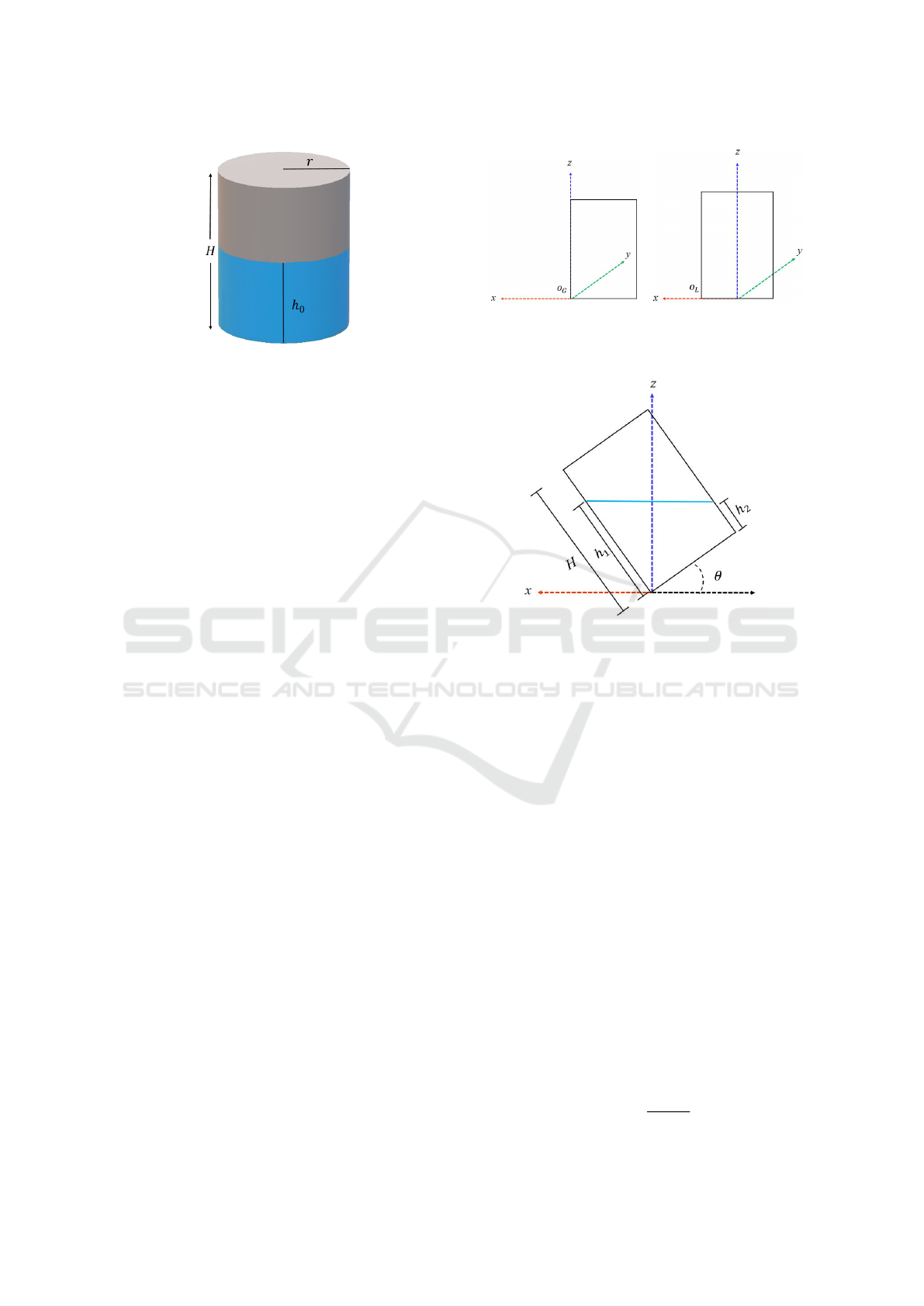
Figure 1: Initial assumptions: a known cylindrical container
with a known liquid of initial height h
0
.
as the process variable and target angle as the control
variable. For it, it is only used sensor inputs from an
RGB-D camera on the robot’s wrist. To perform the
tests, both methods are implemented in a double-arm
robot system and the results show that accurate pour-
ing is obtained in both methods.
This work focuses on pouring specific quantities
of liquids, through the analysis of the geometry of
pouring container particularly cylindrical containers.
Physical properties of liquids, such as laminar flow is
also considered. In such a way that smooth control be
achieved when pouring liquids. In next section, anal-
ysis of the geometric model will be described.
3 GEOMETRIC MODELING
In this section, the geometrical approach to model and
control partial pouring is presented. Following as-
sumptions are considered:
1. A cylindrical container of height H and radius r.
2. The initial liquid’s height inside the container is
h
0
.
3. Liquid’s density is considered known.
Therefore, the following statements can be stab-
lished. The robot always uses a known pouring con-
tainer. Initial volume of the liquid in the container
can be determined and this is considered known, e.g.,
water, milk or sirup. Additionally, robot is requested
to pour specific quantities of liquid, e.g., beginning
with 200ml and then 50ml. And finally, to be able to
compute precisely liquid poured, the pouring process
must ensure a laminar flow, in other words, the robot
should not do sudden motions to avoid turbulences.
3.1 Spilling Angles
Initial and final pouring angles can be easily deter-
mined by the problems geometry.
(a) (b)
Figure 2: References frames. a) Global reference frame and
b) local reference frame.
Figure 3: Cylinder with an inclination θ.
The total volume of the container is given by:
V
T
= πr
2
H,
and similarly, the initial volume of the liquid is
given by: V
init
= πr
2
h
0
.
As showed on Figure 2, two reference frames are
considered: a) the global reference frame, which by
simplicity is placed at the tilting corner of the con-
tainer and denoted by O
G
, and b) the local reference
frame placed at the bottom center of the container and
denoted by O
L
.
To find the spill angle θ
s
, it is necessary to analyze
the geometry and rotation around O
G
.
When container slopes an angle θ and the liquid
inside changes its shape (Figure 3), it can be verified
that:
1. Liquid’s height in the local reference frame O
L
is
composed by the average of two heights h
1
and h
2
,
corresponding to both sides of the cylindrical con-
tainer, where dh is the difference between them.
2. The form of liquid’s surface goes from a circle at
θ = 0 to an ellipse with major axis 2a at θ > 0.
Then, when h
1
= H liquids begins to spill and then
θ
s
can be determined by:
tanθ
s
=
H − h
0
r
. (1)
ICINCO 2022 - 19th International Conference on Informatics in Control, Automation and Robotics
690
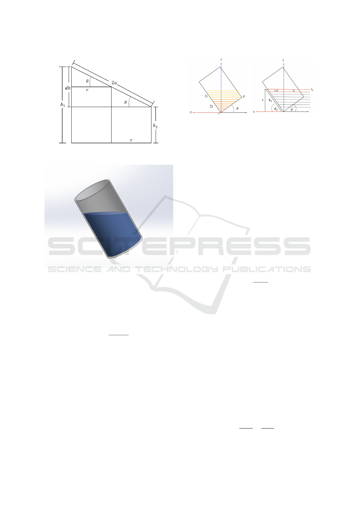
Figure 4: Geometric analysis of the shape acquired by liq-
uid when tilted at an angle θ.
Figure 5: Liquid surface visualization (surface ellipses for-
mation).
Similarly, to obtain the final spill angle θ
f
, it can
be determined considering the difference dV between
the liquid’s initial volume V
init
and poured volume V
P
,
then computing the corresponding height h
dV
, the an-
gle is given by:
tanθ
f
=
H − h
dV
r
. (2)
3.2 Transversal Sections Volumes
As described previously, in order to compute accu-
rately poured liquid’s volume is very important to get
to make a smooth control to avoid a turbulent flow.
It can be observed that the surface of the liquid
forms ellipses when it is inclined at an angle θ 6= 0.
And as showed in figure 6, two regions can be distin-
guished; the first region above the point P, in which it
can be seen that, ellipses formed are complete, and a
second region, below the point P, where it can be seen
that the ellipses are trimmed.
(a) (b)
Figure 6: Geometry considerations. a) Region 1 in yellow
and region 2 in orange, and in (b) Volume discretization.
3.2.1 Determination of the Transversal Volumes
at First Region
Being S
n
as the area of liquids’ surface as described
in Figure 6b, and considering a height discretization
into n similar intervals of height ∆l in the global ref-
erence frame, then it can be considered the volume of
a transversal section as:
V
n
= S
n
∆l (3)
where ∆l is related with liquid’s viscosity.
The total volume will be the sum of all transversal
volumes, as follows:
V
T
=
n
∑
i=1
V
i
(θ) =
∑
S
i
∆l = S
i
∆ln. (4)
It is important to note that, the volume of each
segment is a function of tilting angle, as following:
V
n
(θ) =
πr
2
∆h
cosθ
. (5)
3.2.2 Determination of the Volume at Second
Region.
Below point P and due to geometry of tilted container,
surfaces ellipses are incomplete as described in Fig.
8. Moreover, to determined transversal volumes be-
low point P, it is important to note there are two sub-
regions. One above O
L
and the other one below O
l
Remembering that, the last complete ellipse
formed will be at h
2
= 0 (this point is referenced as
P) as showed in Figure 7, then below this point, all el-
lipses formed will be cut in relation to the semi-major
axis, as shown in figure 8.
It is required to find the parameter a
c
that deter-
mines the cuts of these ellipses. Since a
c
cuts reduce
ellipses according to the semi-major axis, this value
will have a constant of proportionality being a
c
= α,
where α is:
α =
y
y
p
(θ)
=
y
rsinθ
(6)
A Geometric Approach for Partial Liquids’ Pouring from a Regular Container by a Robotic Manipulator
691
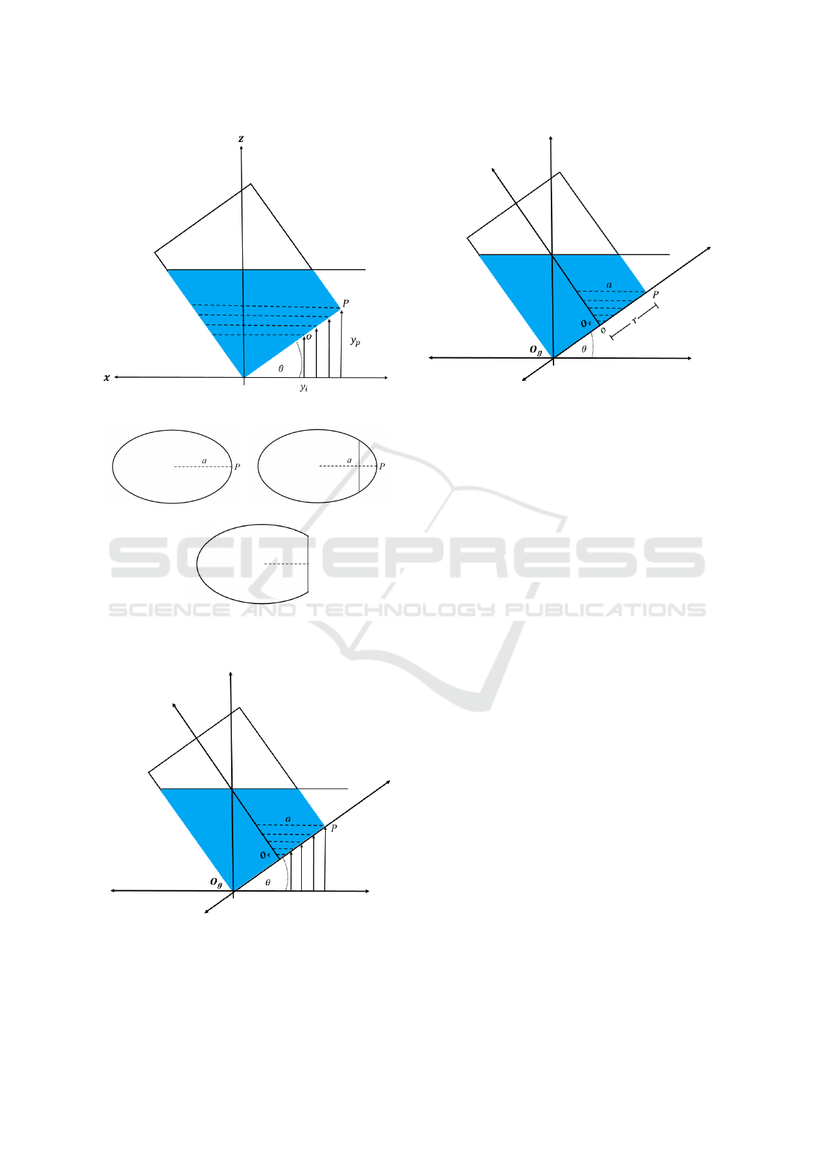
Figure 7: Ellipses cut below point P (o → r).
(a) (b)
(c)
Figure 8: Geometry cut: a) Complete ellipse, b) section to
cut and c) final area.
Figure 9: Geometry of the tilted container at the region r →
0.
where y is the height of the container from the base
of O
L
frame to an angle θ and assuming the following
Figure 10: Intervals from 0 to r.
condition y ≤ rsinθ.
Below point P, ellipses formed are not only cut,
but also deformed. This is due, particularly by the
implicit geometry of this section. At this stage of the
work, this subregion is not considered. So, a hard con-
straint is considered, and is that nor the initial liquid
volume nor the final volume is inferior to h < r.
From analysis of transversal sections, it can be
seeing that volumes increase until h
2
= 0, then vol-
umes of transversal sections decrease. Then, to get a
soft pouring it is required a function of these transver-
sal sections in order to get a regular flow and then
estimate accurately poured volume.
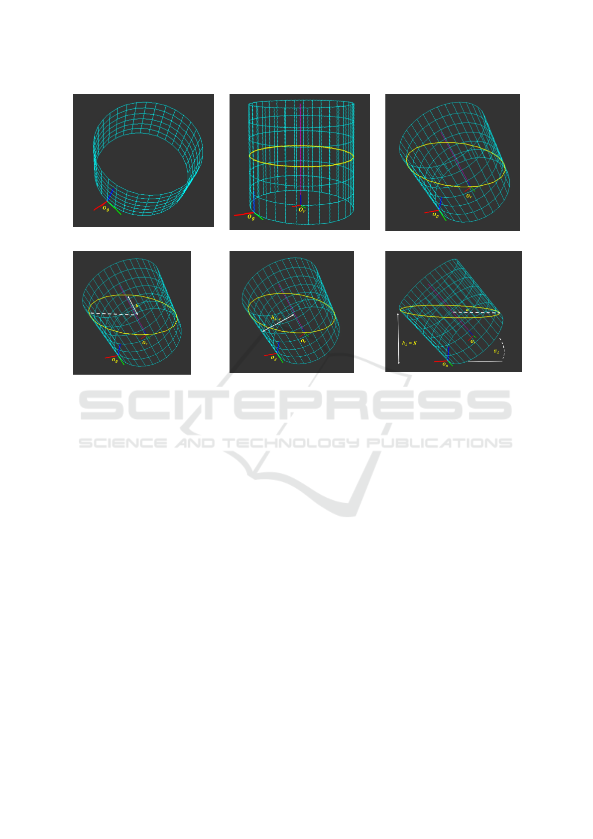
4 PRELIMINARY RESULTS
The proposed approach has been validated by per-
forming some tests over simulation environments, as
showed in Figure 11. As it can be seen, from figures
(b) to (f), at the first region, as it has been described in
section 3.2.1, the transversal section area increases in
function of the tilted angle. However, this relation is
not linear, thus the change in volume of correspond-
ing section is neither.
Moreover, at region two, the ellipses formed are
cut as it has been described previously; decreasing the
transversal section area while tilted angle increases,
thus volumes of corresponding sections also decrease.
Therefore, and considering a close relation be-
tween the volume of the cross section and the vis-
cosity, to get a regular flow, it is necessary to control
pouring according to volumes’ change of mentioned
sections.
ICINCO 2022 - 19th International Conference on Informatics in Control, Automation and Robotics
692
(a)
(b)
(c)
(d)
(e)
(f)
Figure 11: Simulation environments: a) cylindrical container, b) reference frames, c) elliptical liquid surface, d) semi-minor
and major axis at ellipse, e) height of the liquid, and f) initial pouring point.
5 CONCLUSION
In this work, a geometrical approach to pouring spe-
cific quantities of liquid was presented. The proposed
approach considers the variation of cross-sectional ar-
eas formed by the tilted container to control pouring.
Based on the geometry analysis exposed, it has been
showed that a linear angular control does not assure
a regular flow. Therefore, to get a regular flow it is
required to consider the two regions described, when
areas and corresponding volumes increase, at region
one, and when they decrease, at region two. It is im-
portant to note, that both regions occurs while θ angle
is increasing, proving that linear angular control is not
enough to get a regular flow.
In future works, experiments on real autonomous
robots will be done, considering different liquid’s vis-
cosity, quantities and diverse shape containers.
REFERENCES
Castilla, R., Gamez-Montero, P. J., Raush, G., Khamashta,
M., and Codina, E. (2017). Numerical study of im-
pingement location of liquid jet poured from a tilt-
ing ladle with lip spout. Metallurgical and Materials
Transactions B, 48(2):1390–1399.
Do, C. and Burgard, W. (2019). Accurate pouring with an
autonomous robot using an rgb-d camera. In Strand,
M., Dillmann, R., Menegatti, E., and Ghidoni, S., ed-
itors, Intelligent Autonomous Systems 15, pages 210–
221, Cham. Springer International Publishing.
Dong, C., Takizawa, M., Kudoh, S., and Suehiro, T. (2019).
Precision pouring into unknown containers by ser-
vice robots. In 2019 IEEE/RSJ International Confer-
ence on Intelligent Robots and Systems (IROS), pages
5875–5882.
Kennedy, M., Queen, K., Thakur, D., Daniilidis, K., and
Kumar, V. (2017). Precise dispensing of liquids us-
ing visual feedback. In 2017 IEEE/RSJ International
Conference on Intelligent Robots and Systems (IROS),
pages 1260–1266.
Matl, C., Matthew, R., and Bajcsy, R. (2019). Hap-
tic perception of liquids enclosed in containers. In
2019 IEEE/RSJ International Conference on Intelli-
gent Robots and Systems (IROS), pages 7142–7149.
Noda, Y. and Terashima, K. (2006). Nonlinear model-
ing with hydrodynamics and flow control using in-
verse pouring dynamics of tilting-ladle-type automatic
pouring process. In Proceedings of the 67th World
Foundry Congress, volume 207, pages 1–10.
A Geometric Approach for Partial Liquids’ Pouring from a Regular Container by a Robotic Manipulator
693

Noda, Y. and Terashima, K. (2007). Falling position con-
trol of outflow liquid for automatic pouring system
with tilting-type ladle. IFAC Proceedings Volumes,
40(11):53–58. 12th IFAC Symposium on Automation
in Mining, Mineral and Metal Processing.
Pan, Z. and Manocha, D. (2016). Motion planning for
fluid manipulation using simplified dynamics. In
2016 IEEE/RSJ International Conference on Intelli-
gent Robots and Systems (IROS), pages 4224–4231.
Pan, Z., Park, C., and Manocha, D. (2016). Robot motion
planning for pouring liquids. In ICAPS, pages 518–
526.
Park, C., Pan, J., and Manocha, D. (2012). Itomp: In-
cremental trajectory optimization for real-time replan-
ning in dynamic environments. In ICAPS.
Ratliff, N., Zucker, M., Bagnell, J. A., and Srinivasa, S.
(2009). Chomp: Gradient optimization techniques for
efficient motion planning. In 2009 IEEE International
Conference on Robotics and Automation, pages 489–
494.
Schenck, C. and Fox, D. (2017). Visual closed-loop control
for pouring liquids. In 2017 IEEE International Con-
ference on Robotics and Automation (ICRA), pages
2629–2636.
Sueki, Y. and Noda, Y. (2018). Operational assistance sys-
tem with direct manipulation of flow rate and falling
position of outflow liquid in tilting-ladle-type pouring
machine. In Proceedings of the 73rd World Foundry
Congress, Cracow, Poland, pages 23–27.
Sueki, Y. and Noda, Y. (2019). Development of flow rate
feedback control in tilting-ladle-type pouring robot
with direct manipulation of pouring flow rate. In
ICINCO.
ICINCO 2022 - 19th International Conference on Informatics in Control, Automation and Robotics
694
