
Switched-based Control Testbed to Assure
Cyber-physical Resilience by Design
Mariana Segovia
a
, Jose Rubio-Hernan
b
, Ana R. Cavalli
c
and Joaquin Garcia-Alfaro
d
T
´
el
´
ecom SudParis, Institut Polytechnique de Paris, France
Keywords:
Cyber-Physical Systems, Resilience, Testbeds, Cyber-physical Adversaries.
Abstract:
Cyber-Physical Systems (CPS) integrate control systems engineering, computer science, and networking to
control a physical process. The main challenge after detecting malicious actions in a CPS is to choose the
correct reaction that the system has to carry out. In this paper, we propose a deployment platform for cyber-
physical configurations evaluation to satisfy cyber-physical resilience properties. Experimental testbeds are
crucial to analyze new proposals. For this reason, we discuss some actions for the development of a replica-
ble and affordable cyber-physical testbed for training and research. The architecture is based on real-world
components. This solution combines diverse parameters that come from cyber and physical layers.
1 INTRODUCTION
Cyber-Physical Systems (CPS) integrate physical in-
frastructures, computing, and networking resources
to create more efficient control systems. These sys-
tems rely upon internally gathered information to per-
form correct, change or even stop actions. Traditional
networking and computing security approaches cover
cyber threats, but fail at addressing cyber-physical
threats. Also, CPS normally provide critical func-
tionalities. Hence, evaluation methods have to ensure
safety and test the system automation properly to pro-
vide correct behavior even under an attack when the
inputs are maliciously modified. For this reason, solu-
tions that combine control-theoretic with network and
computing security techniques can lead to powerful
solutions to cover both physical and cyber-physical
attacks at the same time.
In this paper we present an innovative and orig-
inal approach, which has been implemented in a re-
silient platform based on a programmable CPS. In
this environment, network and physical controllers
get connected toward coordinating resilience strate-
gies, for example, to maintain the resilient properties
of the system under failure and attacks. As a main
contribution, we provide an architecture combining
control-theoretic solutions with programmable net-
working techniques to jointly handle crucial threats
a
https://orcid.org/0000-0001-8343-1049
b
https://orcid.org/0000-0001-9778-8049
c
https://orcid.org/0000-0003-2586-9071
d
https://orcid.org/0000-0002-7453-4393
to CPS. Also, the CPS and network controller work
together to protect the system. The proposed deploy-
ment platform helps to evaluate cyber-physical re-
silience properties. To illustrate the application of our
approach, we propose a testbed based on a quadruple-
tank process (Johansson, 2000).
The remaining sections are structured as follows.
Section 2 presents related work. Section 3 pro-
vides our resilience approach. Section 4 presents the
blueprints of a testbed associated with our approach.
Section 5 concludes the paper.
2 RELATED WORK
The research community use experimental testbeds
as validation methods for new approaches. Testbeds
have the advantage of incorporating physical devices
such as sensors and actuators creating more realistic
scenarios. However, they are more expensive and nor-
mally the implemented system is simpler than in sim-
ulation scenarios. In the sequel, we present the main
testbed that have been used in the literature.
Firstly, the quadruple-tank process (Johansson,
2000) is a multivariable laboratory process consist-
ing of four interconnected water tanks that move the
water from one tank to another using pumps and level
sensors.
Another commonly used testbed is the Landshark
robot
1
, which is a fully electric unmanned ground ve-
1
https://www.blackirobotics.com/landshark-ugv/
Segovia, M., Rubio-Hernan, J., Cavalli, A. and Garcia-Alfaro, J.
Switched-based Control Testbed to Assure Cyber-physical Resilience by Design.
DOI: 10.5220/0011327300003283
In Proceedings of the 19th International Conference on Security and Cryptography (SECRYPT 2022), pages 681-686
ISBN: 978-989-758-590-6; ISSN: 2184-7711
Copyright
c
2022 by SCITEPRESS – Science and Technology Publications, Lda. All rights reserved
681
hicle. It has an onboard computer with a Linux sys-
tem running. The computer performs all tasks such
as PID control, LIDAR, GPS, IMU, and encoders.
Also based on unmanned vehicles, authors in (Rubio-
Hernan et al., 2016) propose a testbed based on Lego
Mindstorms EV3 bricks and Raspberry Pi boards as
PLCs to control some representative sensors (e.g., ul-
trasonic distance measurers) and actuators (e.g., speed
accelerators) using SCADA protocols such as Mod-
bus and DNP3 for the component communications.
For power grids systems, (Sanders, 2012) pro-
poses a cyber-physical testbed based on commercial
tools that combine emulation, simulation, and real
hardware to experiment with smart grid technologies.
Finally, the authors in (Koutsandria et al., 2015) im-
plement a real-time testbed for CPS security on power
grids, where the data are cross-checked using cyber
and physical elements.
3 SWITCHED-BASED
RESILIENCE CONTROL
3.1 Architecture Design
Most industry control systems are Multiple-Input-
Multiple-Output (MIMO) systems (Liu et al., 2019),
i.e., the process consists of several measurement and
control signals. There are often dependencies, called
couplings, between these variables (Garrido et al.,
2011). When designing the controllers for MIMO
systems, it is necessary to handle the given problem
into manageable subproblems. As a result, the overall
plant is no longer controlled by a single MIMO con-
troller but by several independent controllers which
altogether represent a distributed controller (Bakule,
2008). A distributed control consists of a set of in-
dependent controllers, typically Single-Input-Single-
Output (SISO) control loops, i.e., controllers that re-
ceive one input and return one control signal as out-
put.
Centralized controllers have better performance.
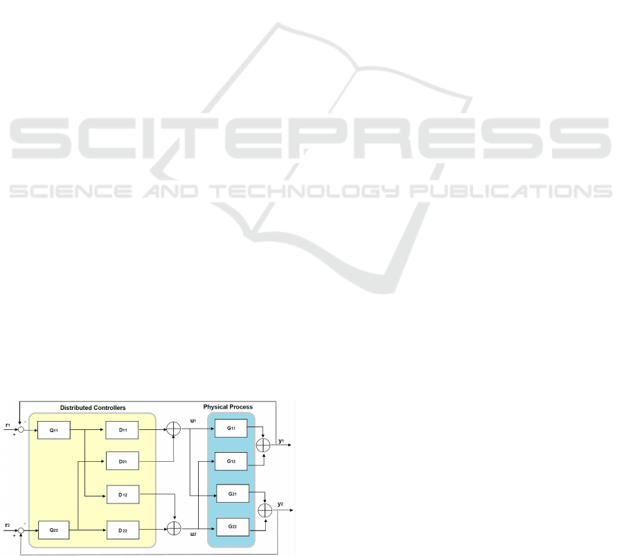
Figure 1: Distributed feedback controller topology.
However, distributed SISO control is often preferred
because it has several advantages such as they are eas-
ier to implement, the tuning is simplified and they are
more robust to model errors.
The design of such a control system introduces
the pairing problem which is concerned with defin-
ing the system structure, i.e., which of the available
plant inputs will be used to control each of the plant
outputs (Campo and Morari, 1994). For a fully non-
interacting plant, the choice is obvious. However, in
any practical problem, there are interactions in the
plant. This means that even if the control system is
distributed, subsystems of the closed-loop design are
not independent of each other.
For an n × n plant, there are n factorial (n!) pos-
sible SISO pairings to chose and each controller has
only available a part of the overall a priori and a pos-
teriori information. Most of the decoupling control
synthesis strategies firstly compute a decoupling pre-
compensator (called Decoupler) to turn the resultant
system into a more nearly diagonal transfer matrix as
showed in Figure 1. These aforementioned system
properties allow having many possible implementa-
tions for the same system. We use it to implement an
approach to improve system resilience.
3.2 Switched-control Systems
To improve the system resilience, we model our phys-
ical process as a switched linear system. Switch-
ing control techniques are based on changing be-
tween different controllers in an adaptive context
while achieving stability. Switched systems with all
the subsystems described by linear differential equa-
tions are called switched linear systems.
Many systems encountered in practice exhibit
switching between several subsystems that are depen-
dent on various environmental factors. For example,
in a car, the first, second, and third gears experiment
different dynamics that can be modeled using differ-
ent controller models. In particular, switched sys-
tems have gained major attention in the control the-
ory community in the last years since there exist un-
stable processes that are not possible to control with
just one model, but it is possible to design switched
controllers for stabilizing it with piece-wise signals
(Decarlo et al., 2000)
3.3 System Model
Our approach aims at protecting the system from net-
work adversaries working at the network layers mod-
ifying the endpoint information and at the node level
by modifying the controller model. To achieve that,
SECRYPT 2022 - 19th International Conference on Security and Cryptography
682

the system design uses a distributed architecture of
controllers and calculates the system feedback using
a model based on Switched Linear Control. This way,
the model is represented as a Linear Time-Variant
(LTV) system. A switched system consists of a finite
number of subsystems and a logical rule that orches-
trates the switching between the subsystems. It may
be modeled as follows:
x
k+1
= f
σ(k)
(x
k
, u
k
) (1)
where k ∈ Z
+
is the time interval, x ∈ R
n
is the state,
u ∈ R
p
is the control input and σ is the logical rule
that orchestrates the switching between the subsys-
tems. It means that σ is a function σ : Z
+
→ I, where
I = {1, ..., N} contains the indexes of the subsystems.
A subsystem is determined by a pair (M
i
, G
i
) where
M
i
= {A
i
, B
i
, C
i
: i ∈ I } is the set of physical system
models and G
i
= {V
i
, E
i
: i ∈ I } is the set of graphs
that represent the network connections in the CPS.
Hence, σ defines a piece-wise switching signal that is
a time-varying definition of the process model and the
network graph that is activated at time k. The physical
model activated at time k is defined as follows:
x
k+1
= A
σ(k)
x
k
+ B
σ(k)
u
k
y
k
= C
σ(k)
x
k
(2)
where x
k
and u
k
are equal to the previous equation and
w
k
∈ R
n
is the process noise that is assumed to be a
zero-mean Gaussian white noise with covariance Q,
i.e. w
k
∼ N(0, Q). Moreover, A ∈ R
n×n
and B ∈ R
n×p
are respectively the state matrix and the input matrix.
The value of the output vector y
k
∈ R
m
represents the
measurements produced by the sensors that are af-
fected by a noise v
k
assumed as a zero-mean Gaussian
white noise with covariance R, i.e. v
k
∼ N(0, R) and
C ∈ R
m×n
is the output matrix that maps the state x
k
to the system output.
The overall process is controlled by several in-
dependent controllers and altogether represent a dis-
tributed controller. The feedback controller topology
for a 2x2 system (i.e., with two inputs and two out-
puts) is showed in Figure 1. The controllers take one
input and send one output. Each of them will be ex-
ecuted in one node. All the executed system models
are equivalent and they are obtained applying factor-
ization matrices techniques similar to the ones used
by the different approaches for distributed control de-
sign (Liu et al., 2019).
The dynamics of the physical process are ex-
pressed by a transfer function G that we obtained from
(Johansson, 2000). The controller topology is based
on the matrices Q and D which correspond respec-
tively to the diagonal transfer function and the de-
coupler (Segovia-Ferreira et al., 2020). This way, the
process dynamics are expressed using a set of inde-
pendent processes as shown next:
G(s) · D(s) = Q(s) (3)
To create the set of distributed model designs, i.e.,
the set of matrices D(s) and Q(s), the first step is to
calculate ad jG(s) the adjudged matrix of G which is
the transposition of the co-factor matrix of G. Then,
we build matrix D(s) as follows. For each column
ˆ
J = {1, .., N}, we select a row
ˆ
I to set that element d
ˆ
I
ˆ
J
in the matrix D(s) to unity. It is necessary to choose
one for each column but not necessarily the diagonal
ones.
After choosing the elements (
ˆ
I,
ˆ
J) to be set to one,
the matrix D(s) can be completed as follows:
d
i
ˆ
J
=
ad jG
i
ˆ
J
ad jG
ˆ
I
ˆ
J
where i varies from 1, .., N with i 6=
ˆ
I and ad jG
i
ˆ
J
is
the (i,
ˆ
J) element of ad jG(s) the adjugate matrix of
G. This means that for each column in the matrix,
ˆ
J
is fixed and it corresponds to the column where the
value was set to one previously. Hence, each ele-
ment d
i
ˆ
J
is obtained from dividing the element (i,
ˆ
J) in
the ad jG(s) matrix between the value in the position
(
ˆ
I,
ˆ
J) of the matrix ad jG(s).
We have to repeat this process for each column by
fixing a new
ˆ
J to obtain the complete matrix D(s) cor-
responding to one single model. After we obtained
the complete matrix D(s), we repeat the whole pro-
cess by selecting a different row
ˆ
I to obtain another
model different from the previous one.
Finally, Q(s) is a diagonal matrix built using
Equation (3) and multiplying G(s) · D(s). Each ma-
trix D(s) gives, as a result, a different matrix Q(s). In
addition, each entry of matrices D(s) and D(s) corre-
spond to the transfer function of one controller.
3.4 Resilience Orchestrator
To coordinate the resilience, there is an orchestrator,
physically located within the SDN Controller. The
responsibilities of the orchestrator are detailed next.
Model Selection and Transformation Time —
There are I = {1, ..., N} possible subsystems to ac-
tivate and the orchestrator chooses randomly a key K
1
which will be used to select the next model to activate
using a hash function as follows hash(K
1
, j) mod N
where j is the switching interval. The common shar-
ing of K
1
, j and N allows each device to compute the
next active model in a distributed manner. The key
is renewed periodically using one of the existing ap-
proaches for key generation and distribution such as
(Kumari and Anjali, 2018).
Switched-based Control Testbed to Assure Cyber-physical Resilience by Design
683

In addition, the orchestrator has to choose and
coordinate the switching in a master-slave mode. For
that, it requires a distributed timing synchronization,
such as (Sivrikaya and Yener, 2004) to ensure the
maintenance of a common time for all the nodes of
the network.
Coordinating the Network Configuration Trans-
formation — Each component will change its net-
work configuration in each switching period of the
physical model. To do this, each device gets a real
IP address (RIPA) and a virtual IP address (VIPA).
The RIPA is used for management purposes making
the network configuration transformation transparent
to administrators. The VIPA is used to communicate
the data packets of the CPS, i.e., the hosts commu-
nicate with another host using their VIPAs. In ad-
dition, VIPAs change periodically and synchronously
in a distributed fashion over time. In every transfor-
mation interval, the hosts will be associated with a
unique VIPA.
The VIPA transformation is managed by the SDN
devices by selecting an address from the unused ad-
dress space. Each host will be allocated an IP address
ranges to choose the VIPAs and they are selected us-
ing a hash function from the designated ranges. Since
the VIPAs are chosen from the assigned network sub-
nets, there is no need to do a routing update advertise-
ment for internal routers. In addition, SDN devices
will forward packets from old connections until the
session is terminated or expired.
Each SDN device is responsible for the manage-
ment of the hosts in one or more subnets. The VIPAs
selection is done in a similar way to the physical
model selection. It uses a hash function and a secret
random key to guarantee unpredictability. If there are
p available VIPAs for a host, then the SDN device can
compute the index of the VIPA for the switching in-
terval j as hash(K
2
, j) mod p. The SDN controller is
responsible for the management of the SDN devices
and the key K
2
distribution.
4 EXPERIMENTAL PLATFORM
4.1 Testbed Architecture
A typical CPS architecture is composed of a multitude
of physically and functionally heterogeneous compo-
nents that work in a distributed networked-based man-
ner. The controllers coordinate the action of the sys-
tem in a distributed manner by receiving information
and sending commands.
We model the different parts of a CPS using the
Management & Control Domain
Network Control Domain
Cyber-Physical
Adversary Model
(SDN) Network
Controller
Gateways
Controllers
Feedback (Java)
Controller
Resilience Framework
HMI
HMI
Physical Impact
of the Attacks
Physical Control Domain
Network
Physical
System
Actuators
Data Domain
Effectors
Probes
Sensors
Figure 2: Proposed Testbed Architecture.
structure shown in Figure 2. The resilience hybrid
system approach is composed of two main blocks: a
Data Domain block, and a Management and Control
block. The Data Domain block contains the Phys-
ical System that we want to control using Sensors
and Actuators. Its components communicate through
a Network. The Management and Control includes
the Java Feedback Controllers and the SDN Network
Controllers.
CPS may be disrupted by Cyber-Physical Adver-
saries that cause tangible damage to physical com-
ponents, e.g., by adding disturbances to a physical
process via the exploitation of vulnerabilities in some
computing and networking resources of the system.
This adversary gains position into the system from a
remote location and then, learns about the physical
model to generate an attack with a Physical Impact
but without being physically placed in the CPS phys-
ical location. A taxonomy of cyber-physical adver-
saries is provided in (Teixeira et al., 2015).
Feedback controllers located within the cyber
layer of the system monitor and supervise information
produced by physical sensors reporting measurements
from physical processes. Based on the sensor mea-
surements (Probes), controllers dynamically compute
corrective actions (Effectors) which are put in place
by system actuators, to steer the physical processes
to the desired states. Programmable networks can be
represented using similar elements. The network con-
troller manages the behavior of all the interactions at
the data domain. For that, it collects data from the
network devices to monitor permanently the system
state. The monitoring at the data domain is effectu-
SECRYPT 2022 - 19th International Conference on Security and Cryptography
684

ated by several network probes that report networking
measurements to the controller. Then, it effectuates
corrective actions over the network policies.
In this architecture, the feedback and network
controllers work together and integrate a Resilience
Framework. Its goal is to have a full vision of the sys-
tem and send a coordinated answer to the system com-
ponents in order to recover from the attacks. The net-
work controller is in charge of the proper functioning
of the network. Its function is to guarantee an optimal
operation and to be able to react to any anomaly, both
due to errors, transmission problems, and malicious
interventions. The feedback controller takes charge
of the proper functioning of the physical system pro-
cess. Its function is to guarantee a quality of control
of the system. For this reason, this controller as well
as the network controller have to be robust to send
the correct answer to the data domain and keep the
global system working correctly. These controllers
are linked by the component named Controllers Gate-
way. This communication allows having a full vision
of the system and interchange of information between
the two previous controllers. This interchange favors
a coordinated response to any unusual event.
4.2 Testbed Implementation
To validate the feasibility of our proposal, we are
currently implementing a proof-of-concept prototype
based on the architecture proposed in this paper. The
code and results of our simulations are available on-
line, in a companion github repository available at
https://j.mp/QuTanksTestbed. The Matlab simula-
tions provide a dataset that we will compare with the
testbed and show in a follow up. We are working to
add the SDN network in the testbed. This way, real
network noises are considered.
The testbed works as follows. All the ele-
ments can be distributed across several nodes in a
shared network using the IEC-60870-5-104 proto-
col. The feedback controllers (running on a Personal
Computer) communicate with three Remote Terminal
Units (RTUs) running on three Raspberry Pi boards to
control some representative sensors (e.g., ultrasonic
distance sensors) and actuators (e.g., water pumps).
The sensor and actuators are connected to the RTU
through printed circuits boards to create a more scal-
able system and create the architecture showed in Fig-
ure 1. One single RTU controls various sensors and
actuators. In addition, the controllers send the data to
a Human Machine Interface (HMI) running the graph-
ical interface to show the behavior of the system to the
operator.
The physical system that we integrated into the
testbed is the quadruple-water tank from (Johansson,
2000). The scenario is a simple representation of the
architecture proposed in this paper. The controller
is always correcting the water level in the tanks and
polling the level of water in the tank, i.e., the sen-
sor measures the distance between the water surface
and the upper part of the tank. To start the testbed
is necessary to launch a Java program on the con-
troller and the intermediary Java software in the Rasp-
berry Pi boards. The components are connected using
an SDN switch Dell S3048 and the Floodlight SDN
controller. To test the resilience approach, we imple-
mented a cyber-physical adversary who intercepts the
traffic using a Man in the Middle and captures traf-
fic to learn the model parameters described in Equa-
tion 2. Then, the adversary uses the model to inject
malicious traffic into the network and avoid the de-
tection mechanism, using evasion techniques as those
explained in (Barbeau et al., 2021).
The objective of the adversary is to cause a mal-
function in the system by performing actions that af-
fect the control system. The adversary is situated in a
remote location but gained access to the internal net-
work exploiting some cyber vulnerabilities and uses
the network traffic to perform the attack as an insider.
The cyber-physical adversary can be modeled mathe-
matically as follows
x
0
k+1
= A
σ(k)
x
k
+ B
0
σ(k)
sat(u
0
k
) (4)
y
0
k
= C
0
σ(k)
x
k
(5)
where B
0
σ(k)
sat(u
0
k
) represents an attack to the control
input. The matrix B
0
σ(k)
is estimated by the attacker
for the system model matrix B
σ(k)
and u
0
k
is a ma-
licious command. C
0
σ(k)
represents an attacker that
is able to create a malicious sensor outputs y
0
k
. This
means that the attacker will try to send a sensor out-
put according to the system state x
k
that the controller
is expecting. This attack is designed intentionally to
mislead the system or destabilize it without being de-
tected. In opposite to faults that have a random na-
ture and are much easier to be detected and mitigated.
The closer the matrices B
0
σ(k)
and C
0
σ(k)
are to the real
matrices B
σ(k)
and C
σ(k)
, the more dangerous is the
adversary. These malicious actions may be done by
compromising sensors, actuators, controllers or net-
work links.
4.3 Discussion
The aforementioned prototype promotes cooperation
between controllers located at both management and
Switched-based Control Testbed to Assure Cyber-physical Resilience by Design
685

control domains of a CPS. The testbed aims at de-
veloping a mechanism that continually and unpre-
dictably changes the parameters of the system. The
goal is to increase the cost of attacking the system,
as well as to limit the exposure of vulnerable com-
ponents and deceive the opponent, i.e., it changes the
attack surface to protect the system. The attack sur-
face of a system can be seen as the subset of resources
that an adversary can use to attack the system.
To be successful, in each reconfiguration period,
the adversary has to (1) build the network topology,
(2) collect network traffic and (3) use this data to learn
the model, for example, using machine learning. The
time required for (1) can be depreciated. However,
Tasks (2) and (3) involve tasks that require in the order
of several minutes to be performed. The time required
for a model switching can be in the order of the sec-
onds to leave enough time to converge the network de-
vices in charge of the packets forwarding. Hence, this
can make the task of the adversary hard to achieve.
5 CONCLUSION
CPS and programmable networks are two comple-
mentary paradigms that are often addressed sepa-
rately by control and computing-network communi-
ties. Both paradigms use similar elements to control
the system and execute corrective actions. In addition,
testbeds are essential to develop and experiment new
security approaches. These approaches help to en-
sure stability and correct the behavior of the system.
This is specially important when the system is un-
der an attack and the inputs are maliciously modified.
Addressing the security testing in CPS, this paper
provides a practical description of an ongoing plat-
form to test resilience approaches considering theo-
retical cyber-physical defense techniques. The archi-
tecture of the testbed is based on real-world compo-
nents to emulate CPS and integrates a programmable
network. One SCADA protocol implementation is in-
cluded within our platform. We used the quadruple-
water tank scenario as the physical process. Also,
we implemented a resilience approach to test the plat-
form. The next steps include a more thorough evalu-
ation of the system performance, the stability, and the
improvement of the resilience produced by the imple-
mented approach.
ACKNOWLEDGEMENTS
We acknowledge support from the Cyber CNI chair
of the Institut Mines-T
´
el
´
ecom and the European
Commission, under grant agreement 830892 (H2020
SPARTA project).
REFERENCES
Bakule, L. (2008). Decentralized control: An overview. An-
nual Reviews in Control, 32(1):87–98.
Barbeau, M., Cuppens, F., Cuppens-Boulahia, N., Dagnas,
R., and Garcia-Alfaro, J. (2021). Resilience estima-
tion of cyber-physical systems via quantitative met-
rics. IEEE Access, PP:1–1.
Campo, P. and Morari, M. (1994). Achievable closed-
loop properties of systems under decentralized con-
trol: conditions involving the steady-state gain. IEEE
Transactions on Automatic Control, 39(5):932–943.
Decarlo, R., Branicky, M., Pettersson, S., and Lennartson,
B. (2000). Perspectives and results on the stability
and stabilizability of hybrid systems. Proceedings of
the IEEE, 88(7):1069–1082.
Garrido, J., V
´
azquez, F., and Morilla, F. (2011). An ex-
tended approach of inverted decoupling. Journal of
Process Control, 21(1):55–68.
Johansson, K. H. (2000). The quadruple-tank process: a
multivariable laboratory process with an adjustable
zero. IEEE Trans. Contr. Sys. Techn., 8:456–465.
Koutsandria, G., Gentz, R., Jamei, M., Scaglione, A.,
Peisert, S., and McParland, C. (2015). A real-time
testbed environment for cyber-physical security on the
power grid. In 1st ACM Workshop on Cyber-Physical
Systems-Security and/or Privacy, pages 67–78. ACM.
Kumari, P. and Anjali, T. (2018). Symmetric-key gener-
ation protocol (sgenp) for body sensor network. In
2018 IEEE International Conference on Communica-
tions Workshops (ICC Workshops), pages 1–6.
Liu, L., Tian, S., Xue, D., Zhang, T., Chen, Y., and Zhang,
S. (2019). A Review of Industrial MIMO Decoupling
Control. International Journal of Control, Automation
and Systems, 17(5):1246–1254.
Rubio-Hernan, J., Rodolfo-Mejias, J., and Garcia-Alfaro, J.
(2016). Security of cyber-physical systems — from
theory to testbeds and validation. In Security of In-
dustrial Control Systems and Cyber-Physical Systems
(CyberICPS 2016), pages 3–18.
Sanders, W. H. (2012). TCIPG: Trustworthy cyber infras-
tructure for the power grid overview. In 2012 IEEE
PES Innovative Smart Grid Technologies (ISGT),
pages 1–2. IEEE.
Segovia-Ferreira, M., Rubio-Hernan, J., Cavalli, R., and
Garcia-Alfaro, J. (2020). Switched-based resilient
control of cyber-physical systems. IEEE Access,
8:212194–212208.
Sivrikaya, F. and Yener, B. (2004). Time synchronization in
sensor networks: a survey. IEEE Network, 18(4):45–
50.
Teixeira, A., Shames, I., Sandberg, H., and Johansson, K. H.
(2015). A secure control framework for resource-
limited adversaries. Automatica, 51:135–148.
SECRYPT 2022 - 19th International Conference on Security and Cryptography
686
