
Improving the Positional Accuracy of Industrial Robots by Forward
Kinematic Calibration using Laser Tracker System
Mojtaba A. Khanesar
a
, Samanta Piano
b
and David Branson
c
Faculty of Engineering, University of Nottingham, NG7 2RD, U.K.
Keywords: Positional Accuracy, Forward Kinematic Calibration, Laser Tracker System, Multi-output Least Squares,
Support Vector Regression.
Abstract: Precision positioning of industrial robots is a vital requirement on the factory floor. Robot end effector
positioning using joint angle readings from joint encoders and industrial robot forward kinematics (FKs) is a
common practice. However, mechanical wear, manufacturing and assembly tolerances, and errors in robot
dimension measurement result in parameter uncertainties in the robot FK model. Uncertainties in robot FK
result in inaccurate position measurement. In this paper, we use a multi-output least squares support vector
regression (MLS-SVR) method to improve the positioning accuracies of industrial robots using a highly
accurate laser tracker system, Leica AT960-MR. This equipment is a non-contact metrology one capable of
performing measurements with error of less than 3/. To perform this task, industrial robot FK is
formulated as a regression problem whose unknown parameters are tuned using laser tracker position data as
target values. MLS-SVR algorithm is used to estimate the industrial robot FK parameters. It is observed that
using the proposed approach, the accuracy of industrial robot FKs in terms of mean absolute errors of static
and near-static motion in all three dimensions decreases from its measured value: from 71.9 to 20.9
(71% decrease).
1 INTRODUCTION
Industrial robots are vital factory elements to perform
various tasks including assembly, object
manipulation and object handling (Khanesar &
Branson, 2022). Precision positioning is a
predominant requirement for industrial robots to
maintain their high-quality production and
manufacturing. To precisely position industrial
robots, accurate forward kinematics (FK) are required
to be integrated into control methodologies.
Irregularities in industrial robot geometry, robot
manufacturing tolerances, tolerances associated with
assembly procedure, possible structural
deformations, and environmental factors may result
in differences between the actual physical parameter
values and their nominal counterparts. This
discrepancy can lead to uncertainty in industrial robot
FK and therefore reduce the overall precision of the
robot motion. To overcome the inherent uncertainties
a
https://orcid.org/0000-0001-5583-7295
b
https://orcid.org/0000-0003-4862-9652
c
https://orcid.org/0000-0001-5818-666X
in industrial robots FK, calibration approaches are
generally used to compensate for differences between
nominal and actual parameters (Gao, Li, Liu, & Han,
2021; Nguyen, Zhou, & Kang, 2015).
Industrial robot calibration is usually performed
in three levels of joint angle calibration, FK
calibration, and non-kinematic calibration (Roth,
Mooring, & Ravani, 1987). At calibration level I,
joint angle readings from encoder are calibrated using
an appropriate relationship between actual joint angle
values and encoder angle readings. Robot calibration
at level II includes corrections to FK. On level III,
non-kinematic calibration includes corrections to
robot position due to robot flexibilities. In this paper,
calibration is performed at Level II.
Level II calibration, FK calibration, is the process
of using real-time data gathered from industrial robots
and extra independent measurement equipment to
improve positioning precision. The heterogeneous
information gathered from multiple measurement
Khanesar, M., Piano, S. and Branson, D.
Improving the Positional Accuracy of Industrial Robots by Forward Kinematic Calibration using Laser Tracker System.
DOI: 10.5220/0011340200003271
In Proceedings of the 19th International Conference on Informatics in Control, Automation and Robotics (ICINCO 2022), pages 263-270
ISBN: 978-989-758-585-2; ISSN: 2184-2809
Copyright
c
2022 by SCITEPRESS – Science and Technology Publications, Lda. All rights reserved
263
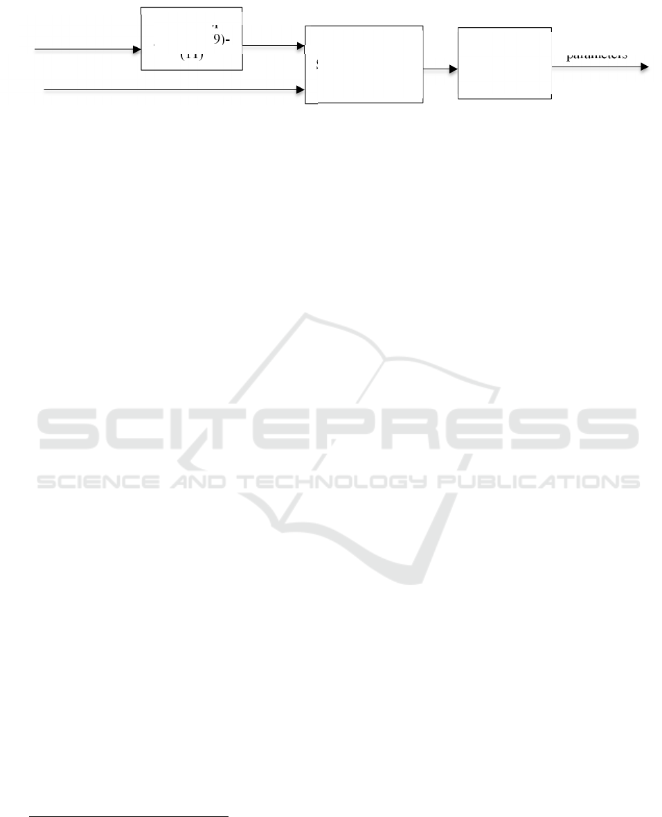
Figure 1: Overall block diagram of the proposed algorithm.
systems increases the perception capability of the
overall calibration system. To calibrate industrial
robots 3D positioning using neural networks, a Leica
SMART310 laser tracker is already used to calibrate
a PA10 robot arm (Aoyagi, Kohama, Nakata,
Hayano, & Suzuki, 2010). Leica AT960 and Leica
AT960-MR are used for neural networks position
calibration purpose of IRB1410 and a collaborative
industrial robot, respectively (Bai et al., 2021; Duong,
Trang, & Pham, 2021). A similar approach is used in
(Aoyagi et al., 2010; Nguyen et al., 2015) for
calibration purpose of Hyundai HH800 robot, a heavy
duty industrial robot, using a laser tracker system. To
avoid black box robot FK calibration, this paper
performs level II calibration of industrial robots by
tuning the parameters of its geometrical FK.
Therefore, the calibrated industrial robot FK is a
traceable one.
To perform level II calibration, this paper
proposes the use of multi-output least squares support
vector regressions (MLS-SVR), an advanced
regression model, to tune industrial robots FKs. This
algorithm is a variant of LS-SVR which is a powerful
regression algorithm originally introduced by
(Vapnik, 1999; Vladimir & Vapnik, 1998). LS-SVR
replaces convex quadratic programming problem
with convex linear system solving problem. Although
the original version of LS-SVR is meant for single
output case, its multi-output case has been developed
by (Xu, An, Qiao, Zhu, & Li, 2013). Using multi-
output LS-SVR (MLS-SVR), it is not required to treat
every single output individually. The superior
estimation power of MLS-SVR over partial least
squares (Abdi, 2003) and kernel partial least squares
regression (Rosipal & Trejo, 2001) for benchmark
regression problems has already been shown by
examples (Xu et al., 2013). Inspired by successful use
of MLS-SVR in literature, it is the preferred
algorithm in this paper to calibrate industrial robot
FK.
1
https://www.hexagonmi.com/-/media/Hexagon%20MI%
20Legacy/m1/metrology/general/brochures/Leica%20A
T960%20brochure_en.ashx (visited: 1/5/2022)
In this paper, an MLS-SVR is used to calibrate an
industrial robot’s FK model. Using a highly accurate
laser tracking system, Leica AT960, the absolute 3D
positions of an industrial robot are measured. The
measurement error of the laser tracking system which
is used in this paper is 3/
1
. This equipment is a
non-contact metrology one to accurately measure 3D
positions. The absolute positions from the laser
tracker are then used to estimate industrial robot FK
parameters. To do so, first industrial robot FK is
formulated as a regression problem. The parameters
of industrial robot FK are then estimated using MLS-
SVR which is a batch estimation approach. It is
observed that using the proposed calibration
approach, it is possible to decrease positioning error
in terms of mean absolute error (MAE) from its
measured value of 71.9 to 20.9. In other
words, using the proposed approach, MAE in all three
dimensions decreases by 71%.
This paper is organized as follows: in Section 2,
the overall methodology including an industrial robot
FK, and the proposed calibration approach are
introduced. The experiment setup to perform the
measurements is presented in Section 3. Experimental
results are presented in Section 4. Section 5 concludes
the paper. Acknowledgements and references for this
paper are presented in Section 6 and Section 7,
respectively.
2 METHODOLOGY
The overall calibration algorithm is presented in this
section. Robot joint angle encoders are generally used
in industrial robots for positioning purposes.
However, uncertainties in robot FK parameters and
geometrical uncertainties impose error on the
positional accuracies. To increase the accuracies of
FK parameters, MLS-SVR method is used in this
paper. Figure 1 demonstrates the overall block
diagram of the proposed approach. It is required to
Calibrate
d
forward
kinematic
parameters
Synchronisation
Regressor
generator (9)-
(11)
Robot join
t
angles
regressors
Absolute positions
measured by laser tracker
MLS-SVR
estimation
method
ICINCO 2022 - 19th International Conference on Informatics in Control, Automation and Robotics
264
formulate industrial robot FK in terms of a regression
problem. Synchronisation is required as joint angle
measurements and absolute position measurements
are conducted using two independent equipment.
Joint angle data gathered from industrial robot are at
higher frequency of 125Hz. Hence, they are
resampled at the laser tracker frequency to obtain
synchronisation between the robot and laser tracker.
No resampling is conducted on the measurements
gathered from laser tracker system to maintain its
high accuracy. The data samples occurring at linear
robot speed less than 2mm/s are used for static and
near static measurement and calibration. MLS-SVR
algorithm is then applied to industrial robot FK using
the resulting synchronised data. Details of the overall
process are explained in the coming subsections 2.1
and 2.2.
2.1 FK Model of UR5
Industrial robot FK is a function which expresses the
Cartesian coordinates of robot within 3D space as a
function of robot joint angles. Inverse kinematic is the
reverse procedure to assign appropriate joint angles to
industrial robots to maintain the desired positions and
orientations. The link transformation matrix from the
link -1 to the link using the Denavit–Hartenberg
(D-H) parameters of the robot as in Table 1 depends
on the corresponding joint angle of the industrial
robot and its D-H parameters (Kufieta, 2014; Sun,
Cao, Li, Liang, & Huang, 2017).
=
−
−
0
00 01
(1)
Table 1: The DH parameters of the 6DOF robot.
Lin
k
1
0
/
2
2
0
0
3
0
0
4
0
/2
5
0
−/2
6
0 0
where
′,=1,…,6 represent the joint angle ,
′,=1,…,6,
′,=1,…,6, and
,=1,…,6
present other DH parameters of robot. Furthermore,
,
,
,and
,=1,...6 represent (
),
2
https://www.universal-robots.com/articles/ur/application
-installation/dh-parameters-for-calculations-of-kinematic
s-and-dynamics/ (visited: 1/5/2022)
(
),
, and (
),=1,...,6 ,
respectively. Overall robot transformation matrix in
robot base coordinates is obtained as follows.
=
=
(2)
The end effector coordinates in all three dimensions
are obtained as follows.
=
+
+
+
−
+
+
+
−
−
+
+
+
(3)
=
−
−
+
−
+
+
+
−
−
+
+
+
(4)
=
+
+
+
−
−
+
+
+
−
−
−
+
(5)
Although the values of FK parameters are unknown
and will be estimated in this paper, their numerical
values according to the robot manufacturer are as
follows
2
.
=0.08916,
=−0.425,
=−0.392,
=0.1092,
(6)
=0.0947,
=0.0823+
(7)
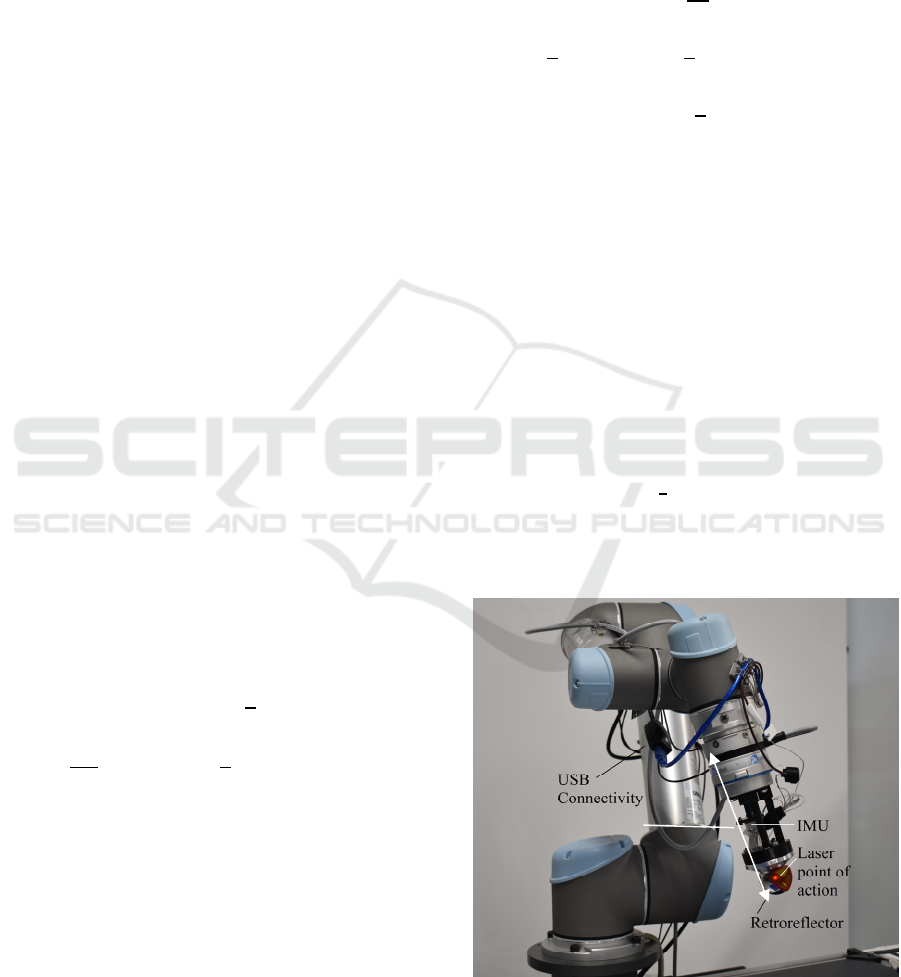
where is the distance between the centre of the
retroreflector and the centre of the robot end-effector
(see Figure 2) which is approximately equal to
0.1695. Furthermore,
=
=0, and
=0,=1,4,5,6.
(8)
To conduct the calibration, the direction of the robot
is considered on its downward orientation with its
TCP axis-rotation vector equal to
(
00
)
.
From (3)-(5), the regressor vectors corresponding to
three dimensions: x, y, and z are formulated for MLS-
SVR to estimate robot FK parameters.
=
,
,
,
,
,
,
,
,
,
,
,
,
,1
,
(9)
Improving the Positional Accuracy of Industrial Robots by Forward Kinematic Calibration using Laser Tracker System
265
=
,
,
,
,
,
,
,
,
,
,
,
,
,1
(10)
and
=
,
,
,
,
,
,
,
,
,
,1
(11)
These regressor values are used in the next subsection
to tune the FK parameters
2.2 Multi-output Least Squares
Support Vector Regression
Let the multioutput regression problem to be solved
be:
Υ
=Φ
Π
(12)
where Υ=
∈ℝ
×
, and ,,and are
the position measurements in all three dimensions
using the laser tracker system. The regressor matrix
Φ is defined as follows.
Φ=
⋮
(13)
where Φ∈ℝ
×
is the regressor matrix and Π=
Π
Π
Π
∈ℝ
×
is the vector of unknown
parameters of industrial robot FK in laser tracker
coordinates.
,
, and
represent the i-th
regressor vector sample. Xu et al. recently proposed
MLS-SVR for solving the multioutput regression
problems. The objective function to be minimized in
this case is as follows (Xu et al., 2013).
min
∈ℝ
,∈ℝ
×
ℐ
(
,,Ξ
)
=
1
2
trace
+
2
trace
(
V
V
)
+
2
(
Ξ
Ξ
)
,
..
Υ
=Φ
+Ξ
(14)
where the matrix Ξ=
ξ
ξ
ξ
∈ℝ
×
is a
matrix consisting of slack variables, Π=
(
+
,
+
,
+
)
∈ℝ
×
and ∈ℝ
is a
positive real regularized parameter. The Lagrangian
function to solve the problem of (13) is
ℒ
(
,,Ξ,A
)
=
ℐ
(
,,Ξ
)
−
(
(
Φ
)
+Ξ−
Υ
)
(15)
where =
(
,
,
)
∈ℝ
×
, include all
Lagrange multipliers,
∈ℝ
×
,=1,2,3. Using
the Karush-Kuhn-Tucker conditions for optimality
and a set of algebraic modifications leads to an
equivalent optimisation problem which does not
include
parameters.
min
∈ℝ
×
ℐ
(
,Ξ
)
=
54
1
1
V
+
6
(
V
V
)
+
2
(
Ξ
Ξ
)
,
..
Υ
=Φ
+
3
Φ
1
,1,3+Ξ
(16)
where 1
=
111
. The solution to the
optimisation problem of (16) is available using the
method presented in (Xu et al., 2013). The method to
solve the optimisation problem of (16) is summarised
in the following six main steps.
1. solve , and from =, and =Υ
where =(1
,1
,...,1
)∈
ℝ
×
, and =Ω+
+(3/)∈
ℝ
×
,=(,,)∈ℝ
×
,
=Φ
Φ∈ℝ
×
2. Compute =
3. Find and as =
Υ, =−
4. Find from =
ΦA
5. Find
from
=
∑
Φ
6. Find Π from =
(
+
,
+
,
+
)
Figure 2: UR5 with retroreflector mounted on it as the target
for laser tracker.
d
ICINCO 2022 - 19th International Conference on Informatics in Control, Automation and Robotics
266

Figure 3: Overall calibration system: UR5 industrial robot
and Leica laser tracker system.
3 EXPERIMENT SETUP
3.1 Hardware Setup
The hardware used to perform this experiment is
composed of an industrial robot and a calibration
equipment (see Figure 3). In this subsection, detailed
explanations of the equipment are presented.
3.1.1 Calibration Equipment
To conduct the calibration test, the 3D real time
position of a retroreflector mounted on the UR5 end
effector is measured using a laser tracker. The laser
tracker used in this experiment is AT960-MR from
Hexagon metrology GMBH, Wetzlar. It is a widely
used measurement device in industry to inspect
critical distances, locations and surfaces (Kyle, 1999)
(see Figure 4). The target used in these experiments is
a precision Leica 1.5” red ring reflector which is
detectable through the laser tracker at the maximum
distance of 60 m @10Hz with the accuracy of
3/. The reflector used in this experiment is using
the principle of corner cube. To reflect the beam, three
plane mirrors at right angles to one another are used.
The measurement point is the centre of the reflector.
Further specifications and environmental conditions
of the laser tracker are presented in Table 2.
3.1.2 Industrial Robot
The industrial robot used in these experiments is a
Universal Robots, UR5 capable of handling 5Kg load
with angular velocity of 180°/. Real time
industrial robot joint angles are measured using on-
3
https://github.com/UniversalRobots/Universal_Robots_
ROS_Driver
board joint angle encoders. To collect this data, wired
network connectivity is used to connect the main robot
controller to a PC. The software used for connectivity
is ROS Melodic operating under Linux 18.04
operating system. The ROS driver used for UR5 is the
one available through a GitHub webpage
3
. This ROS
driver publishes some rostopics which contain joint
angle data including joint angle values, angular
velocities, and motor currents. The sample time for the
data transfer from robot to PC slightly varies but its
mean value is equal to 8. Overall, 38 waypoints
are programmed for the robot, and it travels them
linearly in 600 sec. It is required to resample position
data from the robot to match laser tracker frequency
(10Hz).
3.1.3 Data Gathering and Pre-processing
To gather data points to perform static calibration, as
it is required for a level II robot calibration, the
absolute position data are gathered from the robot
using the laser tracker system. The laser tracker is
connected to the PC using a Wi-Fi connectivity. The
software used for data gathering is Spatial Analyzer
software (see Figure 5), and the sample time for this
device is set to 100 msec. For measurements in Spatial
Analyzer software, it is required to assign the three
axes and the origin. To do so, two linear motions are
performed using the robot along x-axis and y-axis.
The zero coordinate for the laser tracker and its three
axes are assigned within Spatial Analyzer software.
The total number of points gathered using the laser
tracker is equal to 6000. Moreover, since robot and
laser tracker use different timing, it is required to
synchronise them i.e., to shift them so that they match
each other timewise. Finally, for performing static and
near static calibration, the points at which the linear
speed of the robot are less than 2mm/sec are extracted.
Total number of these points are 209 points.
4 EXPERIMENTAL RESULTS
4.1 Results
The results of the calibration process proposed in this
paper are presented in Figures 6- 8. These figures
show that the positions obtained through the
calibrated UR5 FK are much closer to its real 3D
positions measured by laser tracker. The numerical
values presented in Table 3 demonstrate the
Industrial
robot
Calibration
tool
Improving the Positional Accuracy of Industrial Robots by Forward Kinematic Calibration using Laser Tracker System
267
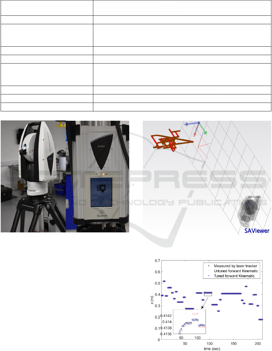
Table 2: Measuring equipment characteristics and specifications.
Environmental working conditions
IP54: The IEC-certified sealed unit guarantees ingress protection
against dust and other contaminants.
Operating temperature Wide operating temperature range of -15 to 45 degrees Celsius
Temperature compensation
MeteoStation: Integrated environmental unit monitors conditions
including temperature, pressure, and humidity to compensate for
changes
ISO certification ISO 17025
Connectivity Wifi and LAN
Detector features
Red ring reflector - 1.5” radius: 19.05 mm ±0.0025 mm, centring of
optics: < ±0.003 mm, ball roundness: ≤0.003 mm, acceptance angle:
±30°, weight:170gr
Data output rate Measurement rate of up to 1000 points per second
Distance accuracy 40 metres in diameter and a 6DoF measuring volume of up to 20 metres
Laser safety Laser class 2
Figure 4: Laser tracker system (a) Camera and tracking
system (b) Controller unit.
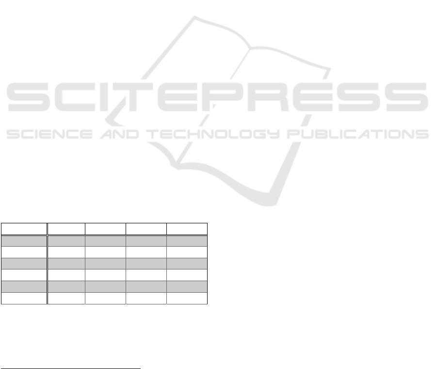
improvement made using the proposed calibration
method. In all three positional dimensions, the MAE
associated with the calibrated FK of UR5 is less than
its uncalibrated value. It is further observed that the
mean MAE of all three dimensions is reduced
from71.9 for uncalibrated FK to 20.9 for the
calibrated FK using the proposed calibration method,
which is 71% improvement in the measurement.
The trend of error associated with original FK of
industrial robots and its calibrated version are
presented in Figures 9- 11, respectively. It is observed
from these figures, that errors corresponding to the
calibrated FK are much less than the ones associated
with uncalibrated FK.
Figure 5: Points measured by laser tracker system in Spatial
Analyzer software.
Figure 6: Robot movements in 3D coordinates, x-axis.
ICINCO 2022 - 19th International Conference on Informatics in Control, Automation and Robotics
268
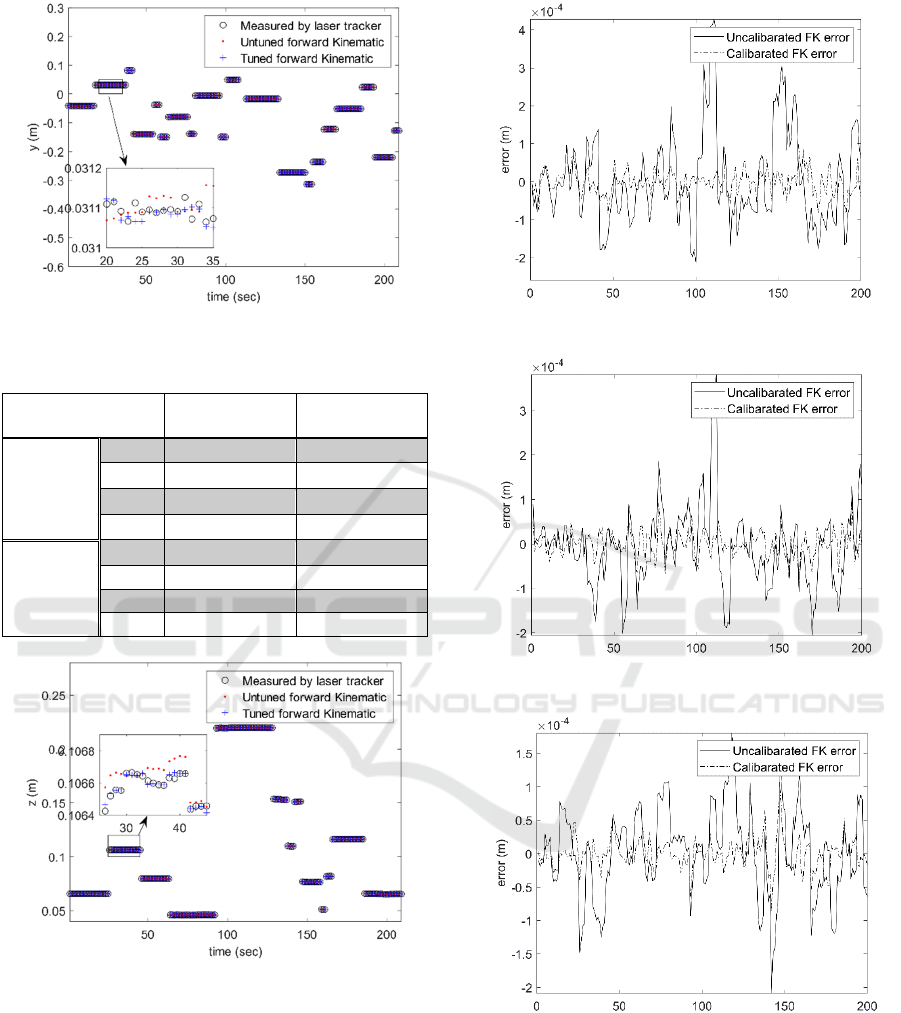
Figure 7: Robot movements in 3D coordinates, y-axis.
Table 3: FK error indexes.
Performance
indexes
Calibrate
d
Uncalibrate
d
MAE
X
24.4 94.6
Y
21.7 67.9
Z
16.5 53.3
Mean
20.9 71.9
X
32.0 124.2
Y
28.6 99.1
Z
23.7 67.6
Mean
28.3 99.8
Figure 8: Robot movements in 3D coordinates, z-axis.
5 CONCLUSIONS AND FUTURE
RESEARCH
The uncertainties associated with FK of industrial
robots are mainly due to manufacturing and assembly
tolerances, dimension measurement uncertainties,
and wears and tears of robot. FK uncertainties result
in positioning error. This paper presents an
FK calibration method for industrial robot using laser
Figure 9: Position error in x-axis.
Figure 10: Position error in y-axis.
Figure 11: Position error in z-axis.
tracker measurement system. Robot joint angles are
measured using on board joint encoders. Robot joint
angles are collected and transferred to PC using ROS-
Melodic software. Static and near static
measurements are performed on the robot. The
industrial robot FK is formulated as a multi-output
regression problem. The industrial robot coordinates
measured by a laser tracker system (Leica AT960) is
Improving the Positional Accuracy of Industrial Robots by Forward Kinematic Calibration using Laser Tracker System
269

then used in an MLS-SVR algorithm to calibrate FK.
The industrial robot used in the calibration
experiment is an UR5, an industrial robot
manufactured by Universal Robots. It is observed that
using the proposed calibration approach, it is possible
to decrease the position errors in terms of mean
absolute errors from its measured value of 71.9 to
20.9 which is 71% improvement.
As a future study, data fusion between data
gathered from inertia measurement unit and
gyroscopic measurements will be considered to
improve the accuracy of positional measurements.
ACKNOWLEDGEMENT
This work is funded and supported by the Engineering
and Physical Sciences Re-search Council (EPSRC)
under grant number: EP/T023805/1— High-accuracy
robotic system for precise object manipulation
(HARISOM). We gratefully acknowledge Prof.
Svetan Ratchev and Dr. Peter Kendall of University of
Nottingham for their helps towards Leica laser tracker
measurements.
REFERENCES
Abdi, H. (2003). Partial least square regression (PLS
regression). Encyclopedia for research methods for the
social sciences, 6(4), 792-795.
Aoyagi, S., Kohama, A., Nakata, Y., Hayano, Y., & Suzuki,
M. (2010). Improvement of robot accuracy by
calibrating kinematic model using a laser tracking
system-compensation of non-geometric errors using
neural networks and selection of optimal measuring
points using genetic algorithm. Paper presented at the
2010 IEEE/RSJ International conference on intelligent
robots and systems.
Bai, M., Zhang, M., Zhang, H., Li, M., Zhao, J., & Chen, Z.
(2021). Calibration Method Based on Models and
Least-Squares Support Vector Regression Enhancing
Robot Position Accuracy. IEEE Access, 9, 136060-
136070.
Duong, Q. K., Trang, T. T., & Pham, T. L. (2021). Robot
Control Using Alternative Trajectories Based on
Inverse Errors in the Workspace. Journal of Robotics,
2021.
Gao, G., Li, Y., Liu, F., & Han, S. (2021). Kinematic
calibration of industrial robots based on distance
information using a hybrid identification method.
Complexity, 2021.
Khanesar, M. A., & Branson, D. (2022). Robust Sliding
Mode Fuzzy Control of Industrial Robots Using an
Extended Kalman Filter Inverse Kinematic Solver.
Energies, 15(5), 1876.
Kufieta, K. (2014). Force estimation in robotic
manipulators: Modeling, simulation and experiments.
Department of Engineering Cybernetics NTNU
Norwegian University of Science and Technology.
Kyle, S. (1999). Operational features of the Leica laser
tracker.
Nguyen, H.-N., Zhou, J., & Kang, H.-J. (2015). A
calibration method for enhancing robot accuracy
through integration of an extended Kalman filter
algorithm and an artificial neural network.
Neurocomputing, 151, 996-1005.
Rosipal, R., & Trejo, L. J. (2001). Kernel partial least
squares regression in reproducing kernel hilbert space.
Journal of machine learning research, 2(Dec), 97-123.
Roth, Z., Mooring, B., & Ravani, B. (1987). An overview
of robot calibration. IEEE Journal on Robotics and
Automation, 3(5), 377-385.
Sun, J.-D., Cao, G.-Z., Li, W.-B., Liang, Y.-X., & Huang,
S.-D. (2017). Analytical inverse kinematic solution
using the DH method for a 6-DOF robot. Paper
presented at the 2017 14th international conference on
ubiquitous robots and ambient intelligence (URAI).
Vapnik, V. (1999). The nature of statistical learning theory:
Springer science & business media.
Vladimir, N. V., & Vapnik, V. (1998). Statistical learning
theory. Xu JH and Zhang XG. translation. Beijing:
Publishing House of Electronics Industry, 2O04.
Xu, S., An, X., Qiao, X., Zhu, L., & Li, L. (2013). Multi-
output least-squares support vector regression
machines. Pattern Recognition Letters, 34(9), 1078-
1084.
ICINCO 2022 - 19th International Conference on Informatics in Control, Automation and Robotics
270
