
A Novel Constrained Trajectory Planner for Safe Human-robot
Collaboration
Matteo Melchiorre
a
, Leonardo Sabatino Scimmi
b
, Stefano Mauro
c
and Stefano Pastorelli
d
Department of Mechanical and Aerospace Engineering, Politecnico di Torino, C.so Duca degli Abruzzi 24, Turin, Italy
Keywords: Collaborative Robotics, Collision Avoidance, Real-time, Motion Planning.
Abstract: This paper presents a novel collision avoidance algorithm for collaborative robotics that can influence the
collision-free trajectory of the robot according to preferred directions with respect to the human posture. The
aim is to avoid the human body parts in a controlled manner so that the robot trajectory is predictable. The
algorithm is based on closed loop inverse kinematics and uses velocity commands to modify the robot
trajectory in real-time. The existing human tracking devices allow to measure the human posture in three
dimensions. The idea is to combine the human posture estimation with repulsive volumes, i.e. regions that
approximate the human size and that produce repulsive velocities on the robot, and to add attractive surfaces
made of cylindrical sectors to condition the avoidance manoeuvre in a chosen direction. The algorithm is
tested in a simulation environment built with the model of a collaborative robot and a mock-up of the human,
whose motion is generated from real data acquired by 3d vision sensors. The results show the effectiveness
of the proposed method during a pick and place task in common scenarios, where the human intersects the
robot planned path with different body parts.
1 INTRODUCTION
Human-robot collaboration (HRC) happens when
human and robot operate within the same workspace
to accomplish a task. The industrial application of
HRC is expressed as collaborative robotics. The
documents (Krüger, Lien, & Verl, 2009; Vicentini,
2021) give an overview of the most relevant findings
and applications. One of the main branches of study
concerns the possibility to drive the robot with
collision-free trajectories that satisfy task and safety
constraints. In particular, responsive collaboration
requires the robot to react in real time to human
motion, when they both move in the same
environment [3].
Adjusting robot trajectory on the go is something
that can be dealt with online collision avoidance
techniques. Two different approaches can be
distinguished. Some studies consider slowing down
or stopping the robot when the human is detected in a
short range (Byner, Matthias, & Ding, 2019; Corrales,
Candelas, & Torres, 2011; Pellegrinelli, Moro,
a
https://orcid.org/0000-0002-4409-186X
b
https://orcid.org/0000-0002-0537-2984
c
https://orcid.org/0000-0001-8395-8297
d
https://orcid.org/0000-0001-7808-8776
Pedrocchi, Molinari Tosatti, & Tolio, 2016).
However, this reduces task efficiency (Scimmi,
Melchiorre, Troise, Mauro, & Pastorelli, 2021). Other
works propose to deviate the robot path to achieve a
continuous collision-free motion (Chen & Song,
2018; Flacco, Kroger, Luca, & Khatib, 2012;
Kaldestad, Haddadin, Belder, Hovland, & Anisi,
2014; Liu & Tomizuka, 2016; Mauro, Scimmi, &
Pastorelli, 2017; Melchiorre, Scimmi, Pastorelli, &
Mauro, 2019; Merckaert et al., 2022; Parigi Polverini,
Zanchettin, & Rocco, 2017; Ragaglia, Zanchettin, &
Rocco, 2018; Safeea, Neto, & Bearee, 2019; Schmidt
& Wang, 2014; Zanchettin, Rocco, Chiappa, & Rossi,
2019). In the latter, the well-known artificial potential
field (APF)-based techniques are the most common
(Chen & Song, 2018; Flacco et al., 2012; Kaldestad
et al., 2014; Merckaert et al., 2022; Parigi Polverini et
al., 2017; Safeea et al., 2019; Schmidt & Wang,
2014). The idea is that the robot navigates attracted
by the target, while repulsive effects act nearby the
obstacles. Depending on the control law, some
algorithms stand on command vector calculated from
Melchiorre, M., Scimmi, L., Mauro, S. and Pastorelli, S.
A Novel Constrained Trajectory Planner for Safe Human-robot Collaboration.
DOI: 10.5220/0011352200003271
In Proceedings of the 19th International Conference on Informatics in Control, Automation and Robotics (ICINCO 2022), pages 539-548
ISBN: 978-989-758-585-2; ISSN: 2184-2809
Copyright
c
2022 by SCITEPRESS – Science and Technology Publications, Lda. All rights reserved
539
the gradient of the potential field, other variants
compute repulsive velocity components to be added
to the velocity vector related to the target. The main
advantages of APF-based techniques are: i) easy
implementation; ii) fast computation, as the trajectory
is affected locally and does not require to be globally
redefined. On the other hand, the drawback of local
techniques is that the alternative trajectories are less
controllable, since dynamic environments means
absent or limited a-priori information on obstacle
motion, thus repulsive effect can occur anytime and
across any direction during robot motion.
Regarding the execution of the collision-free
trajectory, the standards (“ISO/TS 15066. Robots and
Robotic Devices: Collaborative Robots,” 2016) do
not provide any requirements. However, controlling
robot evasive motion according to human preferences
can be fundamental. For instance, robot movement
predictability affects the psychophysical response of
the human (Dragan, Bauman, Forlizzi, & Srinivasa,
2015; Koppenborg, Nickel, Naber, Lungfiel, &
Huelke, 2017). The robot motion is predictable if it
matches what the human would expect, given the
robot task (Dragan et al., 2015). If the robot moves
undisturbed, the human can anticipate robot intention
due to task repeatability. On the other hand, when the
operator is within robot range of motion and collision
avoidance activates, the human body represent a
dynamic obstacle. In the last case, if the collision
avoidance manoeuvre is not controlled in some way,
predicting the robot collision-free path can be
difficult for the operator.
This work proposes an improved collision
avoidance algorithm based on repulsive and attractive
velocities that conditions the robot collision-free path
in a controlled manner. The originality of the
proposed algorithm consists in: i) addressing the
alternative path problem in the context of
collaborative robotics; ii) combining repulsive and
attractive effects around obstacles in a novel form,
with a view to evasive and controlled robot motion.
2 HUMAN-ORIENTED
COLLISION AVOIDANCE
2.1 Problem Overview
In the context of collision avoidance, representing
robot and obstacles real shapes with simple
geometries can be convenient for different reasons. In
collaborative robotics applications, for example, it is
common to approximate the human and robot sizes
with cuboids, ellipsoids and cylinders (Byner et al.,
2019; Chen & Song, 2018; Corrales et al., 2011;
Flacco et al., 2012; Liu & Tomizuka, 2016; Martinez-
Salvador, Perez-Francisco, & Del Pobil, 2003;
Merckaert et al., 2022; Parigi Polverini et al., 2017;
Pellegrinelli et al., 2016; Safeea et al., 2019). This
allows to consider a safety margin varying geometry
sizes and simplifies distance calculation.
Concerning collaborative robots, they are usually
6dof manipulators. Reconstructing the pose is
straightforward as this can be calculated from
feedback signals through direct kinematics. For
instance, spheres can be placed along the kinematic
chain to enclose the robot body.
As regard the human, due to intrusiveness of
wearable sensors, many studies use 3D cameras
equipped with human tracking software (Chen &
Song, 2018; Flacco et al., 2012; Kaldestad et al.,
2014; Melchiorre, Scimmi, Mauro, & Pastorelli,
2021; Parigi Polverini et al., 2017; Pellegrinelli et al.,
2016; Ragaglia et al., 2018; Safeea et al., 2019;
Schmidt & Wang, 2014; Scimmi et al., 2021;
Zanchettin et al., 2019). The output is given in terms
of human body joint positions, commonly referred as
skeleton. This comes in handy when building the
human envelope, as geometry elements can be placed
on the skeleton.
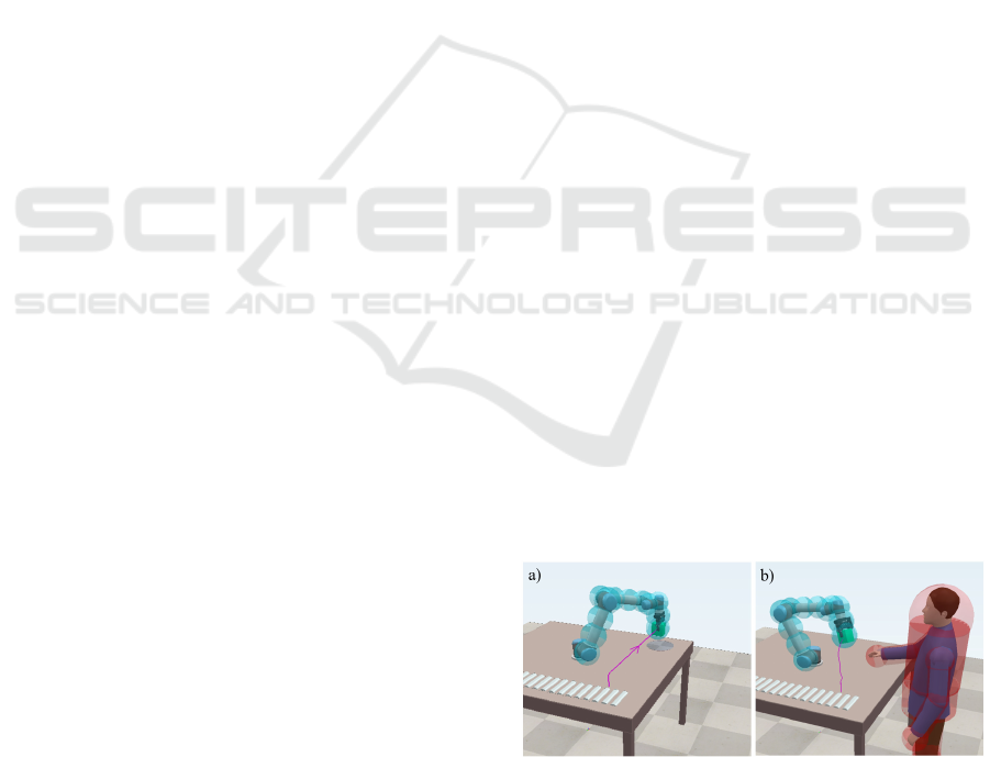
In Figure 1 an example is shown. A 6dof
collaborative robot is represented with n spheres
centred in control points, opportunely displaced along
the kinematic chain. The human shape is obtained as
an augmented skeleton, made of spheres and
cylinders. Suppose that the robot task consists in
reaching a target position. If the human intersects the
planned path, e.g. with his hand as in a collaborative
assembly (Scimmi et al., 2021), regardless of the
robot path as long as it maintains a protective
distance, the task carries on safely. This can be dealt
with existing real-time collision avoidance
techniques.
However, if the operator can infer a-priori where
the robot would pass, the robot motion becomes
predictable. For this purpose, the robot trajectory can
be constrained, e.g. in front of the hand, so that the
human is aware of the alternative path.
Figure 1: a) Robot planned task. b) Example of Human-
robot collision avoidance.
ICINCO 2022 - 19th International Conference on Informatics in Control, Automation and Robotics
540
2.2 Attractive and Repulsive
Geometries
In the following, with the expression repulsive
geometry is intended a space region that provides a
repulsive effect on the robot. Similarly, the
expression attractive geometry indicates a region the
robot is attracted by.
The role of attractive geometries is to condition
the robot path during obstacle avoidance. Consider
the example of Figure 1. In combination with the
repulsive sphere on the human hand, one can add a
cylindrical surface that acts by attracting the robot on
a chosen side, as in Figure 2. In this way, the robot
would cross the hand on the front side. This is not
obvious since by using only the repulsive sphere, the
robot can pass either above or below the human hand.
With a similar approach, one can use patches attached
to any part of the skeleton, e.g., the forearm, to
prepare attractive regions at will.
Attractive geometries fixed to the skeleton move
according to human motion. Thus, preferred collision
avoidance directions are defined relatively to the pose
of the body parts. Attractive geometries moving with
body parts can be thought for a close collaboration, as
the attraction depends on position and orientation of
skeleton segments.
Figure 2: Attractive surfaces and repulsive volumes.
2.2.1 Formulation
The formula for repulsive velocities has been
introduced in (Flacco et al., 2012). Attractive
geometries are introduced in a similar manner, with a
formulation that provide a smooth attractive vector
field.
As the original usage of attractive regions is one
of the main contributions of this work, the related
formula is discussed more in depth. After, a summary
is also given for repulsive geometries.
Attractive Geometries. In this work, attractive
geometries are built from cylindrical primitives.
The role of attractive geometries is to apply an
attractive effect in terms of velocity to the end
effector of the robot. To orient the attraction, it is
convenient using cylindrical sectors, as introduced in
Figure 2.
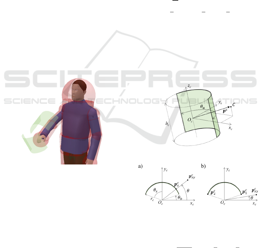
A generic sector of a cylinder is shown in Figure
3. The cylinder is centred in the frame 𝑂
−𝑥
𝑦
𝑧
,
with the 𝑧
axis aligned with the cylinder axis. The
angle 𝜃
identifies the attractive arc of cylinder.
Given 𝜃
and assuming that the attractive region is
symmetric with respect to 𝑦
, the angles 𝜃
and 𝜃
are introduced as:
𝜃
=
𝜃
2
,0<𝜃
≤𝜋
(1
)
𝜃
=
𝜋
2
−𝜃
,−
𝜋
2
≤𝜃
<
𝜋
2
(2
)
Let 𝒑
=𝑝
𝑝
𝑝
denote the generic point C
observed in the cylinder frame. The attractive range
is limited within the height of the cylinder ℎ
, so that
the attractive velocity acts only for
|
𝑝
|
≤ℎ
/2. In
this case, the intensity of the attraction in 𝒑
is
modelled as a function of the distance from the
cylinder. As the distance does not depend on 𝑝
, the
formula is obtained observing the 𝑥
𝑦
plane.
Figure 3: Attractive cylindrical sector.
Figure 4: Analysis of the attractive arc.
Let 𝒑
=𝑝
𝑝
0
be the projection of the
point on the 𝑥
𝑦
plane. The angle 𝜃 is introduced as:
𝜃=sin
𝑝
𝒑
, −
𝜋
2
≤𝜃≤
𝜋
2
(3
)
A Novel Constrained Trajectory Planner for Safe Human-robot Collaboration
541
The distance 𝑑
from the attractive source
depends on 𝜃. Two cases can be distinguished.
Case 1: 𝜃
≤𝜃≤
The distance is calculated considering the closest
point on the surface of the cylinder 𝒑
(see Figure
4a). The displacement 𝒅
is defined as:
𝒅
=𝒑
−𝒑
(4)
Let 𝑟
be the cylinder radius, 𝒑
can be written as:
𝒑
=𝑟
𝑝
𝒑
𝑟
𝑝
𝒑
0
(5)
Case 2: −
≤𝜃<𝜃
Depending on the sign of 𝑝
, the distance is
computed considering the two ends of the arc,
denoted as 𝒑
and 𝒑
(see Figure 4b).
If 𝑝
≥0:
𝒅
=𝒑
−𝒑
(6)
where 𝒑
can be written as:
𝒑
=
𝑟
cos𝜃
𝑟
sin𝜃
0
(7)
If 𝑝
<0:
𝒅
=𝒑
−𝒑
(8)
with 𝒑
calculated as:
𝒑
=
−𝑟
cos𝜃
𝑟
sin𝜃
0
(9)
The attractive velocity 𝒗
acting at the point 𝒑
is:
𝒗
=𝑣
𝒅
‖
𝒅
‖
(10
)
where 𝑣
is the magnitude of the attractive velocity,
defined as:
𝑣
=
𝑣
,
1+𝑒
(11
)
In (11), 𝑣
,
indicates the maximum value of the
attractive velocity, while 𝛼
and 𝜌
are the
parameters that regulates the variability of 𝑣
according to 𝑑
=
‖
𝒅
‖
.
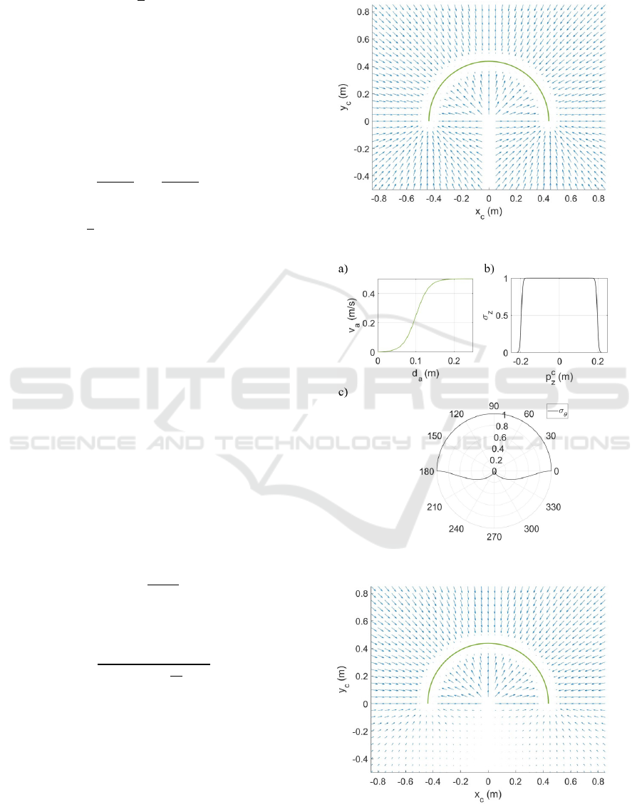
An example of an attractive velocity vector field
resulting from (10) is shown in Figure 5. A
semicylinder is considered, thus 𝜃
=𝜋. The
magnitude 𝑣
has been modelled as in (11), with
𝑣
,
=0.5 𝑚/𝑠, 𝜌
=0.2 𝑚 and 𝛼
=6 (see
Figure 6a).
Figure 5: Attractive velocity vector field.
Figure 6: Parameters of the attractive function.
Figure 7: Modified attractive velocity vector field.
ICINCO 2022 - 19th International Conference on Informatics in Control, Automation and Robotics
542
By observing Figure 5, the points 𝑝
=0
encounter a discontinuity for 𝑝
≤0, i.e. for 𝜃=
−
. Another discontinuity, that is not visible in the
two-dimensional representation of Figure 5 but that
still exist, is the one at the boundaries when 𝑝
=
−ℎ
/2 or 𝑝
=ℎ
/2.
A smoother transition at the boundaries can be
obtained by introducing the coefficients 0≤𝜎
≤1
and 0≤𝜎
≤1, so that the attractive velocity in (10)
becomes:
𝒗
=𝜎
𝜎
𝑣
𝒅
‖
𝒅
‖
(12
)
𝜎
=
⎩
⎪
⎪
⎨
⎪
⎪
⎧
1
1 + 𝑒
, −
ℎ
2
≤𝑝
≤0
1
1+𝑒
, 0<𝑝
≤
ℎ
2
(13
)
𝜎
=𝑟𝑒𝑎𝑙
1−
sin
(
𝜃+𝜋
)
(14
)
In (13), 𝛼
and 𝜌
are the parameters that define the
shape of 𝜎
. The functions 𝜎
(𝑝
𝑧
𝑐
) and 𝜎
(
𝜃
)
are
plotted in Figure 6b and 6c.
The cardioid function (14) is suited for the
application because of the properties of being null for
𝜃=−
and of assuming the value 1 for 0≤𝜃≤
.
This is reasonable since the role of the cylindrical
sector is to attract the robot on one side of the
obstacle. The velocity vector field scaled by the factor
𝜎
is represented in Figure 7.
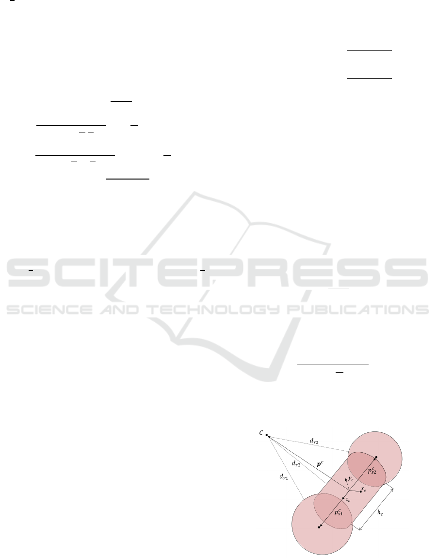
Repulsive Geometries. The human can be seen as a
kinematic chain, where the body parts like chest,
arms, forearms are connected by joints, such as
shoulders and elbows. The size of the body parts
which are provided with relative motion can be
approximated by capsules, i.e. cylinders rounded with
spherical cups at the ends. as in (Liu & Tomizuka,
2016; Safeea et al., 2019). In this work the radius of
the cups can also be greater than the cylinder radius.
The only constraint is that sphere centers lie on the
axis of the cylinder.
The repulsive vector field related to each capsule
is computed as a function of the distance from the
geometry. The difference with attractive cylindrical
sectors is that repulsive regions are intended as
volumes that robot cannot access. Thus, repulsive
vector fields are defined only outside of this region.
On the other hand, the attractive geometry can be seen
as an attractive wall, that can be an open surface.
To calculate the distance between a generic point
and a capsule, it is convenient observing the point in
the frame 𝑂
−𝑥
𝑦
𝑧
, with 𝑧
aligned with the axis
of the cylinder and 𝑂
placed at the middle. Let 𝒑
and 𝒑
denote the centers of the spheres of radii 𝑟
and 𝑟
respectively, the displacements between 𝒑
and its projections on the spherical cups are:
𝒅
=
(
𝒑
−𝒑
)
−𝑟
𝒑
−𝒑
‖
𝒑
−𝒑
‖
(15)
𝒅
=
(
𝒑
−𝒑
)
−𝑟
𝒑
−𝒑
‖
𝒑
−𝒑
‖
(16)
For the lateral surface of the cylinder, the
displacement is defined like (4), but with opposite
direction:
𝒅
=𝒑
−𝒑
(17)
The repulsive distance
𝑑
from the capsule is
obtained as:
𝑑
=
min
(
𝑑
,𝑑
,𝑑
)
,
|
𝑝
|
≤ℎ
/2
min
(
𝑑
,𝑑
)
, 𝑝
>ℎ
/2
min
(
𝑑
,𝑑
)
, 𝑝
<ℎ
/2
(18)
Thus, the repulsive velocity 𝒗
acting at the point 𝒑
is obtained as:
𝒗
=𝑣
𝒅
‖
𝒅
‖
(19)
where 𝒅
is (15), (16) or (17), depending on the
minimum value resulting from (18). The magnitude
of the repulsive velocity 𝑣
, defined as:
𝑣
=
𝑣
,
1+𝑒
(20)
In (18), the parameters 𝑣
,
, 𝛼
and 𝜌
have the
same meaning of the ones introduced in (11).
Figure 8: Point-capsule distance calculation.
A Novel Constrained Trajectory Planner for Safe Human-robot Collaboration
543
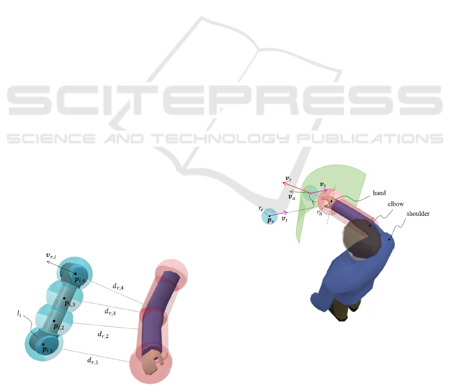
2.3 Collision Avoidance Strategy
As introduced in Section 2.2, the idea is that the robot
navigates in a vector field which is the sum of
repulsive and attractive sources opportunely placed
on the human shape.
The repulsive action can be dealt with the
multiple collision avoidance algorithm presented in
(Scimmi, Melchiorre, Mauro, & Pastorelli, 2018)that
consider repulsive velocities on each link of the robot
depending on human-robot distances.
To simplify distance calculation, the size of the
generic link 𝑙
of the robot is approximated with a
number 𝑛
of spheres centred in 𝒑
,
, with 𝑗=
1,2…𝑛
, as shown in Figure 9. With a similar
approach, human body parts can be represented by
capsules.
For each point 𝒑
,
, the distance from each
repulsive source can be evaluated with (18). Let 𝒅
,
be the distance between the control point 𝒑
,
and the
closest repulsive source. Thus, the minimum distance
between the robot link and the human is obtained as:
𝑑
,
=min𝑑
𝑟,1
,𝑑
𝑟,2
,…,𝑑
𝑟,𝑛
𝑖
−𝑟
𝑖
(21)
where 𝑟
is the radius of the sphere of the robot link.
The repulsive velocity (19) is applied to the control
point related to
𝑑
,
(e.g. point 𝒑
,
in Figure 9).
Commands to the robot are given in terms of joint
velocities
𝒒
:
𝒒
=
𝐽
𝑃,𝑖
𝑇
(𝒒
)𝒗
𝑟,𝑖
(22)
where 𝒗
,
is the repulsive velocity related to 𝑙
, 𝒒
is
the vector of joint positions that affect the motion of
𝑙
and 𝐽
,
is the partial Jacobian related to the control
point the repulsive action is applied on. Notice that
𝐽
,
is a three-row matrix that affects the end-effector
linear velocity only (Siciliano, Sciavicco, Villani, &
Oriolo, 2009).
Figure 9: Robot link-capsule distances.
Concerning the attraction, it is limited to the end-
effector. To describe how to combine attraction with
repulsion, the example of the human hand is
considered. However, the same strategy can be
applied for any repulsive source.
Assume that one wants to influence the robot end-
effector 𝒑
so that it chooses passing in front of the
hand during collision avoidance. An attractive source
as in Figure 3 can be centred on the hand. The
direction of the attractive cylinder 𝑦
axis is identified
considering the segment connecting the elbow to the
hand. Besides, the 𝑧
axis of the attractive cylinder is
chosen perpendicular to the plane defined by hand,
elbow and shoulder.
Let 𝑟
be the radius of the robot sphere centred in
the control point 𝒑
. The strategy consists of
activating both attraction and repulsion effects after
that 𝒑
crosses the attractive surface. A possible
solution is to set 𝒗
=0 outside of 𝑟
and to choose
the radius and the height of the attractive cylinder as:
𝑟
=𝑟
+𝑟
+𝜌
(23)
ℎ
=2𝑟
(24)
where 𝑟
identifies the radius of the spherical cup on
the hand side.
The strategy is illustrated in Figure 10. For clarity,
only the capsule of the forearm is represented.
Outside of the attractive cylinder the end-effector
moves undisturbed, according to the planned velocity
𝒗
.Inside the attractive cylinder, attraction and
repulsive velocities are added up for path
conditioning.
Figure 10: Example of collision avoidance strategy applied
to the human hand.
In terms of robot commands, formula (22) is
extended to also consider the contribution of 𝒗
and
𝒗
. Let the generic pose of the end-effector be
denoted as 𝒙
=
𝒑
𝝓
, where 𝝓
is the
(
3 𝑥 1
)
vector that defines the orientation. Assume the
ICINCO 2022 - 19th International Conference on Informatics in Control, Automation and Robotics
544

trajectory related to the task has been planned as 𝒙
=
𝒗
𝝎
. The attractive term 𝒙
=
𝒗
𝟎
and the
repulsive term (22) are considered in the inverse
kinematic algorithm based on inverted Jacobian
(Siciliano et al., 2009):
𝒒
=
𝐽
−1
(
𝒒
)(
𝒙
𝑡
+𝐾𝒆+𝒙
𝑎
)
+ 𝒒
𝑖
(25)
where
𝒒
is the vector of joint velocities, 𝐽(𝒒) is the
Jacobian of the end-effector, 𝐾 is the control gain
related to the error 𝒆=𝒙
−𝒙
between the planned
and the actual end-effector poses.
3 APPLICATION
The presented method is applied to collaborative
robotics in a significant scenario, where the operator
accesses the robot workspace during a pick and place.
This can be a subtask of collaborative assembly in
which the human is employed for added value
operations and the robot collects the parts to be
assembled (Scimmi et al., 2021).
The effectiveness of attractive geometries
displaced on the human hand rather than on the
forearm is investigated considering two different
movements of the human. In the following sections,
the simulation environment is described and test
results are discussed.
3.1 Simulation Tools
The task is simulated in Matlab and visualized in
CoppeliaSim. Robot commands and human
movements are processed in Matlab. During the
simulation, robot and human joint positions are sent
to CoppeliaSim for visualization.
A kinematic model of the collaborative robot UR5
is implemented in Matlab, according to joint position
and velocity ranges specified in (Universal Robots,
n.d., 2022). The robot is approximated with 12
control spheres, divided into 𝑖=5 groups, each of
them identifying a link after the base along the
kinematic chain (see Figure 11). The human is
modelled with rigid bodies connected by spherical
and revolute joints, as shown in Figure 11. Each body
is enclosed by a capsule. In a real-world application,
where human motion can be tracked as a skeleton,
this would allow for safety margins to be considered
and for easy distance calculation.
To consider human-like motion, the human
mock-up in the simulation environment moves
according to real data acquired by Kinect v2 sensor
with a sampling rate of 30 Hz. In particular, real
human motion is previously acquired as skeleton
points positions in Matlab; thus, joints rotations are
evaluated through inverse kinematics of the human
model and sent to CoppeliaSim.
The simulation script consists of a loop running at
30 Hz. For each simulation step, human and robot
distances are computed, and robot motion is obtained
from first order integration of the control law (25).
Figure 11: Robot and Human model in CoppeliaSim.
3.2 Results
The algorithm is tested in a pick and place task. The
task consists of two phases.
In the first phase, the robot starts from the home
position, it picks an object on the workbench with an
upward vertical path and then it is expected to follow
a horizontal path as in Figure 1a until place position.
In the second phase, the robot releases the object with
a downward vertical motion, then it is expected to go
back to the home position along a retracing horizontal
path.
Two tests are proposed, with the operator
accessing the robot sub-workspaces where the
horizontal displacements are planned. The aim is to
bend the robot path on the side of the attractive arcs,
as presented in section 2.2.
In Test 1, the human intercepts the planned path
of the robot with his right hand during the first phase.
To drive the end-effector in front of the hand, an
attractive cylinder is applied as described in Figure
10. The attractive effect only activates when the
human is within the robot workspace. Results are
shown in Figure 12, Test 1a. In particular, the test is
carried out considering 𝑟
=0.0875 𝑚, 𝑟
=0.1 𝑚,
𝑟
=0.4375 𝑚 , parameters of the attractive velocity
as presented in section 2.2.1 (except for 𝜃
=2𝜋/3.),
and parameters of the repulsive effect set to 𝑣
,
=
1 𝑚/𝑠, 𝜌
=0.25 𝑚, 𝛼
=6.
The collision avoidance path is analysed in Figure
13, with all the elements in the scene. Notice that, as
the human moves during the robot task, the pose
depicted for attractive and repulsive geometries are
only representative of a relevant frame. The presence
A Novel Constrained Trajectory Planner for Safe Human-robot Collaboration
545
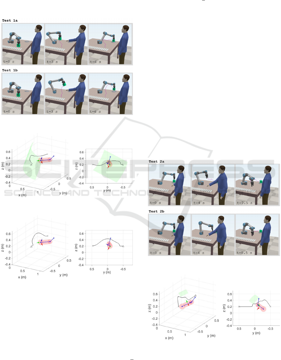
of the attractive cylinder influences the end-effector
passing on the side identified by the direction of the
𝑦
axis (green arrow). In comparison, the classical
approach with only repulsive velocities, identified as
Test 1b in Figure 12, produces an alternative path
above the human hand, as shown in Figure 14.
Figure 12: Frames of Test 1.
Figure 13: Alternative path of the end-effector in Test 1a.
Figure 14: Alternative path of the end-effector in Test 1b.
In Test 2, the human intercepts the robot planned
path with the forearm during the second phase of the
robot task. An attractive arc with 𝜃
=2𝜋/9 is
placed on the forearm, so that 𝑧
is aligned with the
line connecting the elbow to the hand and 𝑦
is
perpendicular to the plane defined by hand, elbow and
shoulder. The reason behind a narrow 𝜃
lies on the
coupling with the repulsive cylinder. In fact, due to
the same geometric primitives, the case 𝜃
≤𝜃≤
produces an attractive component that has the same
direction of the repulsive one. However, the use of a
small 𝜃
moves the attraction towards the ends of the
arc, as defined for −
≤𝜃<𝜃
. This effect forces
the robot to pass above the forearm, as shown in
Figure 15, Test 2a. The related end-effector path is
illustrated in Figure 16.
In comparison, the case with only repulsive
velocities is not able to produce an alternative path.
This is shown in Figure 15, Test 2b. The robot crosses
the forearm, but the repulsive direction does not drive
the end-effector upward. Moreover, the human
movement is more intrusive compared to Test 1 and
the robot gets trapped. The robot stops when the
minimum distance with the human envelope is less
than a safety margin equal to 0.05 𝑚. This can be
seen in Figure 17, where the human-robot minimum
distance and the end-effector velocity are plotted.
When the operator retracts the arm, the minimum
distance rises over the safety margin and the robot
continues its motion towards the home position.
Moreover, Test 2 shows the capability of the
attractive arc to drive the robot towards a preferred
direction, pointing out also a limitation of the
classical approach.
Figure 15: Frames of Test 2.
Figure 16: Alternative path of the end-effector in Test 2a.
ICINCO 2022 - 19th International Conference on Informatics in Control, Automation and Robotics
546
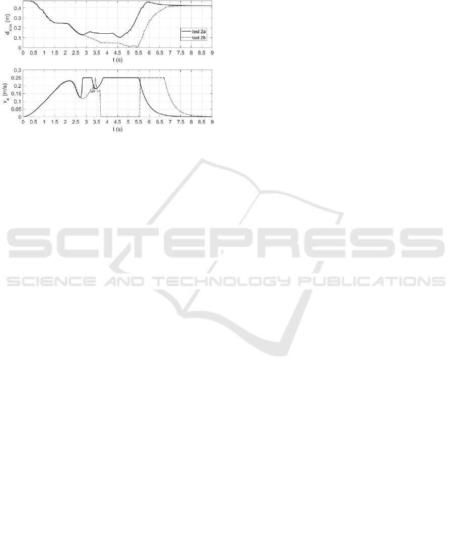
In fact, by observing the curves in Figure 17, it is
evident the increased efficiency in terms of task time,
as in Test 2a the robot reaches the home position 1 𝑠
before Test 2b. Notice that in each test the magnitude
of the end-effector velocity has been limited to
0.25 𝑚/𝑠 due to safety concerns.
Figure 17: Comparison of minimum distance and end-
effector velocity of Test 2a and Test 2b.
4 CONCLUSIONS
The state of the art on human robot collaboration
suggested that there is a lack of contributions on
conditioning collision-free robot trajectories
according to human preferences. In this work, an
effective solution based on attractive and repulsive
geometries opportunely placed around the human has
been proposed. The combination of repulsive volume
with attractive effects is novel. The attraction has
been related to cylindrical sectors, whose features can
be modified at will to fit the body part and to produce
attractive velocity components along preferred
directions.
To evaluate the effectiveness of the algorithm, a
simulation environment made of a collaborative robot
UR5 and a human dummy has been used. To simulate
human-like motion, the dummy is moved according
to data previously acquired by two Kinect sensors in
duplex configuration. A pick and place task has been
considered, as this can be a subtask of a collaborative
assembly. Results have shown that by placing
attractive cylindrical sectors on the hand rather than
on the forearm of the operator, the collision avoidance
path can be influenced in some way. The robot is
forced passing in front of the hand or above the
forearm during the avoidance manoeuvre. This allows
to choose a priori the collision avoidance direction.
Future works will regard the possibility to use
different attractive geometries, e.g. spherical sectors
and planes, and the experimental application in a real
world scenario to evaluate the robustness of the
proposed approach in different operating conditions.
REFERENCES
Byner, C., Matthias, B., & Ding, H. (2019). Dynamic speed
and separation monitoring for collaborative robot
applications – Concepts and performance. Robotics and
Computer-Integrated Manufacturing, 58(September
2018), 239–252. https://doi.org/10.1016/
j.rcim.2018.11.002
Chen, J.-H., & Song, K.-T. (2018). Collision-Free Motion
Planning for Human-Robot Collaborative Safety Under
Cartesian Constraint. 2018 IEEE International
Conference on Robotics and Automation (ICRA), 1–7.
https://doi.org/10.1109/ICRA.2018.8460185
Corrales, J. A., Candelas, F. A., & Torres, F. (2011). Safe
human – robot interaction based on dynamic sphere-
swept line bounding volumes. Robotics and Computer-
Integrated Manufacturing, 27, 177–185.
https://doi.org/10.1016/j.rcim.2010.07.005
Dragan, A. D., Bauman, S., Forlizzi, J., & Srinivasa, S. S.
(2015). Effects of Robot Motion on Human-Robot
Collaboration. In ACM/IEEE International Conference
on Human-Robot Interaction (pp. 51–58). ACM.
https://doi.org/10.1145/2696454.2696473
Flacco, F., Kroger, T., Luca, A. De, & Khatib, O. (2012). A
Depth Space Approach to Human-Robot Collision
Avoidance. IEEE International Conference on
Robotics and Automation.
ISO/TS 15066. Robots and Robotic Devices: Collaborative
Robots. (2016). International Organization for
Standardization. Geneva, Switzerland.
Kaldestad, K. B., Haddadin, S., Belder, R., Hovland, G., &
Anisi, D. A. (2014). Collision avoidance with potential
fields based on parallel processing of 3D-point cloud
data on the GPU. Proceedings - IEEE International
Conference on Robotics and Automation, 3250–3257.
https://doi.org/10.1109/ICRA.2014.6907326
Koppenborg, M., Nickel, P., Naber, B., Lungfiel, A., &
Huelke, M. (2017). Effects of movement speed and
predictability in human – robot collaboration. Human
Factors and Ergonomics in Manufacturing & Service
Industries, 27(4), 197–209. https://doi.org/
10.1002/hfm.20703
Krüger, J., Lien, T. K., & Verl, A. (2009). Cooperation of
human and machines in assembly lines. CIRP Annals -
Manufacturing Technology, 58(2), 628–646.
https://doi.org/10.1016/j.cirp.2009.09.009
Liu, C., & Tomizuka, M. (2016). Algorithmic Safety
Measures for Intelligent Industrial Co-Robots. 2016
IEEE International Conference on Robotics and
Automation (ICRA), 3095–3102. https://doi.org/
10.1109/ICRA.2016.7487476
Martinez-Salvador, B., Perez-Francisco, M., & Del Pobil,
A. P. (2003). Collision detection between robot arms
and people. Journal OfIntelligent and Robotic Systems,
38, 105–119. https://doi.org/10.1023/A
Mauro, S., Scimmi, L. S., & Pastorelli, S. (2017). Collision
avoidance algorithm for collaborative robotics.
International Journal of Automation Technology,
11(3), 481–489. https://doi.org/10.1007/978-3-319-
61276-8_38
A Novel Constrained Trajectory Planner for Safe Human-robot Collaboration
547

Melchiorre, M., Scimmi, L. S., Mauro, S., & Pastorelli, S.
P. (2021). Vision-based control architecture for
human–robot hand-over applications. Asian Journal of
Control, 23(1), 105–117. https://doi.org/10.1002/
asjc.2480
Melchiorre, M., Scimmi, L. S., Pastorelli, S. P., & Mauro,
S. (2019). Collison Avoidance using Point Cloud Data
Fusion from Multiple Depth Sensors: A Practical
Approach. 2019 23rd International Conference on
Mechatronics Technology, ICMT 2019.
https://doi.org/10.1109/ICMECT.2019.8932143
Merckaert, K., Convens, B., Wu, C. ju, Roncone, A.,
Nicotra, M. M., & Vanderborght, B. (2022). Real-time
motion control of robotic manipulators for safe human–
robot coexistence. Robotics and Computer-Integrated
Manufacturing, 73(July 2021), 102223. https://doi.org/
10.1016/j.rcim.2021.102223
Parigi Polverini, M., Zanchettin, A. M., & Rocco, P. (2017).
A computationally efficient safety assessment for
collaborative robotics applications. Robotics and
Computer-Integrated Manufacturing, 46(November
2016), 25–37. https://doi.org/10.1016/
j.rcim.2016.11.002
Pellegrinelli, S., Moro, F. L., Pedrocchi, N., Molinari
Tosatti, L., & Tolio, T. (2016). A probabilistic approach
to workspace sharing for human–robot cooperation in
assembly tasks. CIRP Annals - Manufacturing
Technology, 65(1), 57–60. https://doi.org/10.1016/
j.cirp.2016.04.035
Ragaglia, M., Zanchettin, A. M., & Rocco, P. (2018).
Trajectory generation algorithm for safe human-robot
collaboration based on multiple depth sensor
measurements. Mechatronics, 55(December 2017),
267–281.
https://doi.org/10.1016/j.mechatronics.2017.12.009
Safeea, M., Neto, P., & Bearee, R. (2019). On-line collision
avoidance for collaborative robot manipulators by
adjusting off-line generated paths: An industrial use
case. Robotics and Autonomous Systems, 119, 278–288.
https://doi.org/10.1016/j.robot.2019.07.013
Schmidt, B., & Wang, L. (2014). Depth camera based
collision avoidance via active robot control. Journal of
Manufacturing Systems, 33(4), 711–718.
https://doi.org/10.1016/j.jmsy.2014.04.004
Scimmi, L. S., Melchiorre, M., Mauro, S., & Pastorelli, S.
(2018). Multiple collision avoidance between human
limbs and robot links algorithm in collaborative tasks.
ICINCO 2018 - Proceedings of the 15th International
Conference on Informatics in Control, Automation and
Robotics, 2, 291–298. https://doi.org/
10.5220/0006852202910298
Scimmi, L. S., Melchiorre, M., Troise, M., Mauro, S., &
Pastorelli, S. (2021). A Practical and Effective Layout
for a Safe Human-Robot Collaborative Assembly Task.
Applied Sciences (Switzerland), 11(4).
Siciliano, B., Sciavicco, L., Villani, L., & Oriolo, G. (2009).
Robotics - Modelling, Planning and Control. Journal of
Chemical Information and Modeling.
Universal Robots. (n.d.). UR5 CB-Series Technical details.
Retrieved May 4, 2022, from https://www.universal-
robots.com/download-center/#/cb-series/ur5
Universal Robots. (2022). DH parameters for calculations
of kinematics and dynamics. Retrieved May 4, 2022,
from https://www.universal-robots.com/articles/ur/
application-installation/dh-parameters-for-
calculations-of-kinematics-and-dynamics/
Vicentini, F. (2021). Collaborative Robotics: A Survey.
Journal of Mechanical Design, Transactions of the
ASME, 143(4), 1–20. https://doi.org/10.1115/
1.4046238
Zanchettin, A. M., Rocco, P., Chiappa, S., & Rossi, R.
(2019). Towards an optimal avoidance strategy for
collaborative robots. Robotics and Computer-
Integrated Manufacturing, 59(June 2018), 47–55.
https://doi.org/10.1016/j.rcim.2019.01.015
ICINCO 2022 - 19th International Conference on Informatics in Control, Automation and Robotics
548
