
Control Strategy of Upper Limb Rehabilitation Exoskeleton based on
Impedance Control and Position Feedback
Yan Bo
a
and Wei Wei
b, *
School of Electrical and Electronic Engineering, Changchun University of Technology,
Yanan Main Street, Changchun, China
Keywords: Rehabilitation Robot, Impedance Control, Human Body Impedance Model.
Abstract: The upper limb rehabilitation exoskeleton was designed based on the human movement mode, and the
kinematics and dynamics of the exoskeleton were modeled by simulink. The double closed-loop control
system composed of impedance controller and position feedback was designed according to the control
requirements. Based on the movement requirements, The parameters were adjusted adaptively to meet the
design needs, and the conclusion was proved through simulation experiments.
a
https://orcid.org/0000-0001-5781-6025
b
https://orcid.org/0000-0001-8760-7400
1 INTRODUCTION
At present, with the improvement of living standards
and the increase of average life expectancy, the
number of people with movement disorders caused
by strokes and other causes is increasing
rapidly(Cheng 2019). Rehabilitation training is an
important recovery method for people with
movement disorders (Zhuo 2003), but traditional
rehabilitation training is highly dependent on
professionals (Sun 2019). The training method
assisted by rehabilitation robots has developed
rapidly in recent years (Lo 2010, Klamroth-
Marganska 2014). Studies have shown that
rehabilitation robots such as exoskeleton can play a
very helpful role in the rehabilitation training of
patients with movement disorders caused by stroke
(Connell 2014). The rehabilitation exoskeleton can
realize different types of rehabilitation training, such
as active and passive, through the cooperation of
man and machine. By simulating the daily motion
behavior of the human body, it helps patients to
realize the recurrence of daily activities, and helps
users to achieve muscle and nervous system
recovery by providing impedance or exercise
assistance, and restore the corresponding motor
functions (Yao 2019). In this regard, scholars have
conducted a lot of researches on rehabilitation
exoskeleton, the focus of which is the human-
computer interaction control method of exoskeleton
(Li 2008).
Due to the non-linear characteristics of the man-
machine coupling system, many scholars have
proposed different control strategies based on
different control theories. According to the extracted
human-computer interaction information, it can be
divided into two types: bio-signal-based human-
computer interaction and force/position information-
based human-computer interaction (Du 2018). Since
human body signals are difficult to extract and
susceptible to interference, signal processing in this
way is relatively cumbersome. The human-computer
interaction method based on force/position
information has the advantages of simple extraction
and clear physical meaning. The current research is
relatively mature. For example, Saglia et al. used
impedance control to adjust the compliance of the
ankle rehabilitation robot to achieve patient-assisted
training (Saglia 2013). However, the traditional
impedance control control method has fixed control
parameters and is effective for a single training
target, but it is difficult to meet different training
requirements. Aiming at the above problems, this
paper designs an exoskeleton control system that
adaptively adjusts impedance control parameters.
Bo, Y. and Wei, W.
Control Strategy of Upper Limb Rehabilitation Exoskeleton based on Impedance Control and Position Feedback.
DOI: 10.5220/0011370500003438
In Proceedings of the 1st International Conference on Health Big Data and Intelligent Healthcare (ICHIH 2022), pages 379-384
ISBN: 978-989-758-596-8
Copyright
c
2022 by SCITEPRESS – Science and Technology Publications, Lda. All rights reserved
379
2 EXOSKELETON MODEL
2.1 Exoskeleton Kinematics Model
In order to ensure the coordination of human-
machine movement, the exoskeleton and the human
body should adopt similar movement patterns and
structural designs. The upper limb exoskeleton
model with 2 rigid bodies and 4 free in series is used
as the research object. The shoulder joint and elbow
joint are used as the main joints for exercise
assistance. The four degrees of freedom of shoulder
internal rotation/external rotation, forward
flexion/posterior extension, outward
swing/adduction, and elbow joint flexion/posterior
extension are the design degrees of freedom. The
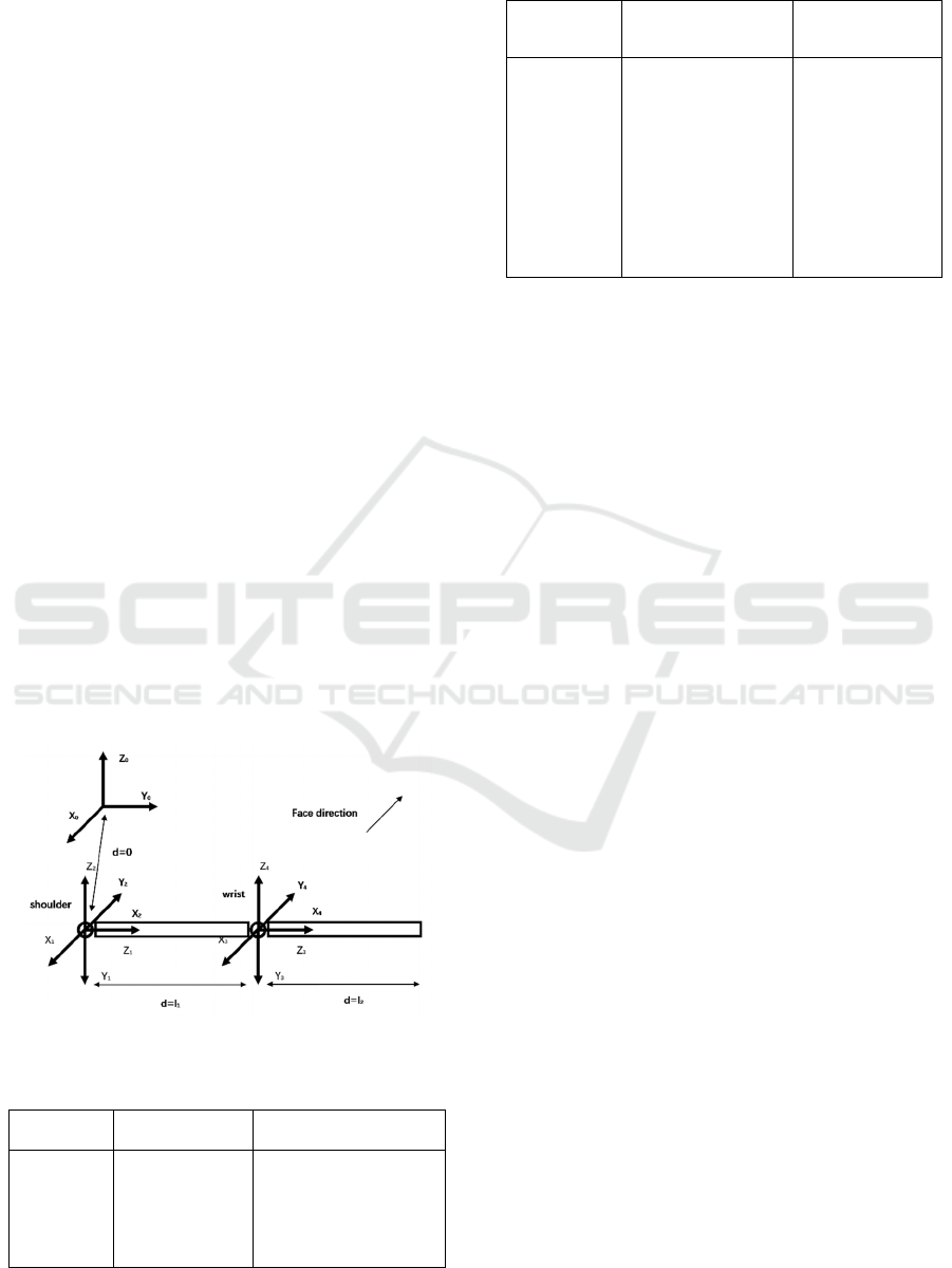
schematic diagram is shown in Fig 1. Among them,
the X
0
-Y
0
-Z
0
coordinate system is the base
coordinate system, and its coordinate origin
coincides with the shoulder joint point.
The exoskeleton uses flat extension to the right
as the initial state of motion, and the joint angle θ
1-4
represents the angle between it and the initial state,
where θ
1-4
corresponds to the flexion/extension,
extension/adduction, and rotation of the shoulder
joint, respectively. Internal/external rotation, elbow
flexion/extension four degrees of freedom. Since
there are two rotating shafts that coincide with the
joints, it is difficult to model with the D-H parameter
method. The kinematics model is established
directly by the principle of coordinate change. The
transformation method is shown in Table 1.
Figure 1: Schematic diagram of exoskeleton.
Table 1: Coordinate system change table.
Coordinate
system
0→1 1→2
Coordinate
system
change
method
Rotate around
the X-axis
square -pi/2 →
rotate around the
Z-axis square θ
1
Rotate around the Y-axis
square -pi/2→
rotate around the X-axis
square pi/2→
rotate around the Z-axis
square θ2
Table 1 (CONTINUED)
Coordinate
system
2→3 3→4
Coordinate
system
change
method
Rotate around the
Z-axis square -
pi/2→
rotate around the
X-axis square -
pi/2→
translate along the
Z-axis square l1→
rotate around the
Z-axis s
q
uare θ3
Rotate square
around Y axis -
pi/2→
rotate pi/2
around X axis→
rotate square
around Z axis
θ4
𝑇=𝑅𝑜𝑡
(
𝑋,−𝑝𝑖 2
⁄)
𝑅𝑜𝑡
(
𝑍,𝜃
)(
1
)
𝑇=𝑅𝑜𝑡
(
𝑌,−𝑝𝑖 2
⁄)
𝑅𝑜𝑡
(
𝑋,𝑝𝑖 2
⁄)
𝑅𝑜𝑡
(
𝑍,𝜃
)(
2
)
𝑇=𝑅𝑜𝑡
(
𝑍,−𝑝𝑖 2
⁄)
𝑅𝑜𝑡
(
𝑋,−𝑝𝑖 2
⁄)
∙
𝑇𝑟𝑎𝑛𝑠(𝑍,𝑙
)𝑅𝑜𝑡
(
𝑍,𝜃
)(
3
)
𝑇=𝑅𝑜𝑡
(
𝑌,−𝑝𝑖 2
⁄)
𝑅𝑜𝑡
(
𝑋,𝑝𝑖 2
⁄)
𝑅𝑜𝑡
(
𝑍,𝜃
)(
4
)
Where, 𝑇
represents the coordinate
transformation matrix from the coordinate to the nth
coordinate in the n+1 coordinate system. 𝑅𝑜𝑡
(
𝑎,𝜃
)
represents the transformation matrix that rotates θ
degrees around the coordinate axis a, and
𝑇𝑟𝑎𝑛𝑠(𝑍,𝑙
) represents the transformation matrix
that translates l1 toward the Z axis. Then the spatial
coordinates of the elbow joint and wrist joint in the
base coordinate system are
𝑋
,𝑌
,𝑍
,1
=𝑇
𝑇
𝑙
,0,0,1
(
5
)
𝑋
,𝑌
,𝑍
,1
=𝑇
𝑇𝑇𝑇
𝑙
,0,0,1
(
6
)
Where, [X
1
,Y
1
,Z
1
] is the coordinate of the elbow
joint, [X
2
,Y
2
,Z
2
] is the coordinate of the wrist joint,
and the speed of the joint points is
𝑉 = 𝜕𝑋 𝜕𝜃
⁄
∙𝑑𝜃 𝑑𝑡
⁄(
7
)
2.2 Exoskeleton Dynamic Model
In this paper, Lagrangian equations are used to
establish the exoskeleton dynamics model. The
model ignores the joint friction damping and the
movement deviation caused by the mechanism
mismatch. At the same time, the exoskeleton is
regarded as a pure rigid mechanism. Take the
shoulder joint as the origin of motion, and the o-xy
plane of the base coordinate system as the zero
potential energy surface. Assuming that the weight
of the boom mechanism is m1, the center of mass
and the origin of motion are l
1
, the weight of the
forearm mechanism is m
2
, and the distance between
ICHIH 2022 - International Conference on Health Big Data and Intelligent Healthcare
380

the center of mass and the elbow joint is l
2
. From the
Lagrangian equation
𝑇=
𝑑
𝑑𝑡
𝜕𝐿
𝜕𝜃
−
𝜕𝐿
𝜕𝜃
(
8
)
Among them, T is the joint torque and L is the
Lagrangian function, which is the difference
between the kinetic energy and the potential energy
of the system, namely
𝐿𝜃
,𝜃=𝐾𝜃
,𝜃−𝑃
(
𝜃
)(
9
)
Among them, K is the total kinetic energy of the
system, and P is the total potential energy of the
system. The exoskeleton is regarded as a
homogeneous rigid body to reduce the complexity of
the system. Then the rigid body can be equivalent to
the mass point at the center of mass of the rigid
body. From equation (7), the speed of the mass point
in various directions can be known, and the negative
semi-axis direction of the base coordinate Z axis is
taken as the gravity direction. Then
𝐿𝜃
,𝜃=(𝑚
𝑉
𝜃
,𝜃+𝑚
𝑉
(𝜃
,𝜃)) 2
⁄
−𝑚
𝑍
(
𝜃
)
+𝑚
𝑍
(
𝜃
)
𝑔
(
10
)
The standard form of its kinetic equation can be
expressed as
𝑀
(
𝜃
)
𝜃
+𝐶𝜃
,𝜃𝜃
+𝐺
(
𝜃
)
=𝑇
(
11
)
Among them, 𝑀
(
𝜃
)
represents the moment of
inertia of the exoskeleton, 𝐶𝜃
,𝜃 represents the
Geese force and centrifugal force terms of the
system, and 𝐺
(
𝜃
)
represents the gravity term
2.3 Human Body Impedance Model
The paper (Duchaine 2009) uses a spring model to
describe the human body impedance, and proposes a
human body impedance model. The concept is that
when the human body remains stationary in space,
the distance between the moving unit and the force
is linear. Namely
𝐹=𝐾𝑥+𝑏
(
12
)
This article uses this method to obtain the contact
force between the human body and the exoskeleton.
In the preliminary work of this research group, the
repeatability of human motion was verified, and the
results proved that for the same moving target, the
human body's multiple motion trajectories have a
high degree of similarity. The movement was
planned. Based on the above assumptions, it can be
considered that during movement, when the actual
route of the human body deviates from the
movement intention, a force will be applied in the
opposite direction of the deviation direction. Based
on the results of literature (Duchaine 2009), it is
assumed that the force of the device has a linear
relationship with the actual route and the size of the
motion intention, thereby simulating the human-
machine contact force in actual motion.
3 EXOSKELETON
CONTROLLER DESIGN
3.1 Design Requirements
The control design of the human rehabilitation
exoskeleton should meet the active and passive
training requirements of rehabilitation training, that
is, when the user is completely or partially disabled,
the exoskeleton provides additional torque to help
the patient complete the exercise goal. When the
user has active exercise ability, he should follow the
user's movement. At the same time, safety
requirements should be met, and when the contact
force is large, stop in time to ensure the safety of
users. In addition, it should have a certain degree of
flexibility to meet the needs of human-computer
interaction.
3.2 Impedance Control
Impedance control is a way to achieve indirect force
control by controlling the movement of the robot. Its
ultimate goal is neither to directly control the
movement of the system nor the contact force
between the system and the outside world, but the
dynamic relationship between the two. Make the
motion joints of the mechanical system exhibit the
dynamic characteristics of the second-order system
composed of spring-damping-mass, namely:
𝑀
𝜃
+𝐷
𝜃
+𝐾
𝜃
=𝜏
(
13
)
Among them, 𝑀
,𝐷
,𝐾
correspond to the set
mass, damping, and elastic coefficient respectively.
In order to make the impedance characteristics of
each joint independent of each other, 𝑀
,𝐷
,𝐾
are
generally designed as diagonal arrays, and 𝜃
is the
movement deviation angle. Combine it with
equation (11) to obtain a motion model including
impedance control.
Control Strategy of Upper Limb Rehabilitation Exoskeleton based on Impedance Control and Position Feedback
381
𝜏=𝑀
(
𝜃
)
𝜃
+𝐶𝜃
,𝜃𝜃
+𝐺
(
𝜃
)
+𝑀
(
𝜃
)
𝑀
𝐷
𝜃
+𝐾
𝜃
+𝐼−𝑀
(
𝜃
)
𝑀
𝜏
(14)
Among them, 𝜃
is the set joint angle, θ is the actual
joint angle, and I is the identity matrix.
3.3 Position Feedback
Because the feedback torque of the impedance
control part of the design controller is determined by
the actual joint angle and the user's own planned
joint angle. For the set trajectory and the actual
trajectory, it is actually an open-loop control. In this
case, in order to improve the controllability of the
exoskeleton, the joint angle and joint angular
velocity feedback are used to realize the position
feedback of the controller.
𝜏
=𝐾
𝜃
+𝐾
𝜃
(
15
)
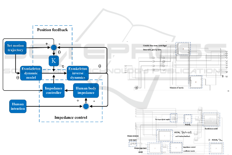
The controller block diagram is shown as in Fig.
2.
Figure 2. System control block diagram
3.4 Control Parameter Design
Based on the design function realization
requirements, the designed control model should
satisfy different motion feedback under different
motion assistance requirements. The overall system
feedback can be divided into impedance control
feedback based on contact force and position
feedback based on position information, namely
𝜏
=𝜏+𝜏
+𝜏
(
16
)
Where,
𝜏
is the total input of the controlled
torque, τ is the input of the calculation based on the
kinematics model,
𝜏
is the position feedback, and
𝜏
is the equivalent feedback of impedance
control. Based on the principle of impedance
control, under the influence of 𝜏
, the motion
trajectory will have an offset that tends to the human
body motion intention, and 𝜏
will cause the motion
trajectory to have an offset close to the set value.
Therefore, the feedback of 𝜏
can be controlled by
increasing the coefficient K. Control the strength of
the position feedback to affect the overall control
effect, thereby meeting the design requirements.
4 EXPERIMENT
Assuming that the length l1 of the exoskeleton arm
part is 0.35m, the weight is 4kg, the length l1 of the
forearm part is 0.25m, the weight is 4kg, and the
human body impedance coefficient is 6000N/m, the
exoskeleton model is established. Use simulink to
establish a dynamic model, as shown in Fig.3, build
a control model from the control structure shown in
Fig.2, as shown in Fig. 4
Figure 3. Exoskeleton dynamic model.
Figure 4. Overall control model.
The result of setting a larger position feedback
coefficient is shown in Fig 5. The actual motion
curve is close to the set value, and the contact force
is larger. The result of setting a smaller position
feedback coefficient is shown in Fig 6. The actual
motion curve is close to the intention curve, and the
contact force is small. The result of setting the
ICHIH 2022 - International Conference on Health Big Data and Intelligent Healthcare
382
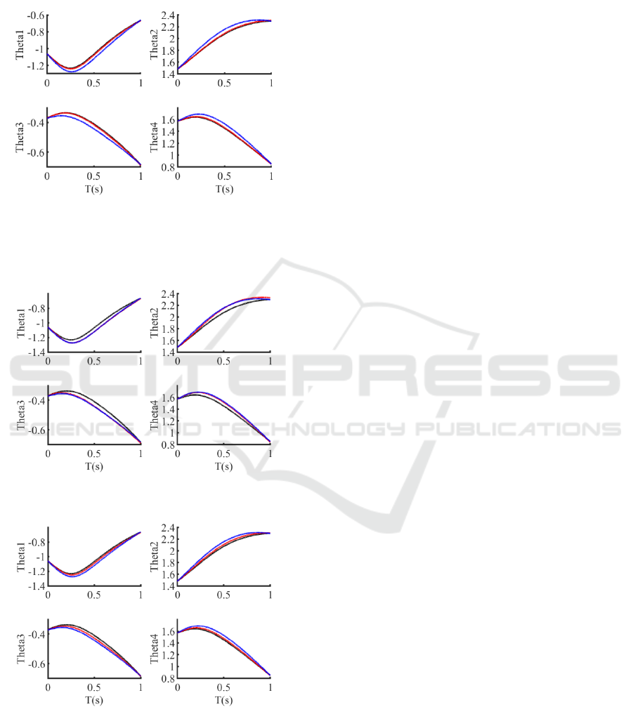
position feedback coefficient in the middle is shown
in Fig 7. The actual motion curve is between the
intention curve and the set curve, and the contact
force is moderate.
Figure 5. Oscilloscope waveform (from top to bottom are
θ1-4, the black curve is the set rotation angle, the red is the
actual rotation angle, and the blue line is the intention of
the human body)
Figure 6. Oscilloscope waveform
Figure 7. Oscilloscope waveform
5 CONCLUSIONS
The simulation experiment proves that by adjusting
the position feedback coefficient, the control can be
switched between different performances. The
impedance control coefficient determines the upper
limit of the closeness between the actual motion
curve and the human body intention curve. The
position feedback coefficient can be adjusted to
adjust the closeness between the actual curve and the
intention curve or the set curve to achieve different
human-computer interaction requirements.
REFERENCES
Cheng Siyuan, Chen Guangfeng. Research and Simulation
of fuzzy PID control for lower limb rehabilitation
exoskeleton robot [J]. Measurement and control
technology, 2019, 038 (012): 22-28.Chinese
Connell L A, McMahon N E, Harris J E, et al. A formative
evaluation of the implementation of an upper limb
stroke rehabilitation intervention in clinical practice: a
qualitative interview study[J]. Implementation
Science, 2014, 9(1): 1-12.
Du Yihao, Qiu Shi, Xie Ping, et al. Adaptive Human-
Computer Interaction Control Strategy for lower limb
rehabilitation robot [J]. Journal of automation, 2018,
44 (4): 743-750 Chinese
Duchaine V, Gosselin C. Safe, stable and intuitive control
for physical human-robot interaction[C]//2009 IEEE
International Conference on Robotics and Automation.
IEEE, 2009: 3383-3388.
Klamroth-Marganska V , Blanco J , Campen K , et al.
Three-dimensional, task-specific robot therapy of the
arm after stroke: a multicentre, parallel-group
randomised trial.[J]. The Lancet Neurology, 2014,
13(2):159-166.
Li Qingling, sun lining, Du Zhijiang. Analysis and
Research on the development status of upper limb
rehabilitation robot [J]. Mechanical design, 2008 (09):
1-3 Chinese
Lo A C, Guarino P D, Richards L G, et al. Robot-assisted
therapy for long-term upper-limb impairment after
stroke[J]. New England Journal of Medicine, 2010,
362(19): 1772-1783.
Saglia J A , Tsagarakis N G , Dai J S , et al. Control
Strategies for Patient-Assisted Training Using the
Ankle Rehabilitation Robot (ARBOT)[J].
IEEE/ASME Transactions on Mechatronics, 2013,
18(6):1799-1808.
Sun dingyang, Shen Hao, Guo Chao, et al. Design and
control of rope driven flexible upper limb exoskeleton
robot [J]. Robot, 2019, 41 (6): 834-841.Chinese
Tu Yao, Zhu aibin, song Jiyuan, et al. Human computer
interaction force adaptive admittance control of lower
limb exoskeleton rehabilitation robot [J]. Journal of
Control Strategy of Upper Limb Rehabilitation Exoskeleton based on Impedance Control and Position Feedback
383

Xi'an Jiaotong University, 2019, 053 (006): 9-16
Chinese
Zhuo Dahong. Chinese rehabilitation medicine [M].
Huaxia publishing house, 2003.Chinese
ICHIH 2022 - International Conference on Health Big Data and Intelligent Healthcare
384
