
Design and Analysis of Learning Case based on Knee Rehabilitation
Training Device
Ying Chang
Jilin Agricultural Science and Technology University, Jilin, China
Keywords: Case Analysis, Knee Joint Rehabilitation Training Device, Structural Design.
Abstract: With the aging of population, the increase of physical diseases such as stroke and transportation, the number
of patients with limb dyskinesia, especially knee dyskinesia, increases sharply. This paper introduces the
structural design and analysis of knee joint rehabilitation training device, which can maximize the recovery
of patients' motor function, provide the basis for rehabilitation doctors to evaluate the effect of rehabilitation
training and formulate rehabilitation plan, reduce the labor intensity of rehabilitation doctors, and improve
the rehabilitation efficiency. Through the case design and analysis of knee rehabilitation training device,
students' mechanical design calculation ability can be cultivated, and students' understanding and
application of basic knowledge can be enhanced.
1 INTRODUCTION
In order to change the situation of relying solely on
rehabilitation physicians to assist patients with knee
joint to carry out rehabilitation training, further
improve the efficiency of rehabilitation training, and
improve the rehabilitation effect, the rehabilitation
robot technology combining robotics and
rehabilitation medicine has increasingly become a
research hotspot of scholars at home and abroad
(Wang, Chang, Zhu 2019). So far, many scholars at
home and abroad have done a lot of research work
on the rehabilitation robot, especially the lower limb
knee joint rehabilitation robot, and have made many
achievements (Weber-Spickschen, Colcuc, Hanke, et
al. 2017, Mavroidis, Bonato 2007, Koller-Hodac,
Leonardo, Walpen, et al. 2011, Koller-Hodac,
Leonardo, Walpen, et al. 2010, Smart portable
rehabilitation devices 2005, Adnan, Karamat,
Kamal, et al. 2014).
According to the rehabilitation training posture
of patients, lower limb rehabilitation institutions can
be divided into two categories: horizontal CPM
machine and vertical lower limb auxiliary
rehabilitation device (Hu 2009). At present, the most
commonly used lower limb rehabilitation device is
the horizontal CPM machine, and the lower limb fit
adopts the lap type. Patients can use the lying
position after operation, and put the lower limb
directly on the CPM mechanism for training. The
concept of CPM was put forward by Salter, a
Canadian Orthopaedic expert, after a lot of
experiments in the 1970s. It is the use of special
equipment by mechanical or electronic devices to
drive or maintain part of the limb movement, so that
the joint for a long time of slow passive movement,
so that the combination of treatment and
rehabilitation, can relieve pain, improve joint range
of motion, prevent joint contracture and adhesion. It
can promote the regeneration and repair of intra-
articular cartilage, and is conducive to the recovery
of limb function (Li, Li 2007). CPM machine
training is a mature method for postoperative limb
continuous exercise training (Morris 1995). The
development of CPM has gone through three
historical stages. Salter first put forward the concept
of CPM in 1975 after trial and clinical research. In
1982, Coutts et al. Applied CPM device to human
rehabilitation training. In 1992, McInnes et al.
Started a prospective study to explore the application
effect of CPM in different situations (Ning, Xu, Li
2007). At present, CPM technology has been widely
accepted in orthopedic rehabilitation field in China,
and its application scope is becoming wider and
wider.
This device can be worn on the lower limbs of
patients, and can fit closely with the legs. The parts
of the mechanism that fit the lower limbs are
generally made of light and soft materials, which are
Chang, Y.
Design and Analysis of Learning Case based on Knee Rehabilitation Training Device.
DOI: 10.5220/0011370900003438
In Proceedings of the 1st International Conference on Health Big Data and Intelligent Healthcare (ICHIH 2022), pages 391-395
ISBN: 978-989-758-596-8
Copyright
c
2022 by SCITEPRESS – Science and Technology Publications, Lda. All rights reserved
391

closely combined with the legs, so it can achieve
more accurate angle control. The wearable structure
makes the training flexible, and rehabilitation
training can be carried out in standing, sitting and
lying positions. In this kind of research, pneumatic
artificial muscle and cylinder are more selected as
actuators, which can provide certain flexibility and
relatively high safety. However, due to the short
stroke of pneumatic artificial muscle and cylinder,
the rehabilitation angle of this kind of rehabilitation
mechanism is relatively small, which can not meet
the requirements of large angle rehabilitation, so it is
often used in gait training and disability assistance.
This kind of device is complicated and inconvenient
to wear. Because the vertical lower limb auxiliary
rehabilitation mechanism is mostly wearable, it fits
closely with the human body, and the bending angle
of the mechanism is equal to the bending angle of
the human joint, which can achieve accurate control.
Moreover, it uses pneumatic artificial muscle or air
cylinder as the driver, which has good flexibility and
can meet the safety when contacting with people.
Due to the limitation of rehabilitation posture, the
vertical lower limb auxiliary rehabilitation
mechanism can not be used for postoperative
rehabilitation, and the rehabilitation angle is very
small, so it is mostly used for auxiliary rehabilitation
training. But the wearable mechanism is generally
more complex, and to distinguish between the left
and right legs, wearing trouble, not very practical.
Through such analysis and data searching, students
can understand the cutting-edge technology, master
the specific application and implementation process
of mechanical design, design the corresponding
design scheme, reasonably analyze the design
calculation, and cooperate with the team to complete
the design and rationality analysis. In this process,
design calculation will be checked repeatedly, which
can cultivate one's design calculation ability and
craftsmanship spirit.
Mechanical structure design is the basis of
rehabilitation training for rehabilitation robot. This
paper mainly analyzes the structure design of knee
rehabilitation robot, and designs a reasonable
structure of rehabilitation robot. Through the
introduction of this case, students' craftsmanship
spirit can be cultivated in the process of design and
calculation.
2 DESIGN AND CALCULATION
OF KNEE REHABILITATION
TRAINING DEVICE
2.1 Weight and Height Data
The relationship between weight and height is as
follows
Normal weight
W
2
=H-110(kg) (1)
Ideal weight
W
L
=H-100(kg) (2)
If a person's weight is often lower than or higher
than 10% of the normal weight, it is an abnormal
state.
2.2 Calculation of Body Volume and
Surface Area
When the body weight is 50-100kg, the body
volume and surface area can be calculated according
to the following formula.
Calculation of human body volume
V = 1.015W-4.937 (3)
Where V is the volume of human body (m
3
); W
is the body weight (kg).
Through the design and calculation of human
body data, students' learning ability and application
ability of interdisciplinary knowledge can be
cultivated.
2.3 Weight and Height Data
According to ergonomics, the knee joint is rotated to
achieve the effect of rehabilitation treatment. The
weight of the human body accounts for about 35%
of the total weight of the human body. The average
person's weight is generally between 50kg-100kg,
and the m
leg
is 17.5kg-35kg. The rotation times of
knee rehabilitation treatment cycle is n
2
= 6 r/min,
the transmission ratio is I = 3. The stepping motor
with rated voltage of 220 V and rated power of 20 W
is selected.
2.4 Structural Design of Belt Drive
(1)Determination of calculated power P
ca
P
ca
=Ka·P=1.0 X 20W=20W (4)
ICHIH 2022 - International Conference on Health Big Data and Intelligent Healthcare
392

Among them, the rehabilitation robot works 4-6
hours a day, so the working condition coefficient Ka
= 1.0.
(2)Determination of V-belt pattern
Check the mechanical engineering manual and
select a-belt by P
ca
and n
2
.
(3)Determine the reference diameter of the
pulley and check the belt speed
The datum diameter d
d1
of the primary pulley is
75mm.
Check the belt speed according to the formula:
V=
×
=
××
×
m/s=0.07m/s
Where n
1
= I = 18r / min.
Because the belt wheel speed is required to be
suitable for human knee rehabilitation treatment, the
belt speed of 0.07m/s can ensure human safety and
the stability of the machine.
Calculate the reference diameter of large pulley
d
d2
=i·d
d1
(5)
Select standard diameter d
d2
= 150 mm.
2.5 Determine the Center Sistance and
Reference Length of V-pulley
(1) Primary selection with formula a
0
0.7(d
d2
-d
d1
)≤a
0
≤2(d
d1
+d
d2
) (6)
Therefore, primary a
0
= 400mm.
(2) Calculate the required base length of the tape
a≈2 a
0
+
×
d
+d
+
(
)
(7)
a =[2 × 400+ 2π × ( 75+150 ) + ×
1100 1156
2
−
]mm
≈1156mm
Look up the table and select the datum diameter
1100mm.
(3) Checking the wrap angle on the small pulley
α
1
≈180 º﹣(d
d2
-d
d1
)
.º
=180 º-(150-75)
×
.º
≈168 º>120 º
(4) The number Z of design bands
A single V-belt is used, and the number of V-
belts is 1.
From d
d1
= 75mm, n
1
= 18r / min, P
0
= 0.26kw is
obtained. According to n
1
= 18r / min, I = 2, ∆P
0
=
0.05kw is obtained. Look up the table to get K α=
0.98,K
l
=0.91。
The initial tension F of a single belt is obtained
from the formula
F
0
=500
(.
)
+qv
=67N
According to the table, the mass per unit length
of type a belt q = 0.105kg/m.
(5) Calculate the axial force F
P
F
P
=2zF
0
sin
=2×1×67×sin
º
=134N
(6) Design conclusion
The common V-belt of type A is selected, the
datum length of the selected belt is 1100mm, the
datum diameter of the pulley d
d1
= 75mm, d
d2
=
150mm, the center distance is controlled at about a =
400mm, and the initial tension of a single belt F
0
=
134 N. The final CATIA design is shown in Fig.1.
Figure 1: Belt drive structure.
3 DESIGN AND CALCULATION
OF KNEE REHABILITATION
TRAINING DEVICE
3.1 Design and Calculation of Thigh
Bar
The average thigh width of healthy adult men is 150
mm-170 mm, and the calf width is 100 mm-120 mm.
Therefore, according to the ergonomic structure
design, the modeling sketch in CATIA software is
shown in Fig.2.
Model design of main parts of lower limb
rehabilitation robot.
Figure 2: Thigh bar.
Design and Analysis of Learning Case based on Knee Rehabilitation Training Device
393
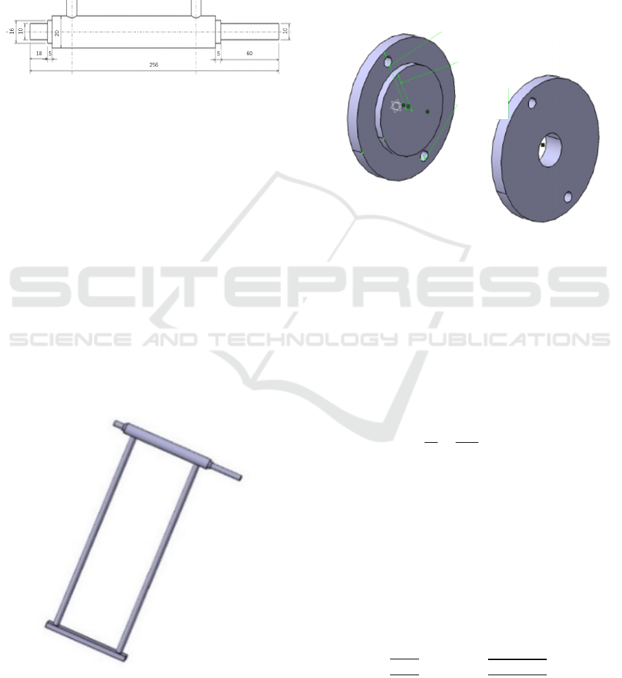
3.2 Design and Calculation of Spindle
The function of the main shaft is to connect the
pulley and the leg bar. Under the support of the leg
bar and the bearing, the main shaft can rotate and
transmit the motion of the motor to the leg bar, so as
to drive the rotation of the leg bar and realize the
purpose of circular rotation. The sketch of the
spindle is shown in Fig.3.
Figure 3: The spindle.
Bearing, end cover and large pulley are installed
at 60mm part of left end. In order to save materials
and simplify the design, the shank part is directly
welded to the spindle part to achieve better human-
computer interaction.
3.3 Design and the Design of Leg Bar
of Spindle
The shank rod is connected with the main shaft by
welding, so that it can be better stressed and
manufactured. According to the weight and size of
the human body, the shank rod adopts a cylinder
with a diameter of 10 mm and can be made of
aluminum alloy with a length of 400 mm. The back
end is connected by plate and welded, so that the
human body can step on or tie on the leg during
training. The leg bar is shown in Fig.4.
Figure 4: The design of leg bar.
3.4 Design of Bearing End Cover
The function of the bearing end cover is to prevent
the axial movement of the bearing, so the end cover
is used for axial positioning. Bearing end cover is
divided into two kinds, front cover and rear cover, so
it needs to be designed and processed separately.
According to the maximum outer diameter 40mm
and inner diameter 32mm of the thigh bar, the
design is carried out. The two end caps are shown in
Fig.5.
Figure 5: Bearing end cover.
3.5 Selection of Bearings
The above analysis shows that the axial force F =
134N, the pressure exerted by human legs is about F
= 116N, through the working state of the bearing,
the radial force F
r
= 250N, the axial force F
a
= 60N.
And use deep groove ball bearing.
(1) To find the ratio of F
a
and F
r
, there is a
formula:
F
F
=
60
250
=0.24
According to the bearing manual, when e = 0.24,
X= 0.56, Y= 1.8.
(2) Preliminary calculation of the equivalent
dynamic load P, where the working factor f
d
= 1.0
P= f
d
(XF
r
+YF
a
)=1.0×(
0.56×250+1.8×60)N =248N
(3) According to the formula, the basic rated
dynamic load of the bearing is calculated
C=P
= 248 ×
××
N =870N
ICHIH 2022 - International Conference on Health Big Data and Intelligent Healthcare
394

It is assumed that the use time of the lower limb
rehabilitation robot is 4000 hours. According to the
bearing manual, 6200 bearing is used. Deep groove
ball bearing with inner diameter d = 10 mm, outer
diameter D = 32 mm and width B = 10 mm.
3.6 Force Analysis
According to the analysis of the operation of the
lower limb rehabilitation machine, the motor applies
torque on the small pulley, and the small pulley
drives the belt to rotate, so as to drive the large
pulley to rotate. The movement and force are
transmitted through the key and act on the main
shaft to realize the rotation of the main shaft.
Therefore, the rigid constraint is set through the part
connected by the key, and is applied to the face
corresponding to the key. There are many ways of
modal extraction, and block Lanczos method is used
in this paper.
The natural frequency of the assembly body is
determined by its structure. After modal analysis, the
vibration of the shaft is mainly concentrated in the
middle, which will swing left and right. The
maximum frequency of the sixth mode is 73.442Hz.
The vibration mainly includes the rotation of the
spindle, left and right swing, and the swing of the
spindle base along the Z axis. The minimum
frequency is 25.111Hz. The mechanism can work
normally.
4 CONCLUSIONS
When introducing these ideological and political
breakthroughs, try not to express the teachers' own
views directly, and use more cases, facts and
phenomena to inspire students to think, the effect
will be better. After practice, students are easy to
accept the actual case and video. Through practice, it
is found that in the process of design, calculation
and analysis of knee joint rehabilitation training
device, students have cultivated the ability of
independent thinking, analysis, problem-solving and
interdisciplinary learning, and cultivated their
craftsmanship spirit. Therefore, the actual design
and calculation of cases to explain knowledge points
can better help students understand and apply
knowledge.
ACKNOWLEDGEMENTS
This research was supported by Jilin Agricultural
Science and Technology University 's 2020 school-
level "Curriculum Ideological and Political" teaching
reform curriculum project-mechanical design basis.
REFERENCES
Wang L , Chang Y , Zhu H . Internal Model Control and
Experimental Study of Ankle Rehabilitation Robot[J].
Robotica, 2019:1-17.
Weber-Spickschen T S , Colcuc C , Hanke A , et al. Fun
During Knee Rehabilitation: Feasibility and
Acceptability Testing of a New Android-Based
Training Device[J]. The Open Medical Informatics
Journal, 2017, 11(1):29-36.
Mavroidis P , Bonato I . Design, Control and Human
Testing of an Active Knee Rehabilitation Orthotic
Device[C]// Proceedings 2007 IEEE International
Conference on Robotics and Automation. IEEE, 2007.
Koller-Hodac A , Leonardo D , Walpen S , et al. Knee
orthopaedic device how robotic technology can
improve outcome in knee rehabilitation[J]. IEEE
International Conference on Rehabilitation Robotics :
proceedings, 2011, 2011:5975347.
Koller-Hodac A , D Leonardo, Walpen S , et al. A novel
robotic device for knee rehabilitation improved
physical therapy through automated process[C]// IEEE
Ras & Embs International Conference on Biomedical
Robotics & Biomechatronics. IEEE, 2010.
Smart portable rehabilitation devices[J]. Journal of
NeuroEngineering and Rehabilitation, 2005, 2(1):1-15.
Adnan M , Karamat A , Kamal N , et al. Design of Gear
Bearing Drive (GBD) Based Active Knee
Rehabilitation Orthotic Device (AKROD)[C]// First
International Young Engineerings Convention (IYEC-
2014). 2014.
Hu Haiyan. Research on structure and control technology
of compliant knee joint rehabilitation device. Nanjing
University of technology, 2009
Li Yi, Li Ziqing. Research progress of CPM on
rehabilitation after total knee arthroplasty. Journal of
Yangtze University (self SCIENCE EDITION),
science and engineering volume, 2007,04:157-160 +
178
Morris J. The Value of Continuous Passive Motion in
Rehabilitation Following Total Knee Replacement.
Physiotherapy, 1995, 81(9):557-562.
Ning Lixin, Xu Yan, Li Dongwen. Application progress of
continuous passive motion after total knee arthroplasty
[J]. Chinese Journal of rehabilitation medicine,
2007,03:286-288
Design and Analysis of Learning Case based on Knee Rehabilitation Training Device
395
