
The Effect of Seismic Masses in Calculation of a 17 Multi-story
Concrete Structure
Daud Rahmat Wiyono
a
, Roi Milyardi
b
, Yosafat Aji Pranata
c
and Robby Y. Tallar
d
Department of Civil Engineering, Maranatha Christian University, Jl. Surya Sumantri 65, Bandung, Indonesia
robby.yt@eng.maranatha.edu
Keywords: Mass Source, Self and Specified Mass, from Loads, Equivalent Lateral Force, Story Shear, Story Drift.
Abstract: The seismic weight according to code will be used for seismic calculation and defined by mass source. The
application in ETABS has a 3-ways to define seismic mass: 1. From self and specified mass, 2. From loads.
3. From self and specified mass and loads. If the mass source is not defined properly, seismic forces will not
be calculated correctly and so the base shear value will also be incorrect. The purpose of this article is to
obtain the mass source from 3-ways in ETABS which is near to the manually calculated Mass and its effects.
The case study is a 17 multi-story building
,
, and from the results of the analysis and discussion it is concluded
that: the lowest time period, equivalent lateral force, story shear, story drift are the ‘From self and specified
mass’, followed by the ‘From load with DL+0.5 LL’. Next is the ‘Self and specified mass and load with
DL+0.5 LL’, and the last is ‘Self and specified mass and load with DL+ LL’. The value of ‘From load with
DL+0.5 LL’ is near to the manually calculated Mass with ‘DL+LL’, and thus corresponds to the
recommendation by ASCE 7–10.
1 INTRODUCTION
Mass source is a seismic weight according to code
and performed for seismic analysis. ASCE 7–10
requires the effective seismic weight including dead
load and other load, in this case other load is LL
reduction, so the value of reduction factor f is for LL
is determined. The load here will be used for seismic
calculations. In the application of software ETABS
there are 3 ways to define seismic mass: 1. From self
and specified mass, 2. From loads. 3. From self and
specified mass and loads.
Each choice has different consequences in
inputting Self weight, Dead load and Live load. For
example if From loads is chosen then the load S can
be assigned that refer to dead weight type (self-weight
included) and also the live load cases as per code with
the appropriate factor based on governing condition
(Computers and Structures Inc., n.d.).
The purpose of this article is to obtain the mass
source with a near to mass calculated manual from 3-
a
https://orcid.org/0000-0002-9130-6149
b
https://orcid.org/0000-0003-3025-1356
c
https://orcid.org/0000-0002-7828-124X
d
https://orcid.org/0000-0001-7307-3348
ways option in ETABS. The case study is a 17 multi-
story building where until the 10
th
story, the mass
becomes one mass and from the 11
th
to the 17
th
story,
the mass becomes 2-tower and the structure will be a
dual system.
ASCE 7–10 use ‘DL + 0.25 LL’ for seismic
masses, which LL for gravity combination can reduce
with factor 0.5. The seismic weight/mass that is
calculated using ETABS is then verified using an
analytical method which is called Mass calculated
manual. Self-weight has default of ‘DL + f LL’,
Specified Load patterns must select ‘DL + f LL’, and
additional mass due to surface loads line loads.
In ETABS consider full (100%) of dead load and
25% of live load (less than 3kN/m
2
), and if the live
load exceeds 3kN/m
2
then the mass source will be full
(100 %) of dead load and 50 % of live load. Usually
only full of dead load is enough for normal buildings,
but needed to consider all the Live loads and Dead
loads that are permanent. For example permanent
mechanical equipment as live load then consider
184
Wiyono, D., Milyardi, R., Pranata, Y. and Tallar, R.
The Effect of Seismic Masses in Calculation of a 17 Multi-story Concrete Structure.
DOI: 10.5220/0010747800003113
In Proceedings of the 1st International Conference on Emerging Issues in Technology, Engineering and Science (ICE-TES 2021), pages 184-189
ISBN: 978-989-758-601-9
Copyright
c
2022 by SCITEPRESS – Science and Technology Publications, Lda. All rights reser ved

them in mass source too. If a portion of live load is
assumed to be sustained for example where LL is
heavy like in malls, a portion of LL should also be
considered. So, any load that is deemed to be
permanent needs to be considered in seismic
calculation (Akis, 2004; Nageh, 2007).
These 3-ways choices each have the purpose to
input the load cases in each choice. Everyone can use
each 3-way choice with different load cases. The load
option is the one generally recommended by people
familiar with ETABS. The reason is because the
default “From self and specified mass” option means
that additional mass has to be manually assigned, and
that involves unit conversion for mass assignments.
The third option “From self and specified mass
and loads” is dangerous because many users tend to
include the dead self-weight in that list, thereby
double counting self-weight in the mass model. The
users can detect it in the warning while checking the
model showing the sentence “Mass source has both
element self-mass and a load pattern with a self-
weight multiplier greater than zero. This may result
in duplicated self-mass. If it is true, while checking
the model it will show the sentence “Model has been
checked”, and no warning messages were generated.
2 LITERATURE STUDY
Mass values consist of structural elements which
have volume and material density. In dynamic
analysis, mass translation and rotation with
acceleration to create inertial forces. For the purpose
of estimating seismic loads standard ASCE 7-10
requires calculating the effective seismic weight
which includes dead load, partitions and permanent
equipment, plus 25% of the floor live load in areas
used for storage (MacLeod, 1970; Somers, 2012;
Wight & MacGregor, 2012).
This contribution of live load as inertia seems to
be correlated with the low likelihood that live load
objects be present at the time of the designed
earthquake. However, for storage and some
commercial facilities live loads may continuously be
present and even exceed the dead load. Seismic mass
source is a parameter that used both for calculation of
seismic loads using Equivalent Lateral Force Method
and Responses Spectrum Analysis (American Society
of Civil Engineering, 2010; Atkins Structural
Department, 2007; Budiono & Supriatna, 2011;
Wiyono, R.D., Roi, C. M., & Lesmana, 2018).
Mass source is the structural weight and the
seismic loads are calculated based on the specified
mass of the building. ASCE 7/IBC requires for
another load as storage which is 0.25LL (not be
included in the effective seismic weight if increasing
of storage loads adds no more than 0.05, garages and
parking need not be included in the effective seismic
weight. Partition weight (10 psf) is required and the
weight of operation of permanent equipment. The
loading combination of 1.2D + E + 0.5L + 0.25S for
all occupancies in accordance with Table 4-1 ASCE
7–10 less than or equal to 4,79kN/m
2
.
3 ANALYTICAL MODEL
In this case study, a 17 multi-story building with two
elevator shafts in the left side and the right side of
floor plan building load has been calculated from the
code (American Society of Civil Engineering, 2010;
Badan Standarisasi Nasional, 2012). The mass source
until the 10th story is one mass. After that from the
11
th
to the 17
th
floor, the mass will become two
towers. The 3D structure given in Figure 1 shows the
plan of each floor.
(1a) 3D building model (1b) 1
st
-4
th
Floor Plan
(1c) 5
th
-6
th
Floor Plan (1d) 7
th
-17
th
Floor Pla
n
Figure 1: Building model and floor plane data.
4 RESULTS AND DISCUSSION
Table 1 shows the manually calculated Mass and in
Table 2 is shown the time periods. The lowest time
period is ‘From self and specified mass’, after that
‘From load with DL + 0.5 LL’, next is the ‘Self and
specified mass and load with DL + 0.5 LL’, and the
last is ‘Self and specified mass and load with 1 LL’.
From this table can be seen that the period of Mass
calculated manual DL + LL is near to From load with
DL + 0.5 LL.
The Effect of Seismic Masses in Calculation of a 17 Multi-story Concrete Structure
185
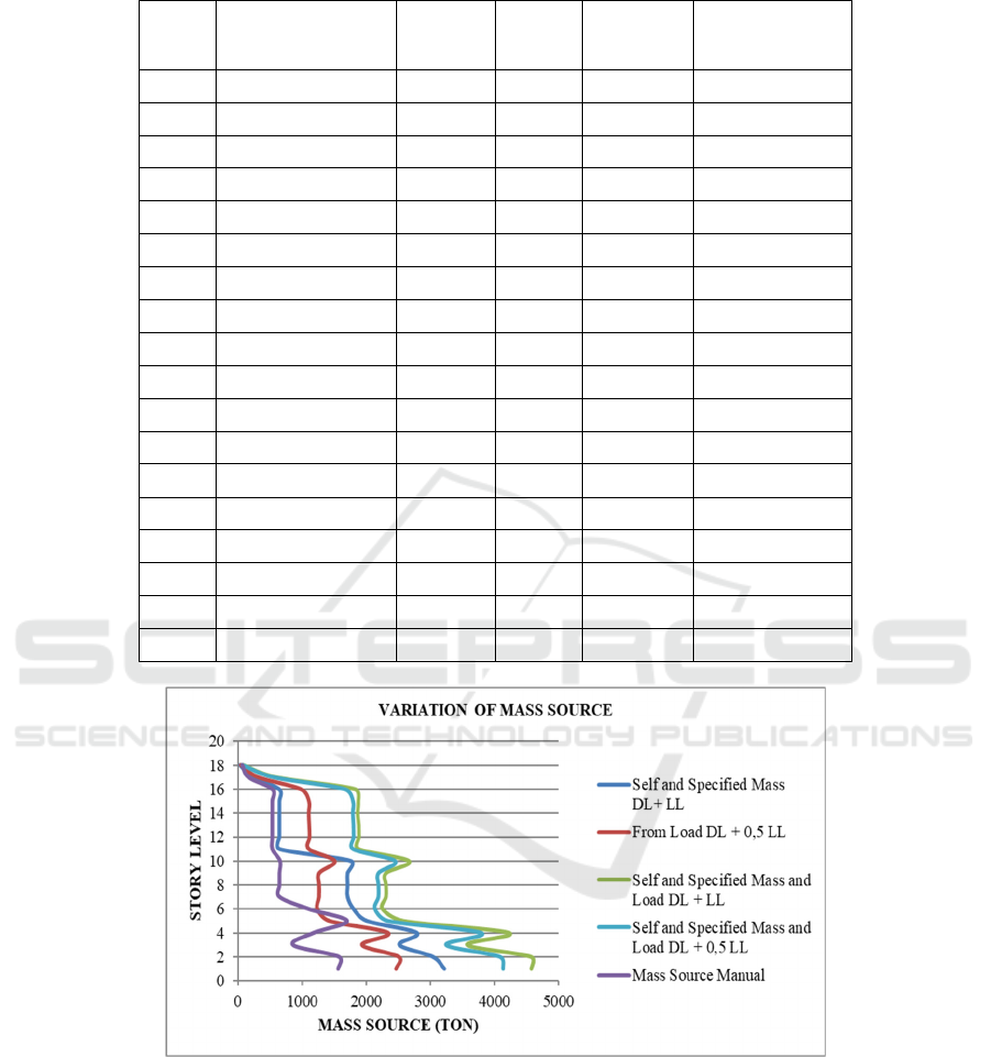
Table 1: Manual Calculation of Mass.
Floor
Self-Weight (DL)
(kg/m
2
)
SDL
(kg/m
2
)
LL
(kg/m
2
)
Total
Area
(
m
2
)
Total Weight
(kg)
17 27072 150 250 94 64672
16 65952 150 250 229 157552
15 222912 150 250 774 532512
14 222912 150 250 774 532512
13 222912 150 250 774 532512
12 222912 150 250 774 532512
11 222912 150 250 774 532512
10 222912 150 250 774 532512
9 273600 150 250 950 653600
8 269856 150 250 937 644656
7 269856 150 250 937 644656
6 269856 150 250 937 644656
5 338112 150 500 1174 1101212
4 522144 150 500 1813 1700594
3 360864 150 500 1253 1175314
2 262368 150 500 911 854518
1 608904 0 500 1933 1575404
0 642132 0 500 1836.2 1560232
Figure 2: Variation of mass source.
ICE-TES 2021 - International Conference on Emerging Issues in Technology, Engineering, and Science
186
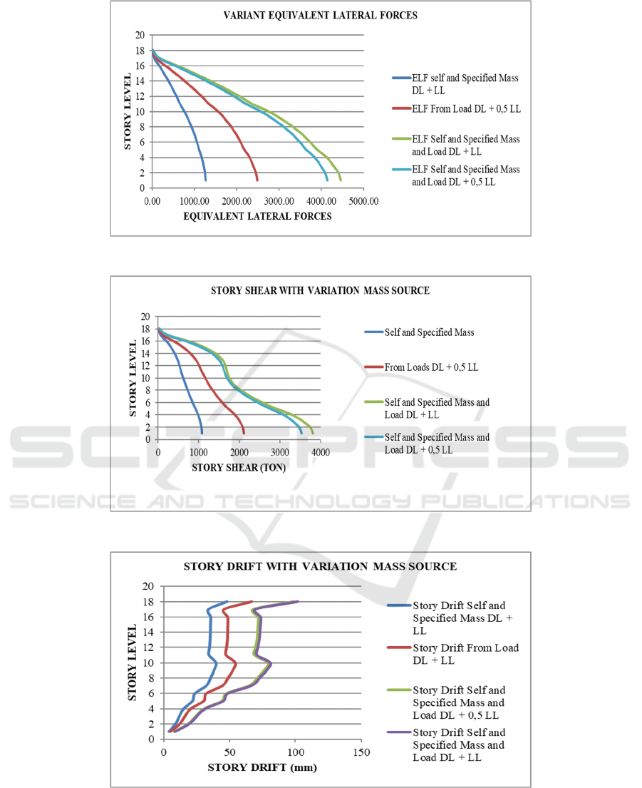
Figure 3: Variation ofequivalent lateral forces.
Figure 4: Story shear with variation mass source.
Figure 5: Story drift with variation mass source.
The Effect of Seismic Masses in Calculation of a 17 Multi-story Concrete Structure
187

Table 2: Time Period from Varian Masses.
Mode
1 2 3
Mass Source Condition
Self and Specified Mass
Default DL + LL
1.41
1
1.04
8
0.7
4
From Loads
DL + 0.5 LL
1.73
2
1.30
2
0.8
9
Self and Specified Mass and
Loads
DL + 0.5 LL
2.23
4
1.67
1.1
6
Self and Specified Mass and
Loads
DL + LL
2.29
8
1.72
1.1
9
Mass Source Manual
DL + LL
1.7
Figure 2 shows the mass sources. The mass is
calculated manually as a comparison. So, from the
value of ‘Self and specified’, the mass is 22.10%
lower. The value of ‘From load with DL + 0.5 LL’ is
2.75% bigger than the value of ‘Self and specified’
mass. The ‘load with DL + 0.5 LL’ is 72.43% and
the ‘Self and specified mass and load with DL + LL’
is 84.42%.
Figure 3 shows the Equivalent Lateral Load. The
mass is manually calculated as comparison. The value
of ‘From self and specified mass’ is 47.28% lower.
The value of ‘From load with DL + 0.5 LL’ is 2.11%
bigger. The value of ‘Self and specified mass and load
with DL + 0.5 LL’ is 71.57% and the value of ‘Self
and specified mass and load with DL + LL’ is
84.19%.
Figure 4 shows the story shear. Because the value
of ‘Mass manually calculated Dl + LL’ is near to the
value of ‘From load with DL + 0.5 LL’, so it is
assumed that the value of Story shear of ‘From load’
is the same as the comparison. And thus, the value of
‘From self and specified mass’ is 28,56 % lower. The
value of ‘Self and specified mass and load with DL +
0.5 LL’ is 64,16% and finally the value of ‘Self and
specified mass and load with DL + LL’ is 72,75%.
Figure 5 shows the story drift. Because the ‘Mass
calculated manual DL + LL’ is near to the ‘From load
with DL + 0.5 LL’, it is assumed that the value of
‘Story drift From load with DL + LL’ is the same as
the comparison. So, the value of ‘From self and
specified mass’ is 27,25% lower, then the value of
‘Self and specified mass and load with DL + 0.5 LL’
is 47,64%. And finally the value of ‘Self and specified
mass and load with DL + LL’ is 51,94%.
4 CONCLUSIONS
From the results of the analysis and discussion it is
concluded that:
1. The lowest time period is ‘From self’ and
‘specified mass’, after that ‘From load with DL
+0.5 LL’, next is the ‘Self and specified mass and
load with DL + 0.5 LL’, the last is ‘Self and
specified mass and load with DL + LL’. From
Table 2 can be seen that the period of ‘Mass
calculated manual DL + LL’ is near to ‘From load
with DL + 0.5 LL’.
2. Based on the Chosen Mass which is manually
calculated ‘DL + LL’ as the comparison, the value
of ‘From self and specified’ mass is 22.10%
lower, then the value of ‘From load with DL + 0.5
LL’ is bigger 2.75%, followed by the ‘Self and
specified mass and load with DL + 0.5 LL’ which
is 72.43 % and finally the value of ‘Self and
specified mass and load with DL + LL’, which is
84.42%.
3. If the Mass is manually calculated ‘DL + LL’ as a
comparison of the Equivalent Lateral Force, the
value of ‘From self and specified mass’ is 47.28%
lower, then the ‘From load with DL + 0.5 LL’,
which is 2.11% bigger/. Followed by the value of
‘Self and specified mass and load with DL + 0.5
LL’, which is 71.57% and finally the value of
‘Self and specified mass and load with DL + LL’
which is 84.19%.
4. Because the Mass which is manually calculated
‘DL + LL’ is near to the value of ‘From load with
DL + 0.5 LL’, it is assumed that the value of 'Story
shear of the From load is the same as the
comparison. The value of ‘Self and specified
mass’ is 28.56% lower, followed then by the value
of ‘Self and specified mass and load with DL +
0.5 LL’ which is 64.16% and finally the value of
‘Self and specified mass and load with DL + LL’,
which is 72.75%.
5. Because the Mass which is manually calculated
‘DL + LL’ is near to the value of ‘From load with
DL + 0.5 LL’, it is assumed that the value of Story
drift of ‘From load’ is the same and as the
comparison. The value of ‘Self and specified
mass’ is 27.25% lower, followed then by ‘Self and
specified mass and load with DL + 0.5 LL’, which
is 47.64 %, and finally the value of ‘Self and
specified mass and load with DL + LL’, which is
51.94%.
6. Since the model calculation of ‘Load with DL +
0.5 LL’ is near to Mass which is manually
calculated with ‘DL + LL’, it corresponds to the
recommendation of ASCE 7–10.
ICE-TES 2021 - International Conference on Emerging Issues in Technology, Engineering, and Science
188

REFERENCES
Akis, T. (2004). Lateral Load Analysis of Shear Wall -
Frame Structures. The Middle East Technical
University.
American Society of Civil Engineering. (2010). Minimum
Design Loads and Associated Criteria for Buildings
and Other Structures (ASCE 7–10). American Society
of Civil Engineering.
Atkins Structural Department. (2007). Manual For
Analysis & Design Using ETABS.
Badan Standardisasi Nasional. (2012). Tata cara
perencanaan ketahanan gempa untuk struktur
bangunan gedung dan non gedung (SNI 1726:2012).
Badan Standardisasi Nasional (BSN).
Budiono, B; Supriatna, L. (2011). Studi Komparasi Desain
Bangunan Tahan Gempa dengan Menggunakan SNI
03-1726-2002 dan RSNI 03-1726-201X. Penerbit ITB.
Computers and Structures Inc. (n.d.). CSI ETABS, Concrete
Shearwall Design Manual. University Avenue.
MacLeod, A. (1970). Shear Wall-Frame Interaction A
DESIGN AID.
Nageh, M. (2007). How to Model and Design High Rise
Building Using ETABS Program. Scientific Book
House For Publishing and Distributing.
Somers, P. (2012). Reinforced Concrete-Instructional
Materials Complementing FEMA P-751, Design
Examples. FEMA.
Wight, J. K. & MacGregor, J. G. (2012). Reinforced
Concrete: Mechanics and Design, 6th Edition. Pearson
Education, Inc.
Wiyono, R.D., Roi, C. M., & Lesmana. (2018). The Effect
of Shear Wall Configuration on Seismic Performance
in the Hotel Building. The 2nd International Joint
Conference on Advanced Engineering and Technology
(IJCAET 2017) and International Symposium on
Advanced Mechanical and Power Engineering
(ISAMPE 2017.
The Effect of Seismic Masses in Calculation of a 17 Multi-story Concrete Structure
189
