
Investigation on Performance of Solar Collector in the Adsorption
Process with Variation of Angle of Surface Plate
Hidayat
1a
, Sudarsono
2
, Rozaini Othman
3
, Mangkona
1
, Abdul Muis
1
,
Darma Aviva
1
and Abdul Halik
1
1
Department of Mechanical Engineering, Politeknik Negeri Samarinda, Jl. Ciptomangunkusumo, Samarinda, Indonesia
2
Department of Mechanical Engineering, Universitas Halu Oleo, Kampus Hijau, Kendari, Indonesia
3
Faculty of Mechanical Engineering, Universiti Teknologi MARA, Pematang Sauh, Malaysia
muis_64@yahoo.co.id, darmaaviva70@gmail.com, abdul.halik@polnes.ac.id
Keywords: Adsorbent, Solar Collector, Radiation Intensity, Charcoal Adsorbent, Temperature.
Abstract: Sunlight radiation energy is currently being used as an alternative energy source in order to replace energy
that is derived from petroleum fuel. Therefore the sun’s energy that never runs out can be utilized. This
research aims to determine the heat used by the collector for the desorption process and the angle variations
of the collector effect for collector efficiency using activated charcoal adsorbent. Accordingly that, one of
them can be used for the water cooling process using a solar collector device on a solar heat adsorption cycle
cooling machine. This research was conducted by varying the angle of the collector’s refrigeration with an
adsorption cycle using solar energy. The test results show that the average useful heat of the collector (Qu)
obtained by the 0° collector angle is 183.3 Watt, for 15° collector angle is 173.3 Watt, and for 30° collector
angle is 158,2 Watt. The average efficiency of the collector (η) obtained by the 0° collector angle is 48,22%,
15° collector angle is 45,322% and for 30° collector angle is 41,573%.
1 INTRODUCTION
Indonesia has substantial solar energy resources, with
an average solar radiation intensity of roughly 4.8
kWh/m
2
per day due to its equatorial location
between 6°N and 11°N and 9°E and 141°E. The total
annual solar radiation received by all regions of
Indonesia is around 2500 hours, with an average of
14.5 MJ/m
2
/day. Thus, unlimited solar energy may be
used to power the Indonesian people. Solar radiation
energy is currently used as an alternative energy
source to replace petroleum-based energy. One
application of radiation energy is water cooling via a
solar collector device on a solar heat adsorption cycle
cooling system.
Many researchers performing research to
investigate the performance of solar collectors. The
analysis was undertaken for a small public office
building in Bialystok (Poland), where solar collectors
were regarded as the primary source of renewable
energy for the domestic hot water (DHW) system,
with the idea that the existing oil boiler would serve
a
https://orcid.org/0000-0003-3672-1304
as a backup (Krawczyk, Żukowski, & Rodero, 2020).
The article discusses the viability of employing a non
concentrating direct absorption solar collector (DAC)
and compares its performance to that of a
conventional flat-plate collector (Tyagi, Phelan, &
Prasher, 2009). Experiments are conducted to
determine the influence of a CuO–water nanofluid as
the working fluid on a flat-plate solar collector
(Moghadam, Farzane-Gord, Sajadi, & Hoseyn-
Zadeh, 2014). Experiments were conducted to
determine the efficiency of a novel design and
production process for flat plate solar collectors.
Solar collector design adjustments are always a viable
option for improving thermal efficiency significantly
(Verma, Sharma, Gupta, Soni, & Upadhyay, 2020). a
novel technique for optimizing the performance of
solar thermal collectors The solar reflector is used in
conjunction with the solar collector to boost the
collector's reflectivity (Bhowmik & Amin, 2017).
research and optimization of the thermal performance
of an evacuated CPC (Compound Parabolic
Concentrator) solar collector equipped with a
Hidayat, ., Sudarsono, ., Othman, R., Mangkona, ., Muis, A., Aviva, D. and Halik, A.
Investigation on Performance of Solar Collector in the Adsorption Process with Variation of Angle of Surface Plate.
DOI: 10.5220/0010941100003260
In Proceedings of the 4th International Conference on Applied Science and Technology on Engineering Science (iCAST-ES 2021), pages 125-129
ISBN: 978-989-758-615-6; ISSN: 2975-8246
Copyright
c
2023 by SCITEPRESS – Science and Technology Publications, Lda. Under CC license (CC BY-NC-ND 4.0)
125
cylindrical absorber (Kim, Han, & Seo, 2008).
Artificial neural networks (ANNs), least squares
support vector machines (LSSVMs), and neuro-fuzzy
are utilized to advance prediction models for
photovoltaic-thermal solar collector (PV/T) thermal
performance (Ahmadi et al., 2020). a numerical
simulation of forced convective heat transfer using a
two-dimensional heat function formulation through a
direct absorption solar collector (DASC) packed with
water-copper nanofluid (Nasrin, Parvin, & Alim,
2015). Experiments have been done to ascertain the
collector's dual function. It is demonstrated that the
collector's thermal efficiency reached 50% when used
for water heating and fluctuated between 41% and
55% when used for air heating, depending on the
ambient temperature and flow velocity (Ma et al.,
2011). Dispersing nanometer-sized particles into the
base fluid is offered as an efficient way for improving
the working fluid's heat transfer capabilities (Amin,
Roghayeh, Fatemeh, & Fatollah, 2015).
As far as we know, no researcher carried out the
efficiency of the solar collector by varying the angle
of the surface to horizontal.
This research aims to ascertain the amount of heat
absorbed by the collector during the desorption
process and the angle variations in the collector's
effect on collector efficiency. The angle of the solar
collector’s surface was varied with the values 0
o
, 15
o
and 30
o
. The research was carried out by drying the
adsorber in the sun. The desorption process lasts ± 9
hours from 08.00 WIB - 17.00 WIB.
2 MATERIALS AND METHOD
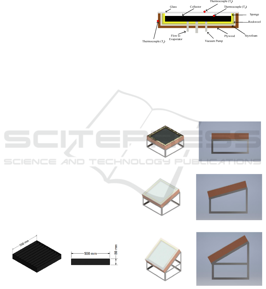
2.1 Dimension of Solar Collector
Figure 1 shows the three-dimensional model of the
solar collector. The dimension of the solar collector is
500 mm x 500 mm x 80 mm.
Figure 1: Three Dimensional Model of Solar Collector.
Figure 2 shows the inside part of the solar collector.
This part consists of glass, active charcoal, sponge,
Rockwool, plywood and styrofoam. Solar collectors
are a type of heat exchanger that generates heat
energy by employing solar radiation as the primary
energy source. When sunlight strikes the solar
collector's adsorber, some of the light is reflected
back into the environment. At the same time, the
majority is absorbed and converted to heat energy,
which is then transported to the solar collector's
circulating fluid for use in a variety of applications.
Figure 2: Inside Part of Solar Collector.
On solar collectors, three thermocouples are used
to determine the temperature of the glass surface, the
adsorbent plate surface, and the ambient temperature,
respectively. Before installing the thermocouple, it
should be checked at every point to make sure there
is no error in connection.
2.2 Material Properties
(a) Solar Collector with angle 0
o
(b) Solar Collector with angle 15
o
(c) Solar Collector with angle 30
o
Figure 3: Angle Variation of Solar Collector.
Figure 3 shows the angle variation of the solar
collector. The solar collector's angle is modified
iCAST-ES 2021 - International Conference on Applied Science and Technology on Engineering Science
126
utilizing three different angles, namely 0, 15 and 30.
Angle adjustments are included to demonstrate the
angle's effect on the intensity of sunlight striking the
collector. The intensity of the sunlight can be
calculated using the equation :
𝐺
=𝐺
×𝑐𝑜𝑠𝜃
(1)
where :
G
bT
: solar intensity on an inclined plane (W/m
2
)
G
bn
: solar radiation intensity at an angle of entrance
normal to the horizontal surface (W/m
2
)
θ
T
: the angle between the direction of the sun's rays and
the direction perpendicular to the inclined surface.
Calculation of heat absorbed at the collector can be
calculated using the formula :
𝑆=(𝜏𝛼)
×𝑄
×𝐴
(2)
where :
S : heat absorbed (J)
(τα) : the average absorptive transmissivity of glass
Q
it
: intensity of solar radiation (J/m
2
)
A
c
: collector cross-sectional area (m
2
)
Then, the heat loss coefficient lost to the collector can
be calculated using the formula:
𝑄𝐿 = 𝑄
×𝑄
×𝑄
(3)
where :
Q
T
: total heat loss at the top of the collector (W)
Q
B
: total heat loss at the bottom of the collector (W)
Q
E
: total heat loss on the sides of the collector (W)
Q
L
: total heat loss on each side of the collector (W)
The actual efficiency of the solar collector during the
test can be calculated in the empty state and contains
activated carbon. Empty collector efficiency can be
calculated using the following formula:
𝜂=
×
(4)
where :
η : collector efficiency (%)
Q
u
: heat absorbed by collector (W)
I
bn
: intensity of sunlight through the collector (W/m
2
)
A
c
: area of collector’s surface (m
2
)
3 RESULT AND DISCUSSION
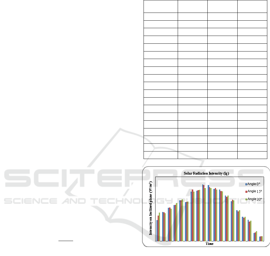
3.1 Calculation of Solar Radiation
Intensity
Table 1 shows the result calculation of solar radiation
intensity from 08:00 to 17:00. The maximum
intensity of solar radiation occurs around 12 o'clock
with the solar collector tilted at a 0-degree angle to
the horizon.
Table 1: The result calculation of solar radiation intensity.
Time
(WITA)
Angle 0° Angle 15° Angle 30°
08:00 259.94 319.63 353.74
08.30 361.56 358.71 349.16
09.00 413.22 416.16 426.35
09.30 448.29 451.53 475.96
10.00 505.46 506.41 517.54
10.30 483.69 488.89 493.63
11.00 614.52 638.60 632.74
11.30 625.73 633.84 651.98
12.00 703.34 698.76 691.79
12.30 697.89 672.02 689.83
13.00 649.63 663.38 647.75
13.30 641.09 621.48 638.69
14.00 568.48 551.86 584.76
14.30 494.56 514.00 507.05
15.00 384.92 370.63 400.06
15.30 299.75 290.80 313.36
16.00 263.74 243.18 253.85
16.30 103.23 111.37 124.14
17.00 54.41 60.65 58.44
Figure 4: Solar Radiation Intensity on an Inclined Plane.
Figure 4 shows the radiation intensity on an inclined
plane. It can be seen that the intensity of solar
radiation is almost the same and changes over time.
Overall, the highest global radiation intensity (Ig) lies
in the 0° collector angle test at 12.00, which is 703.34
W/m
2
. Meanwhile, the lowest global radiation
intensity (Ig) is in the 0° collector angle test at 17.00,
which is 54.41 W/m
2
. The average global radiation
intensity (Ig) from 08.00 – 17.00 WITA obtained by
collector angle 0° is 451.24 W/m
2
, collector angle 15°
453.259 W/m
2
, and collector angle 30° is 463.73
W/m
2
on each test day.
Investigation on Performance of Solar Collector in the Adsorption Process with Variation of Angle of Surface Plate
127

3.2 Calculation of the Heat Absorbed
by the Collector
Table 2: The results of the calculation of the heat absorbed
by the collector.
Time (WITA) Angle 0° Angle 15° Angle 30°
08:00 130,02 159,87 176,93
08.30 190,46 188,95 183,93
09.00 223,74 225,33 217,43
09.30 246,48 248,26 260,41
10.00 280,4 280,93 287,1
10.30 269,75 272,66 275,3
11.00 343,81 357,29 344,42
11.30 350,7 355,25 357,2
12.00 430,23 427,43 405,06
12.30 391,14 376,64 370,19
13.00 363,46 371,15 357,61
13.30 357,54 346,60 344,04
14.00 315,36 306,14 315,9
14.30 271,92 282,6 278,78
15.00 208,41 200,67 208,78
15.30 157,9 153,18 159,48
16.00 131,92 121,64 126,97
16.30 46,56 50,23 55,99
17.00 19,63 21,89 21,09
The relationship between the heat absorbed by the
collector and time can be seen from Figure 5 below:
Figure 5: Heat absorbed by Collector.
It can be seen that the heat absorbed by the collector
(S) is almost the same and changes over time
according to the angle of each collector. Similar to the
intensity of solar radiation (G
bT
), the heat absorbed by
the collector (S) can also be affected by erratic
weather factors, wind speed and the angle of
incidence of light on the collector surface (θ
1
).
Overall, the highest heat absorbed by the collector (S)
lies in the 0° collector angle test at 12.00 which is
430,23 Watt. Meanwhile, the lowest heat absorbed by
the collector (S) lies in the 0° collector angle test at
17.00, which is 19,63 Watt. The average heat
absorbed by the collector (S) obtained by the 0° angle
collector is 248,916 Watt, the 15° collector angle is
249,826 Watt, and the 30° angle collector is 249,821
Watt on each test day.
3.3 Calculation of the Collector
Efficiency
Figure 6: Efficiency of Solar Collector.
It can be seen that the efficiency (η) tends to be almost
the same. In general, collector efficiency is the ratio
between useful heat and the intensity of solar
radiation entering the absorber. The useful heat from
the collector is the heat flux absorbed by the absorber
minus the rate of heat loss to the environment. The
amount of useful calorific value does not necessarily
cause the value of useful efficiency to be large. The
useful calorific value is obtained from the difference
between the heat absorbed by the collector and the
heat loss lost to the collector. The greater the heat
absorbed by the collector, the greater the heat loss lost
to the collector to the environment.
Similar to the discussion of the useful heat graph
(Qu), in this measurement at 16.30 the calculation of
efficiency (η) began to get a negative value. This
happens as described because at the time of the test
the heat loss lost to the collector (Ql) is greater than
the heat absorbed by the collector (S). The peak of
heat absorbed by the collector occurred at 12.00, after
which the heat absorbed began to decline. While the
heat loss lost from the collector decreases according
to the measurement of the heat temperature that has
been obtained. Therefore, to get the average
efficiency (η) that is effective, it is taken from 08.00
to 16.00 . Overall the highest efficiency (η) lies in
testing the 0° angle collector obtaining a value of
48,22 %, the 15° angle at 45,32 % and the 30° angle
collector getting a value of 41,57 %.
Heat Absorbed by Collector (W)
Time (WITA)
Heat Absorbed (S) by Time
Sudut 0°
Sudut 15°
Sudut 30°
Efficiency (%)
Time (WITA)
Efficiency (η) by time
Sudut 0°
Sudut 15°
Sudut 30°
iCAST-ES 2021 - International Conference on Applied Science and Technology on Engineering Science
128

3.4 Discussion
The researcher suggests that this can be accomplished
by adding an angle regulator to the collector that
allows it to be adjusted in response to the angle of
incidence of the sun and variations in other adsorbent
materials, as well as by selecting a good insulating
material to minimize heat loss to the collector.
4 CONCLUSIONS
From the results of tests and analyzes that have been
carried out, conclusions can be drawn from this
research, namely as follows:
1). The highest useful heat in the collector (Qu) lies
in testing the collector at an angle of 0° at 12.00
which is 272.064 Watt. Meanwhile, the lowest
useful heat in the collector (Qu) lies in the
collector test at an angle of 0° at 17.00, which is
-42.18 Watt. The average proper heat at the
collector (Qu) obtained by the 0° angle collector
is 139.878 Watt, the 15° collector angle is
118.624 Watt, and the 30° angle collector is
113.611 Watt on each test day.
2). Collector efficiency (η) from 08.00–16.00
WITA. The 0° angle collector gets a value of
42.617%, the 15° angle is 36.377% and the 30°
angle collector gets a value of 33.708%.
REFERENCES
Ahmadi, M. H., Baghban, A., Sadeghzadeh, M., Zamen,
M., Mosavi, A., Shamshirband, S., … Mohammadi-
Khanaposhtani, M. (2020). Evaluation of electrical
efficiency of photovoltaic thermal solar collector.
Engineering Applications of Computational Fluid
Mechanics, 14(1), 545–565. https://doi.org/10.1080
/19942060.2020.1734094
Amin, T. E., Roghayeh, G., Fatemeh, R., & Fatollah, P.
(2015). Evaluation of Nanoparticle Shape Effect on a
Nanofluid Based Flat-Plate Solar Collector Efficiency.
Energy Exploration & Exploitation, 33(5), 659–676.
https://doi.org/10.1260/0144-5987.33.5.659
Bhowmik, H., & Amin, R. (2017). Efficiency improvement
of flat plate solar collector using reflector. Energy
Reports, 3, 119–123. https://doi.org/10.1016/j.egyr.2
017.08.002
Kim, Y., Han, G., & Seo, T. (2008). An evaluation on
thermal performance of CPC solar collector.
International Communications in Heat and Mass
Transfer, 35(4), 446–457. https://doi.org/10.
1016/j.icheatmasstransfer.2007.09.007
Krawczyk, D. A., Żukowski, M., & Rodero, A. (2020).
Efficiency of a solar collector system for the public
building depending on its location. Environmental
Science and Pollution Research, 27(1), 101–110.
https://doi.org/10.1007/s11356-019-05077-2
Ma, J., Sun, W., Ji, J., Zhang, Y., Zhang, A., & Fan, W.
(2011). Experimental and theoretical study of the
efficiency of a dual-function solar collector. Applied
Thermal Engineering, 31(10), 1751–1756.
https://doi.org/10.1016/j.applthermaleng.2011.02.019
Moghadam, A. J., Farzane-Gord, M., Sajadi, M., &
Hoseyn-Zadeh, M. (2014). Effects of CuO/water
nanofluid on the efficiency of a flat-plate solar
collector. Experimental Thermal and Fluid Science, 58,
9–14. https://doi.org/10.1016/j.expthermflusci.2014.
06.014
Nasrin, R., Parvin, S., & Alim, M. A. (2015). Heat Transfer
and Collector Efficiency through a Direct Absorption
Solar Collector with Radiative Heat Flux Effect.
Numerical Heat Transfer, Part A: Applications, 68(8), 88
7–907. https://doi.org/10.1080/10407782.2015.1023122
Tyagi, H., Phelan, P., & Prasher, R. (2009). Predicted
Efficiency of a Low-Temperature Nanofluid-Based
Direct Absorption Solar Collector. Journal of Solar
Energy Engineering, 131(4). https://doi.org/10.1115/1
.3197562
Verma, S. K., Sharma, K., Gupta, N. K., Soni, P., &
Upadhyay, N. (2020). “Performance comparison of
innovative spiral shaped solar collector design with
conventional flat plate solar collector.” Energy, 194,
116853. https://doi.org/https://doi.org/10.1016/j.energ
y.2019.116853
Investigation on Performance of Solar Collector in the Adsorption Process with Variation of Angle of Surface Plate
129
