
Simulation of Water Supply Pump System with
PLC based Control
Sudirman
a
, I Nyoman Gede Baliarta
b
, Putu Darmawa
c
and D. G. Agustriputra
d
Mechanical Department, Bali State Polytechnic, Jl. Kampus Bukit Jimbaran, Badung-Bali, Indonesia
Keywords: Smart Relay, Input, Output, Ladder Diagram.
Abstract: This paper discusses the simulation of the control of a clean water pump system for supply to the building.
There are several systems in the field, generally using conventional controls. The system uses a contactor and
WLC. The simulation system is made with 3 tanks, namely tower tank, consumption tank and ground tank.
This simulation control system using PLC control. The PLC used is the Zelio SR3PACKBD Smart Relay.
The inputs are stainless steel rod sensors in the tower tank and ground tank. The outputs are 2 pump motors
and a solenoid valve. The PLC program used is Ladder diagram with ZELIO SOFT 2 program. Pumps 1 and
2 will operate from low level to middle level. When middle level to high level only pump 1 operates.
Meanwhile, when the hight level there is no pump operating. The test results show satisfactory results
according to the program made, and the equipment required is very simple compared to conventional controls.
1 INTRODUCTION
The main objective in designing a water supply
system for high-rise buildings is to ensure adequate
water supply at all times, both in terms of required
pressure and discharge for all outlets, fixtures and
equipment. In addition, also to achieve energy saving,
efficient and energy saving. (Rodrigues,
Fernanda.2011).
Bali as a foreign and domestic tourist destination,
must provide adequate accommodation to ensure the
comfort of International and Domestic guests, during
their stay in Bali. Hotels and villas grow moldy
anticipating the arrival of guests. Hotel and Villa
building facilities adjust the status of the Hotel and
Villa. The basic facilities for hotels and villas are the
availability of clean water whenever needed.
Disruption of the clean water supply system in a
hotel will also disrupt the comfort of the guests
staying and will reduce the credibility of the hotel,
which in turn will reduce the hotel occupancy rate.
For this reason, a reliable clean water supply system
is needed to meet the basic needs of guests, so that the
hotel's credibility is maintained.
a
https://orcid.org/0000-0003-2816-523X
b
https://orcid.org/0000-0003-3286-2732
c
https://orcid.org/0000-0001-7621-6420
d
https://orcid.org/0000-0002-9422-7876
There are many clean supply pump systems
installed in hotels depending on the hotel owner's
request. The supply system uses a tower tank and
distribution by gravity and the supply system uses a
ground tank and distribution uses a pump. Each
system has its advantages and disadvantages. ( Pears,
A., 2002).
Building utilities consist of mechanical and
electrical systems. One of the sub-mechanical
systems is a clean water supply system. Clean water
supply systems installed in hotels mostly use 2 or 3
supply pumps. For hotel or villa locations with flat
locations, most pumps supply directly to the end-user
by using pressure as the on-off control of the pump.
Meanwhile, hotels/villas with high-rise locations use
tower tanks for water distribution to end-users.
(Vinita Chanan, 2013).
The Clean Water Distribution System in Multi-
story Buildings by Wujek, Joseph B. (2012) is
divided into several systems, namely:
Sudirman, ., Nyoman Gede Baliarta, I., Darmawa, P. and Agustriputra, D.
Simulation of Water Supply Pump System with PLC based Control.
DOI: 10.5220/0010947800003260
In Proceedings of the 4th International Conference on Applied Science and Technology on Engineering Science (iCAST-ES 2021), pages 477-483
ISBN: 978-989-758-615-6; ISSN: 2975-8246
Copyright
c
2023 by SCITEPRESS – Science and Technology Publications, Lda. Under CC license (CC BY-NC-ND 4.0)
477

1.1 Up-feed System
In this system, the distribution pipe directly from the
ground tank with the pump is directly connected to
the main pipe for providing clean water to the
building, in this case using the full capacity of the
pump. Due to the limited pressure in the pipe and the
limited size of the branch pipe from the main pipe,
this system is especially applicable for housing and
small low-rise buildings (Alfred, 1984). The
manufacture is relatively cheap but the pump breaks
quickly.
Figure 1: Up Feed System.
The disadvantages of this system are:
a. pump working continuously
b. The height is limited because the strength of
the pipe is limited to anticipate the pressure
of the water inside.
1.2 Down Feed System
In this system, water is first stored in the ground tank,
then pumped to the upper tank which is usually
installed on the roof or on the highest floor of the
building. From here the water is distributed
throughout the building. This roof tank system is
quite efficient to implement because:
a. As long as the water is used, the pressure
changes that occur in the plumbing tool are
insignificant.
b. The pump system that raises water to the top
tank works automatically in a very simple
way so that difficulties can be suppressed.
c. Tank maintenance is very simple compared
to for example a pressure tank.
The advantages of this down feed system are:
a. The pump does not work continuously so it
is more efficient and durable.
b. Clean water is always available at all times.
c. No need for automatic pump.
The disadvantages of this system are :
a. Requires additional costs for the
procurement of additional tanks.
b. Adding weight to the structure of the
building.
c. Increase maintenance costs.
For long-term use, this system is effective and
efficient even though it is expensive to manufacture.
If the number of floors is very large, the water
pressure in the pila is very high, so that the pipe can
burst due to high pressure (every seven meters of
pressure the pipe receives a pressure of 1
atmosphere), then this down feed system is equipped
with: Spillback Tank
Figure 2: Down Feed System.
1.3 Spillback Tank
In the form of auxiliary tanks that are placed on each
particular floor. Each tank is equipped with a pressure
control valve. When the water pressure is high, the
valve will close. The most important thing in this roof
tank system is to determine the location of the tank
whether it is installed in the ceiling, on the roof, or
installed in a special tower. This determination must
be based on the type of plumbing device installed on
the highest floor of the building and which determines
the highest working pressure.
Figure 3: Down Feed System With Spill Back Tank.
The working principle of this system is as follows:
a. Water that has been pumped in a spill back
tank that is on several floors so that the air
inside is compressed.
iCAST-ES 2021 - International Conference on Applied Science and Technology on Engineering Science
478

b. The water in the tank flows through the
building's distribution system. The pump is
regulated automatically by a relative that
drives the electric motor switch that drives
the pump.
c. The pump stops working when the tank
pressure has reached the maximum set limit
and works again after the tank pressure
reaches a predetermined minimum limit as
well. This area of pressure fluctuation is
usually set between 1.0 -1.5 kg/cm'.
1.4 Presure Reducer Valve (PRV,
Katup Reduksi Tekanan)
On a relatively large number of floors, there is a
possibility that the pressure in the pipe is very high so
it needs to be reduced with a valve. These valves are
placed on certain floors.
Figure 4: Down Feed System With Pressure Reducer Valve.
1.5 Some Systems Applied in Hotels
Surveys to hotels that have been carried out to find
out directly the installation of clean water supply
systems in hotels with regard to this research, namely:
1.5.1 Double-Six.Luxury Hotel Seminyak
The installation of a clean supply system at Double-
Six.Luxury Hotel Seminyak uses 3 pumps. The three
pumps are alternately controlled by the Control Panel.
This installation is without tower tank. From the
pump, water is distributed directly to the user at a
pressure of 3.5 Bar, using a Digital Pressure
Transmitter.
Figure 5: The installation of a clean supply system at
Double-Six.Luxury Hotel Seminyak uses 3 pumps.
Figure 6: Control Panel of the clean water supply system at
Double-Six Luxury Hotel Seminyak.
1.5.2 Estate Villa Four Seasons Resort
Jimbaran
Figure 7: Plumbing installation and control panel of clean
water supply system Estate Villa Four Seasons Resort
Jimbaran.
The clean water supply system at Estate Villa Four
Seasons Resort Jimbaran uses 2 pumps. Switch on
duty pump from pump 1 to pump 2 using a switch
over relay. Water is distributed directly to the end-
user of the pump using a pressure switch for on-off.
1.5.3 Luna 2 Hotel Seminyak
Clean water is pumped from the ground tank to the
tower tank, the pump turns on and off based on the
flow to the end user by gravity. On and off the supply
pump to the tower using WLC based on the water
level in the tower tank
Simulation of Water Supply Pump System with PLC based Control
479
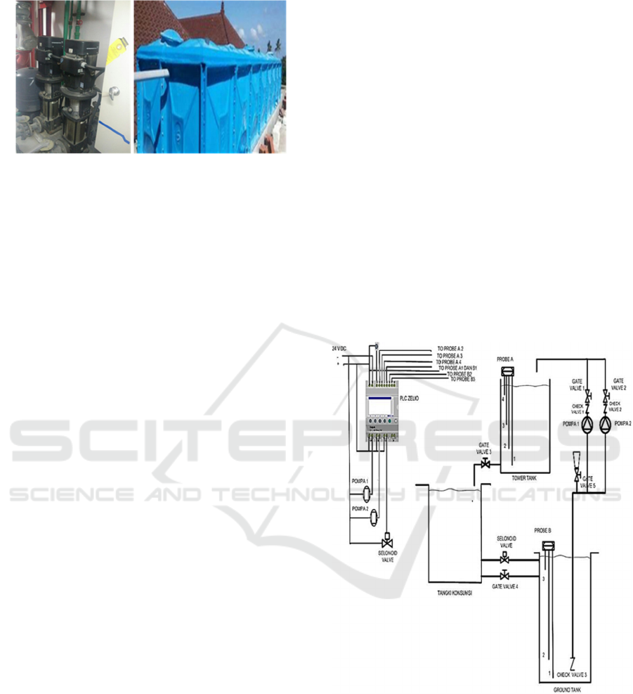
Figure 8: Installation of a clean water supply system and
tower tank at Luna 2 Hotel Seminyak.
Pump control that has been widely applied now is
using PLC, as done by Indra Saputra et al, (2013).
They designed the Water Level Control using an
Omron Sysmac C200H PLC equipped with
Wonderware InTouch 10.5 SCADA Software.
Dendin Supriadi, (2015), made a water level control
system using an ultrasonic sensor based on PLC
(Programmable Logic Controller). For monitoring
and control interfaces on this system, the Omron
NB7W-TW00B HMI is used, so that all events that
occur in the system can be directly controlled and
monitored. in real time. This water level control
system has two controls, namely automatic control
and manual control.
Sri Kusumastuti and Suryono (2015), made a
practical teaching aid for water level control in
reservoirs and tanks using PLC. With an output in the
form of a water pump and a solenoid valve.
Gebremaryam Alem and Dr. Krishnanaik Vankdoth
(2016), designed a water level control using PLC.
With input in the form of electronic sensors in the
form of limit switches and outputs in the form of
pump motors and solenoid valves, and they create
Ladder logic diagram programs using the Softcomfort
Logo.
Paper written by Cosmina Illes et al, (2017), about
water level control system using PLC and wireless
sensors. The aim of the paper is to present the
cheapest cost method for water level control using
wireless.
For this water level control simulation project,
the Schneider Smart Relay Zelio Logic
SR3PACKBD PLC is used.
2 METHODOLOGY
The scheme built in the clean water system simulation
project with PLC is as shown in Figure 8 below.
This Simulation Scheme consists of 3 tanks,
namely;
1. Tower Tank as a water reservoir whose position
is the highest, or its position on the roof of the
building. The tower tank is equipped with probe
A (water level sensor) with 4 sensor rods.
a. Sensor No. Probe A1 as cummon
b. Sensor No. Probe A2 as low level sensor
c. Sensor No. A3 probe as medium level sensor
d. Sensor No. A4 probe as a hight level sensor
2. Consumption Tank is a tank which is a water
storage tank that comes out of the Tower Tank
which is associated as a water consumer in a
building. The consumption tank is connected to
the ground tank by 2 different pipes. The first
pipe is equipped with a solenoid valve, the way
it works is when the ground tank is in a low level
position, the solenoid valve will automatically
open. The second pipe is equipped with a gate
valve 4, which works manually.
Figure 9: Simulation scheme of clean water pump control
using PLC.
3. Ground Tank is a storage tank whose position is
at the bottom of a building. Water reservoirs
from drinking water companies or underground
water reservoirs. The end of the pipe that enters
the ground tank is the pump suction pipe, check
valve 3 is installed whose function is so that the
pump suction pipe always has water. Ground
iCAST-ES 2021 - International Conference on Applied Science and Technology on Engineering Science
480

tank is equipped with probe B. Which consists of
3 sensor rods,
a. Sensor No. Probe B1 is as cummon
b. Sensor No. Probe B2 as Low level sensor
c. Sensor No. Probe B3 as a hight level sensor.
2.1 Description Sistem
This simulation tool uses 2 pumps, which move water
from the Ground tank to the Tower tank, when the
water is consumed (gate valve 3 is manually opened),
the water is accommodated by the consumption tank.
The consumption tank collects water from the tower
tank and forwards it to the ground tank again. Thus
the water cycle in this simulation tool. Sistem kontrol
akan bekerja jika kondisi level air pada Ground tank
tidak mencapai posisi Low Level (batang Probe B2
tidak menyentuh air) dan kondisi level air di Tower
tank tidak hight level (batang Probe A4 tidak
menyentuh air).
When the Probe B3 ground tank sensor is
submerged in water and Probe A2 is not touched by
the water in the tower tank, Pump 1 and Pump 2 will
turn on pumping the ground tank water to the tower
tank, When the tower tank water level touches the
Probe A3 sensor, pump 2 will turn off and only pump
1 is still alive. When the water level reaches/touches
probe B4 (hight level), pump 1 will also stop.
When gate valve 3 is opened, water flows to fill
the consumption tank. When the water level of the
tower tank decreases and the probe rod A3 does not
touch the water, pump 2 will automatically start
pumping water from the ground tank to fill the tower
tank. When the water consumption is too much, the
tower tank water level continues to decrease and the
water level does not touch the A2 sensor probe, then
pump 1 will run and fill the tower tank.
If the pump is running continuously, and the
condition of the water level in the ground tank
continues to drop until the ground tank water level
does not touch the probe rod B2, then the system will
not work. Because if it is continued, the pump will
work in dry running condition (no water is pumped).
This can cause the pump to fail and this system is
designed to save the pump from being severely
damaged.
In this condition, the solenoid valve will
automatically open, filling water from the
consumption tank, the water flows by gravity.
2.2 Program PLC (Ladder Diagram
Program)
This PLC program is in the form of a Ladder Diagram
Program that will be uploaded/transferred to the PLC.
PLC used is PLC SMART RELAY ZELIO
SR3PACKBD. While the software used is ZELIO
SOFT 2. PLC and its software is a product of
SCHNEIDER.
For PLC programs there are inputs and outputs. The
inputs of the PLC are;
a. Input 1 is the start of the program in the
form of a push button
b. Input 2 is the sensor Probe A2 (low level
tower tank)
c. Input 3 is sensor probe A3 (medium level
tower tank)
d. Input 4 is the sensor probe A4 (hight level
tower tank)
e. Input 5 is sensor probe B2 (low level
ground tank)
f. Input 6 is sensor probe B3 (high level
ground tank).
The output of the PLC is;
a. Output 1 is Pump 1
b. Output 2 is Pump 2
c. Output 3 is the Selenoid Valve.
The Ladder Diagram Program that is made in
accordance with the work system as described above
is as shown in Figure 10.
3 RESULT
Ladder Diagram program created using Zelio Soft 2
program, then uploaded to the Smart Realy PLC using
an SR2USB01 USB cable that is compatible with
Windows 7, 8.1 or 10.
Simulation of Water Supply Pump System with PLC based Control
481

Figure 10: Ladder Diagram Program.
Figure 11: Schneider SR3PACKBD PLC and USB cable
SR2USB01.
After the Ladder diagram is uploaded to the PLC, the
results of the running test simulation of the water
supply control system with the PLC are as follows,
which are shown in Table 1.
Table 1: Matrik Kerja Water Supplay Pump System.
No
Kondisi Level
air
On Duty
Pompa 1 Pompa 2
Selenoid
Valve
1
Hight Level
Tower Tank
OFF OFF OFF
2
Medium Level
Tower Tank
ON OFF OFF
3
Low Level
Tower Tank
ON ON OFF
4
Hight Level
Ground Tank
ON ON OFF
5
Low Level
Ground Tank
OFF OFF ON
Table 1 is the output condition with several input
conditions in the form of the water level in the ground
tank and tower tank.
Pump 1 will work when the tower tank is in low,
medium level and high level ground conditions.
Pump 2 works when the tower tank is in a low level
condition and the ground tank is in a high level
condition.
The solenoid valve will work or open if the
ground tank is in a low level condition, which will
drain water from the consumption tank to the ground
tank.
Figure 12: Simulation of Water Supply Pump System.
4 CONCLUSIONS
The PLC-based Water supply control simulation
system that was made showed very satisfactory
results. The big advantage of PLC based water supply
iCAST-ES 2021 - International Conference on Applied Science and Technology on Engineering Science
482

control is that it has maximum accuracy, also has
higher reliability and small space requirements
compared to conventional controls.
ACKNOWLEDGEMENTS
Our gratitude goes to P3M a Bali State Polytechnic
who has funded this research through DIPA 2021
funds.
REFERENCES
Alfred ,2003, High-Rise Domestic Water Systems,
Advanced Plumbing Technology,: Construction
Industry Press, Elmhurst, IL
Cosmina Illes, Gabriel Nicolae Popa and Ioan Filip, 2014,
Water level control system using PLC and wireless
sensors, reseach gate.net /publication/261381165.
Dendin Supriadi, 2015, Rancang Bangun Sistem
Pengendalian Ketinggian Air Menggunakan Sensor
Ultrasonic Berbasis Plc (Programmable Logic
Controller), TEDC Vol.9 No.3 September 2015: 192-
196.
Fernanda Rodrigues, Romeu Vicente, Armando Silva
Afonso, Maria João Sá, 2011, The contribution of the
water supply and drainage installations for the
sustainability of an academic building, Proceedings of
37th International Symposium CIB W062 on Water
Supply and Drainage for Buildings, 25 – 28th
September 2011 - Aveiro, Portugal
Gebremaryam Alem, Krishnanaik Vankdoth, 2016,
Automatic Fluid Level Control Using Programmable
Logic Controller, International Research Journal of
Engineering and Technology (IRJET), Volume: 03
Issue: 07 | July-2016.
Indra Saputra, Lukmanul Hakim, Sri Ratna S, 2013,
Perancangan Water Level Control Menggunakan PLC
Omron Sysmac C200H Yang Dilengkapi Software
SCADA Wonderware InTouch 10.5, Volume 7, No. 1,
Januari 2013, ELECTRICIAN – Jurnal Rekayasa dan
Teknologi Elektro.
Muhammad Teguh Ardiyanto dan Agung Prijo Budijono,
2013, Rancang Bangun Tarainer Kontrol Level Air,
JRM.Volume 01 Nomor 01 Tahun 2013, 80-84.
Pears, A. 2002 The 60L Green Building – How does it
minimise mains water consumption?. Seminar
Proceedings Redesigning the Urban Water Cycle,
Institute for Sustainable Futures, Washington, D.C.
Silva Afonso, 2007, Safe Water Supply In Buildings. The
Importance Of Risk Prevention, Water Supply and
Drainage for Buildings September 19-21, 2007/. 33rd
International Symposium, Brno, Czech Republic
Sri Kusumastuti dan Suryono, 2015, Rancang Bangun
Peraga Praktikum Kontrol Level Air Pada Tandon Dan
Bak Menggunakan PLC, ORBITH VOL. 11 NO. 1
MARET 2015 : 9 – 13.
Wujek, Josep B. 2010, Mechanical and electrical systems
in architecture, engineering, and construction 5th ed.
New Jersey.
Vinita Chaan, 2013, Sustainable Water Management in
Commercial Office Buildings, Innovations in Water:
Ozwater Convention & Exhibition, 6-10 April 20013,
Perth.
Simulation of Water Supply Pump System with PLC based Control
483
