
A Simple Speed and Torque Meter using Arduino
Made Purbhawa, Kadek Amerta Yasa, Ketut Gede Sudiartha, Wayan Jondra
and Igna Dwijaya Saputra
a
Department of Electrical Engineering, Politeknik Negeri Bali, Jl Bukit Jimbaran, Badung, Bali, Indonesia
Keywords: Torque Meter, Speed Meter, Arduino.
Abstract: Speed and torque are crucial aspects of the operation of an electric motor. The general method to measure the
speed and torque is using a speed meter and torque meter. Unfortunately, these instruments are pricy in the
market. It is also difficult to fix those instruments because they fail in operation due to hardware problems. In
this paper, a simple device for measuring speed and torque, voltage, and current are built using an Arduino as
a central processor. This device also has a display and has a connection to a computer for storing data and
displaying these data in LabVIEW. The test results for these instruments show the average error both for
speed meter and torque meter were 0.11% and 0.81% consecutively.
1 INTRODUCTION
Induction motors are widely used in society, both in
industry and for household appliances. This motor is
cheap and easy to operate, so it is excellent as
electrical equipment. In its operation, it is necessary
to know the extent of the speed and the torque
produced as part of a study of the characteristics of
induction motors. Students must understand the
rotational speed during operation and the value of
torque generated, both at no and under load. This
torque can be controlled or reduced ripple (Alsofyani
and Idris, 2016), (Ma,2021), (Wang, 2020), (Sharma
and Pal, 019). It is usually done in the laboratory of
electrical machines using a torque meter to measure
torque and a tachometer to measure motor speed. In
general, measurement is also carried out using analog
measuring instruments as modules according to
suitable learning materials.
Nevertheless, this measuring tool is costly which
can reach tens of millions of rupiah. Experience in the
field, especially at the Electrical Machinery
Laboratory, found that the measuring instruments
used by students in carrying out practicals are easily
damaged. A good quality measuring instrument also
fails to operate due to a large number of people using
this instrument. The replacement takes a long time
because it is an imported product and must be ordered
at a high price from a distributor. For this reason, it is
a
https://orcid.org/0000-0002-1267-6222
necessary to build a torque and speed measuring
instrument that is cheap, reliable, and can be replaced
quickly in case of damage.
2 PROPOSED METHOD
This research has been conducted at the electrical
machinery laboratory, Department of Electrical
Engineering, Bali State Polytechnic. The initial
survey was conducted to determine how the
measurements were previously carried out, the
number of repetitive measures, and the tools. The
next step is to design a measuring instrument using
the Arduino microcontroller and its supporting
components. Furthermore, the finished device is
tested by comparing the measurement results with
standard tools owned by the Department of Electrical
Engineering. The stages of this research are drawn as
a figure that can be seen in Figure 1.
The next step is to build a system that can record
data (data logger) to a computer. This operation can
be performed using the LabVIEW software. From the
results of this data recording, the data can be plotted,
and also the necessary calculations are carried out,
such as to find power losses.
The whole system, both measuring instruments
that
use
a
microcontroller
and
programs
that
have
710
Purbhawa, M., Yasa, K., Sudiartha, K., Jondra, W. and Saputra, I.
A Simple Speed and Torque Meter using Arduino.
DOI: 10.5220/0010951900003260
In Proceedings of the 4th International Conference on Applied Science and Technology on Engineering Science (iCAST-ES 2021), pages 710-715
ISBN: 978-989-758-615-6; ISSN: 2975-8246
Copyright
c
2023 by SCITEPRESS – Science and Technology Publications, Lda. Under CC license (CC BY-NC-ND 4.0)
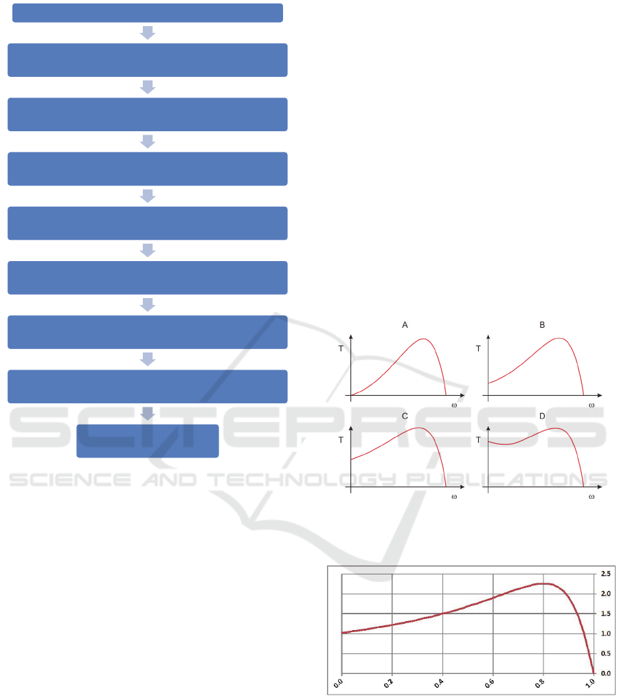
Figure 1: Research Stages.
been built using LabVIEW, will be tested to find the
specifications of the tools.
Speed and Torque
a. Speed
The synchronous speed of an AC motor, ns is the
rotational rate of the stator magnetic field with the
equation:
s = (n
s
– n
r
) / n
s
(1)
where f is the frequency of the power supply, p is
the number of magnetic poles, and with ns as a
synchronous speed of the machine with units for f in
Hertz and ns in RPM, the formula becomes (
Steinmetz,
1997) and (Alger, 1949):
n
s
= 2f/p.((60 s/min) = 120f/p. (s/min)
(2)
b. Slip
Typical curve of the torque as a function of slip
represented as "g" here. Slip, s, is defined as the
difference between synchronous speed and operating
speed, at the same frequency, expressed in rpm, or
percentage or ratio of synchronous speed. So:
s = (n
s
– n
r
) / n
s
(3)
Where ns is the electric speed of the stator, nr is
the mechanical speed of the rotor (NSW HSC, 2012)
(NEMA MG-1 2007, 2008). The value of the slip is
varied, which varies from zero at synchronous speed
and 1 when the rotor is jammed determines motor
torque. For some reason, the short-circuited rotor
windings have negligible resistance. Even a tiny slip
induces large currents in the rotor and produces
significant torque (Penton Media, 2007). When the
load reaches the highest value, the slip of small
motors varies from more than 5%, while it has only
less than 1% for large engines (Motor Formula,
1999). This speed variation can cause load sharing
problems when motors of different sizes are
mechanically connected.
c. Standard Torque
The speed-torque curves for the four types of
induction motors can be seen in Figure 2.
Figure 2: Velocity Curve - Torque A) Single phase, B)
Polyphase cage, C) Polyphase cage deep bar, D) Polyphase
double cage.
Figure 3: A typical speed-torque curve for a NEMA Design
B Motor.
Figure 3 shows the curve of the typical speed-
torque relationship of a standard NEMA Design B
polyphase induction motor. Suitable for most low-
performance loads such as pumps and centrifugal
fans, The following typical torque range limits design
B motors (Avinash and Ravi, 2013).
Start
Surveymethodandmeasurement
configuration
Designingmeasuringinstrumentsusinga
microcontroller
Makingmeasuringtools
Microcontrollermeasuringinstrument
testing
Buildasystemtoreadmeasurementresults
withLabVIEW
OverallToolTesting
Testresultsintheformoftool
specifications
end
A Simple Speed and Torque Meter using Arduino
711

Breakdown torque (peak torque),
175-300% of rated torque
Rotor-locked torque (torque at 100% slip),
75-275% of rated torque
Pull-up torque,
65-190% of rated torque.
In the normal load range of the motor, the torque
slope is approximately linear or proportional to the
slip because the value of the rotor resistance divided
by the slip, R'r/s, dominates the torque linearly
(NEMA Standard, 2007). If the load increases above
the rated load, the rotor and rotor leakage reactance
factor gradually become more significant to R'r/s. The
torque gradually curves towards breakdown torque.
When the load torque increases beyond the
breakdown torque, the motor stops.
Locked rotor torque or drive torque is the torque
developed by an electric motor when it starts at zero
speed.
High starting torque is highly used for
applications or difficult-to-start machines, such as
positive displacement pumps or cranes. Lower
starting torque is acceptable for centrifugal fans or
pumps where the starting load is low or near zero.
Pull-up Torque
Pull-up torque can be described as the minimum
torque value developed by an electric motor when
running from zero to full load speed (before reaching
the breakdown torque point). When the engine starts
and starts to accelerate, the pull-up torque value is
decreased at a certain speed to a low point. The torque
breakdown point increases its value to the highest
torque at a higher speed. The pull-up torque may be
necessary for applications that require power to pass
through some temporary barrier to reach working
conditions.
Breakdown Torque
Breakdown torque is the highest torque available
before torque is reduced as the machine accelerates to
a working state.
Full Load Torque or Brake Torque
Full Load Torque is the torque required to produce
the rated power of the electric motor at full load
speed. In imperial units, Full Load Torque can be
expressed as
T = 5252 Php/nr
(4)
where:
T = full load torque (lb ft)
Php = rated horsepower
nr = rated rotation speed (rev/min, rpm)
The rated torque in metric units, can be denoted as:
T = 9550 PkW/nr
where:
T = rated torque (Nm)
PkW = rated power (kW)
nr = rated rotational speed (rpm)
Torque measurement can be carried out in various
ways and techniques, including using a rheometer on
a permanent magnet motor (Letner et al., 2019), using
a method based on an encoder (Liu et al., 2014), and
based on Electromotive Force for Surface-Mounted
permanent magnet motors (
Simón-Sempere, 2015)
.
3 RESULT AND DISCUSSION
This speed and torque meter is built using Arduino as
the microprocessor. This measuring instrument is
made with Arduino so that the cost is not high with a
Figure 4: Speed and torque measuring circuit.
iCAST-ES 2021 - International Conference on Applied Science and Technology on Engineering Science
712
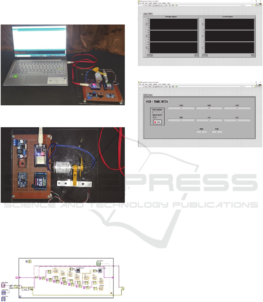
level of accuracy that meets the standards. The circuit
built can be seen in Figure 4 for the schematic and
Figure 5. and 6 for its application.
Figure 5: Details of the circuit prototype connected to the
computer.
Figure 6: Circuit are made for measuring speed and torque.
The microprocessor processes the input voltage,
current, speed, and torque sensors, and the output can
be displayed on display or displayed to the computer.
One way is to use LabVIEW, as can be seen in
Figures 7, 8, and 9.
Figure 7: The Proposed system in LabVIEW.
Figure 8: Display output on LabVIEW.
Figure 9: Display output on LabVIEW.
The research on making this motor speed and
torque measuring instrument is intended for AC
motors in the electric motor lab of the Bali State
Polytechnic. Before that, the prototype was made
using a smaller engine. The measurement results of
voltage, current, speed, and torque produced can be
seen in Table 1 to Table 4, respectively.
Table 1 shows results data for testing of the
measuring voltage. The error results of the voltage
measurement are between 0.001 and 0.050 volts, with
an average error is 0.020 volts or 0.42%.
For the current measurement test, the result can be
seen in Table 2. The maximum error is only 0.01A or
1.6% when this device is used for 1A measurement,
while the minimum error is zero. For the test from
0.1A to 1A, the average error is only 0.35 A.
The speed meter is tested by comparing the result
with the standard ones, and the results can be seen in
Table 3. The test is conducted for various speeds at
10 to 5500rpm. From Table 3, the error increases
gradually as the increase of speed of the motor. The
minimum error for speed testing is 0.01 rpm at the
lowest speed test of 10 rpm, while the maximum error
is 6.85 rpm at 5500 rpm, or it is only 0.22% of error.
The average error test for the speed meter is only 1.81
rpm or 1.11% of the measurement. This means that
the speed meter has a good performance with an
average error is less than 2%.
The test has also been conducted on the torque
meter, with the result shown in Table 4. The torque
A Simple Speed and Torque Meter using Arduino
713

values for the test are from 1 Nm then gradually
increased with 0.5 to get a higher value at 7 Nm. The
results show that the maximum error is found at the
maximum value of 1.87% and the minimum is only
0.08 %. The average error is less than 1% or 0.81%,
which makes this measurement device has a good
performance.
Table 1: Voltage measuring instrument testing.
Voltage (V) Error
Standard Measurement Value %
1.000 1.012 0.012 1.20%
2.000 2.001 0.001 0.05%
3.000 3.030 0.030 1.00%
4.000 4.020 0.020 0.50%
5.000 5.010 0.010 0.20%
6.000 6.013 0.013 0.22%
7.000 7.050 0.050 0.71%
8.000 8.037 0.037 0.46%
9.000 9.015 0.015 0.17%
10.000 10.012 0.012 0.12%
11.000 11.030 0.030 0.27%
12.000 12.011 0.011 0.09%
Average 0.020 0.42%
Minimum 0.001 0.05%
Maximum 0.050 1.20%
Table 2: Current measuring instrument testing.
Current (A) Error
Standard Measurement Value %
0.100 0.100 0.000 0.00%
0.200 0.200 0.000 0.00%
0.300 0.300 0.000 0.00%
0.400 0.401 0.001 0.25%
0.500 0.508 0.008 1.60%
0.600 0.600 0.000 0.00%
0.700 0.702 0.002 0.29%
0.800 0.801 0.001 0.13%
0.900 0.902 0.002 0.22%
1.000 1.010 0.010 1.00%
Average 0.002 0.35%
Minimum 0.000 0.00%
Maximum 0.010 1.60%
In general, the measuring instruments that have been
built for current and voltage measurements are under
the standard. This also applies to the speed and torque
measurements device that meet the standard.
Table 3: Speed measuring instrument testing.
S
p
eed (r
p
m) Error
Standard Measurement Value %
10 10.01 0.01 0.10%
50 50.01 0.01 0.02%
100 100.03 0.03 0.03%
200 200.11 0.11 0.06%
300 300.05 0.05 0.02%
400 400.87 0.87 0.22%
500 500.76 0.76 0.15%
750 751.20 1.2 0.16%
1000 1002.10 2.1 0.21%
1250 1251.55 1.55 0.12%
1500 1500.98 0.98 0.07%
2000 2002.31 2.31 0.12%
3000 3003.22 3.22 0.11%
4000 4003.97 3.97 0.10%
5000 5005.01 5.01 0.10%
5500 5506.85 6.85 0.12%
Average 1.81 0.11%
Minimum 0.01 0.02%
Maximum 6.85 0.22%
Furthermore, the error value is not significant for
the current measurement, which is an average of
0.35% with a maximum of 1.6% and still below 2%,
as shown in Table 4.
Table 4: Torque measuring instrument testing.
Torque (Nm) Error
Standard Measurement Value %
1.00 1.001 0.001 0.10%
1.50 1.502 0.002 0.13%
2.00 2.018 0.018 0.90%
2.50 2.502 0.002 0.08%
3.00 3.021 0.021 0.70%
3.50 3.526 0.026 0.74%
4.00 4.017 0.017 0.43%
4.50 4.552 0.052 1.16%
5.00 5.046 0.046 0.92%
5.50 5.523 0.023 0.42%
6.00 6.107 0.107 1.78%
6.50 6.581 0.081 1.25%
7.00 6.825 0.125 1.87%
Average 0.040 0.81%
Minimum 0.001 0.08%
Maximum 0.125 1.87%
Testing speed and torque measuring instruments
have been carried out with adding the calibration to
iCAST-ES 2021 - International Conference on Applied Science and Technology on Engineering Science
714

ensure both meterings meet the standard. The result
found that these devices only have a maximum error
of 0.22% and 1.87% for the speed meter and torque
meter, respectively.
4 CONCLUSIONS
The speed and the torque meter are built using
Arduino Uno to make them inexpensive. These
measuring instruments have been tested for current
and voltage measurements. Both devices are under
the standard, with the maximum error at less than 2
%. The speed and torque meter are also shown a good
performance under the test with maximum error for
both instruments is 0.22% and 1.87%, respectively.
So, all the instruments meet the standard.
ACKNOWLEDGEMENTS
The Authors thank The Center of Research and
Community Service, Politeknik Negeri Bali, for
funding this research.
REFERENCES
Alger, P.L.; et al. (1949). 'Induction Machines' sub-ection
of Sec. 7 - Alternating-Current Generators and Motors.
Knowlton, A.E. (ed.). Standard Handbook for Electrical
Engineers(8th ed.). McGraw-Hill. p. 705.
Alsofyani, IM and Idris, NRN. (2016). Torque ripple
reduction and fast torque control in DTC of induction
machine using overlapping triangular-based constant
frequency torque controller. 2016 IEEE International
Conference on Power and Energy (PECon), Melaka,
Malaysia, 2016, pp. 194-198, doi: 10.1109/P
ECON.2016.7951558.
Avinash, S., Ravi, K.. (2013). Torque Slip Characteristics
of Induction Motor. Course Notes. Malnad College Of
Engineering
Elec-toolbox.com. (1999). Motor Formulas. Archived from
the original on 8 May 1999. Retrieved 1 January 2013.
Leitner, S., Krenn, G., Gruebler, H and Muetze, A. (2019).
Rheometer-based Cogging Torque Measurement for
Sub-Fractional HP Permanent Magnet Motors, 2019
IEEE Transportation Electrification Conference and
Expo (ITEC), Detroit, MI, USA, pp. 1-7, doi:
10.1109/ITEC.2019.8790471.
Liu, X., Liang, D., Du, J., Yu,Y and Yang, X. (2014). A
torque measuring method based on encoder for
permanent magnet synchronous machine. 2014 17th
International Conference on Electrical Machines and
Systems (ICEMS), Hangzhou, China, pp. 1510-1514,
doi: 10.1109/ICEMS.2014.7013730
Ma, P., Wang, Q., Li, Y., Jiang, S., and Zhao, M. (2021).
Research on Torque Ripple Suppression of the Slotted
Limited Angle Torque Motor. IEEE Transactions on
Magnetics, vol. 57, no. 2, pp. 1-6, Feb. 2021, Art no.
8200106, doi: 10.1109/TMAG.2020.3006018.
NEMA MG-1 2007 Condensed. (2008). Information Guide
for General Purpose Industrial AC Small and Medium
Squirrel-Cage Induction Motor Standards. Rosslyn,
Virginia US: NEMA. p. 29 (Table 11). Retrieved 2
December 2012.
NEMA Standards Publication (2007). Application Guide
for AC Adjustable Speed Drive Systems. Rosslyn,
Virginia US: NEMA. p. 6. Archived from the original
on 28 April 2008. Retrieved 2 December 2012.
NSW HSC Online. (2012). AC Motors. Charles Sturt
University. Archived from the original on 30 October
2012. Retrieved 2 December 2012.
Penton Media, Inc. (2007). Induction Motors.
electricmotors.machinedesign. com.. Archived from
the original on 2007-11-16. Retrieved 2016-04-12.
Sarwar, I., (2018). 3 Phase Smart Energy Meter using
Arduino. Engineer Experiences, 2018. [Online].
Available: http://engineerexperiences.com/3-phase-
smart-energy-meter-using-arduino.html. [Accessed 9
March 2019].
Sharma, T.R., and Y. Pal, Y. (2019). Direct Torque Control
of BLDC Drives with Reduced Torque Pulsations. 2019
3rd International conference on Electronics,
Communication and Aerospace Technology (ICECA),
Coimbatore, India, 2019, pp. 1242-1247, doi:
10.1109/ICECA.2019.8822141.
Simón-Sempere, V., Burgos-Payán, M. and Cerquides-
Bueno, J. (2015). Cogging Torque Measurement Using
the Electromotive Force in Surface-Mounted
Permanent-Magnet Motors. IEEE Transactions on
Magnetics, vol. 51, no. 7, pp. 1-10, July 2015, Art no.
8105910, doi: 10.1109/TMAG.2015.2394477
Steinmetz, .P., Berg, E.J. (1997). Theory and Calculation of
Alternating Current Phenomena. McGraw Publishing
Company. OL 7218906M.
Wang, X., Wang, Z., Xu, Z., Cheng, M. and Hu, Y. (2020).
Optimization of Torque Tracking Performance for
Direct-Torque-Controlled PMSM Drives with
Composite Torque Regulator. IEEE Transactions on
Industrial Electronics, vol. 67, no. 12, pp. 10095-10108,
Dec. 2020, doi: 10.1109/TIE.2019.2962451.
A Simple Speed and Torque Meter using Arduino
715
