
Design and Implementation of Zeta Converter based on PI-ABC
Controller as a Battery Charging Control System with Solar Panel
Putu Agus Mahadi Putra, Indra Ferdiansyah and Mochammad Machmud Rifadil
Electrical Engineering Department, Politeknik Elektronika Negeri Surabaya, Surabaya, Indonesia
Keywords: Solar Panel, PI-ABC Controller, Constant Voltage, Zeta Converter.
Abstract: The rapid development of innovation in the use of energy is one alternative that is used is to use sunlight.
Solar panels have an important role in producing renewable electrical energy by converting light energy into
electrical energy because of its abundant availability and low emissions which have relatively low output
efficiency. However, based on its characteristics, solar panels produce electrical energy that fluctuates
according to the amount of irradiance and temperature if operated under normal conditions, the power
generated from solar panels will not be maximal and have low efficiency. In addition, the output power of the
solar panel fluctuates because it is influenced by the level of light irradiation on the surface of the solar panel.
In this study, to maximize solar panel power output and reduce output ripple is to use a constant voltage
battery charging method using a zeta converter with a PI-ABC Controller as a solar panel output voltage
controller from a zeta converter in order to produce a constant charging voltage according to the set point
voltage of 14.4 volts. The output of the solar panel is the input from the zeta converter which is used to reduce
the voltage with the PI-ABC Controller with the constant voltage method applied to the battery charging in
order to increase efficiency in a fast response to battery charging. The output of the ABC controller which
functions as a tuner for the KP value on the PI-ABC controller has a fixed Ki value. The efficiency generated
during the close loop using the PI-ABC controller can reach 96.56%, while during the open loop system it
reaches an efficiency of 83.36%.
1 INTRODUCTION
Significant progress has been made over the last few
years with regard to research and development of
renewable energy systems. Among the various
renewable energy options available, solar energy is an
inexhaustible source of energy and potential energy
that is environmentally friendly so that it becomes an
interesting issue related to environmental protection
(Wolfe, 2018). Solar energy is one of the fastest
growing renewable energies and is a very promising
solution because it can reduce exhaust emissions of
conventional vehicles by 92%. In fact, solar energy
systems offer the advantages of low-cost fuel and
lower maintenance. To make the most of the panel
power, the voltage from the solar panel must be
conditioned because solar cells have a characteristic
graph between voltage, power and current. This
relatively low output efficiency is due to differences
in characteristics between solar panels and loads, and
inconsistent output voltages due to weather changes
that make the solar panel system non-linear (Indra,
2020). Therefore, a method is needed to maximize the
output power of the solar panel.
One of the methods used to maximize the power
output of the panel is to use a zeta converter as a DC-
DC converter. The most suitable converter to
overcome this weakness is the zeta converter which
is used to control the solar panel output voltage and
the duty cycle is very influential on the solar panel
output voltage. , the output current can be continuous
and free of ripples due to the presence of an inductor
on the output side, and lower switching (Hilmi, 2017).
The zeta converter is a dc-dc converter that has the
role of increasing and decreasing the voltage on the
output side with low voltage ripple (Ahana Malhotra,
2016). The zeta converter method has better
performance so that it can maximize the work of solar
cells to be more efficient and effective than other
methods (N. Sownya Smitha Raj, 2013). From the
problem of irradiance changes, it causes changes in
the output voltage of the solar panel and the duty
cycle greatly affects the output voltage of the solar
panel. So in this study, a constant output voltage
Putra, P., Ferdiansyah, I. and Rifadil, M.
Design and Implementation of Zeta Converter based on PI-ABC Controller as a Battery Charging Control System with Solar Panel.
DOI: 10.5220/0010955700003260
In Proceedings of the 4th International Conference on Applied Science and Technology on Engineering Science (iCAST-ES 2021), pages 869-875
ISBN: 978-989-758-615-6; ISSN: 2975-8246
Copyright
c
2023 by SCITEPRESS – Science and Technology Publications, Lda. Under CC license (CC BY-NC-ND 4.0)
869
controller was designed to output a zeta converter
output voltage. The proposed method is to design a
charging control system based on the PI-ABC
Controller algorithm to track the set-point response
and to reject interference due to external factors such
as changes in solar radiation intensity (D. Pilakkat,
2018). The PI-ABC Controller is used to regulate the
voltage, and the irradiation that will produce a duty
cycle and the output voltage of the solar panel will be
forwarded to the zeta converter for conversion to a
lower dc voltage. effective for controlling PWM
generation which functions to control the converter
output voltage so that it is constant and the battery
voltage can be controlled effectively (D. Pilakkat,
2018).
2 LITERATURE REVIEW
2.1 Zeta Converter
Zeta converter is a dc to dc converter in continuous
conduction operating mode (CCM)(D.W.Hart, 2011).
The zeta converter topology produces a positive
output voltage from the input voltage up and down.
Zeta converters also require two inductors and a
series capacitor, commonly referred to as a flying
capacitor. Zeta converter is configured from a buck
controller that drives a high-side PMOSFET. This
Zeta converter is run in CCM (Continuos Conduction
Mode) conditions. There are two circuits in one
switching period (T). When the switch is on and off.
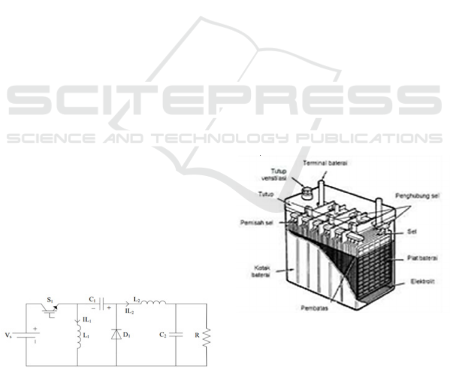
The zeta converter is shown in Figure 2.5. The zeta
converter consists of an IGBT transistor as a switch,
a diode and two capacitors C1 and C2 and two
inductors L1 and L2 with the current load R. in the
inductor increasing. When the switch is turned off,
the diode will transfer energy to the capacitor. In this
mode of operation, inductors L1 and L2 are in a state
of releasing stored energy. The energy released from
L1, is then charged to the capacitor C1 and the
inductor L2 transfers the energy to the output circuit
to the load.
Figure 1: Zeta Converter Circuit.
The working principle of the zeta converter is that
when the mosfet is off, the voltage that passes through
L1b must be the output voltage as long as it is parallel
to the output capacitor (Antonio, 2015). As long as
the output capacitor is charged by the output voltage,
the voltage across the mosfet when the MOSFET is
off is Vin + Vout even though the voltage across L1a
is -Vout relative to the drain of the MOSFET. When
the mosfet is on, the coupling capacitor is charged by
Vout which is connected in series with L1b, so the
voltage across L1b is +Vin, and diode D1 is
Vin+Vout. Figure 1, is a zeta converter topology,
from this picture you can find out the working
principle of the zeta converter.
2.2 Battery
A battery is a device consisting of two or more
electrochemical cells that convert stored chemical
energy into electrical energy. Batteries have two
types of direct current (DC) source elements from
chemical processes, namely primary elements and
secondary elements. A chemical reaction in the
primary elements that causes electrons to flow from
the negative electrode (cathode) to the positive
electrode (anode). Poles marked positive have a
higher potential energy while negative to the external
equipment. Electrolytes are ions producing chemical
reactions at both poles. The working principle of the
battery is if there is movement of the ions in the
battery that drains an electric current out of the
battery.
Figure 2: Battery.
iCAST-ES 2021 - International Conference on Applied Science and Technology on Engineering Science
870
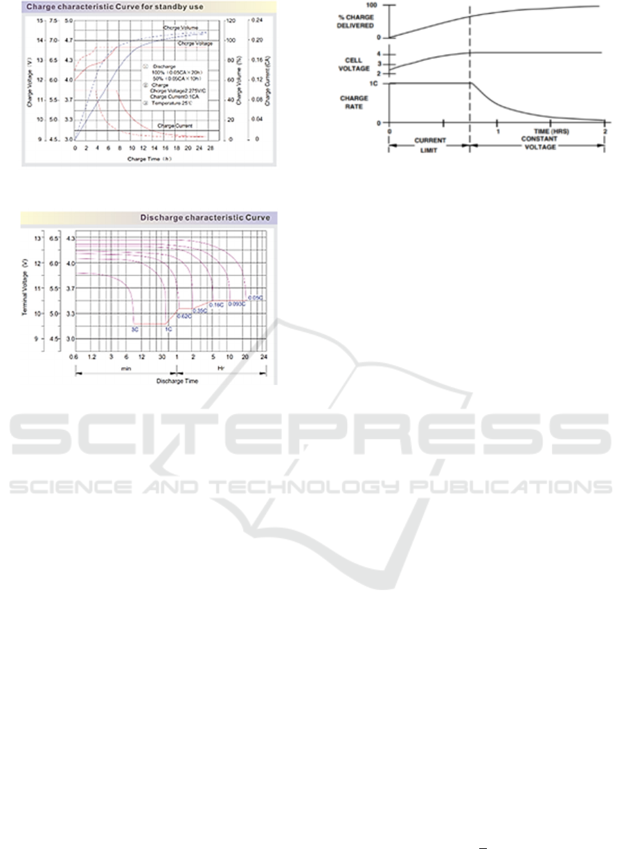
Figure 3: Charge characteristic Curve for standby use.
Figure 4: Discharge characteristic Curve.
2.3 Constant Voltage (CV)
There are various charging methods that can be used
for the charging circuit. The methods differ in the way
the electrical energy is delivered from the power
supply to the battery. This method is a charging
process that is carried out with a constant voltage
from the beginning to the end of the charging process
with the charging current continuing to decrease
(David, 2001). Constant Voltage (CV) in this study
the method used is a constant voltage during the
charging process through a current source into the
battery as an effort to force the battery voltage to
reach the set point. At the beginning of the charging
process with a large current, after a while the current
will decrease according to the process. charging the
battery until the current cannot flow so that the battery
will be full and the battery charging process is
complete. Figure 5, is a graph of the battery charging
method used when charging the battery.
Figure 5: Battery Charging Method.
2.4 State Of Charge (SOC) Battery
Calculation of State Of Charge (SOC) is charging and
balancing power on the battery. Estimation of the
SOC can avoid damage to the internal battery that can
result in overdischarged and overcharged. SOC can
display the available energy in percentage of battery
capacity that is utilized in the battery charging
process (Omnia S.S, 2019).
SOC measurement of the battery can be done in
several ways:
1. Voltage measurement can be carried out with a
voltmeter or voltage sensor at battery power at a
constant value
2. Measurement of Specific Graphity (SG) in this way
is carried out depending on changes in the weight
measurement of the active chemical.
3. Estimating SOC based on voltage by measuring
battery cell voltage as the basis for calculating SOC
or remaining battery capacity.
2.5 PI Control
PI Controller (Proportional Integral Controller) is a
controller that can determine the precision of an
instrumentation system with the characteristics of the
presence of feedback on the system. The PI controller
is a PID controller derivative where the derivative (D)
is an error. So the following equation is obtained:
ܭ
ܭ
ூ
݁݀ݐ (1)
Where K
P
and K
I
are proportional and the
integral gain is the error or derivative of the read value
(MV) of the set point (SP).
݁ൌܵܲെܯܸ (2)
The transfer function of the PI controller is given
below:
ܩൌܭ
ௌ
(3)
Design and Implementation of Zeta Converter based on PI-ABC Controller as a Battery Charging Control System with Solar Panel
871
General approach to PI tuning:
1. Initially set the gain integral to zero
2. Increase K
P
until the response matches the setpoint
3. Adjusting the K
I
gain until it is stable, there are no
errors that affect the setpoint
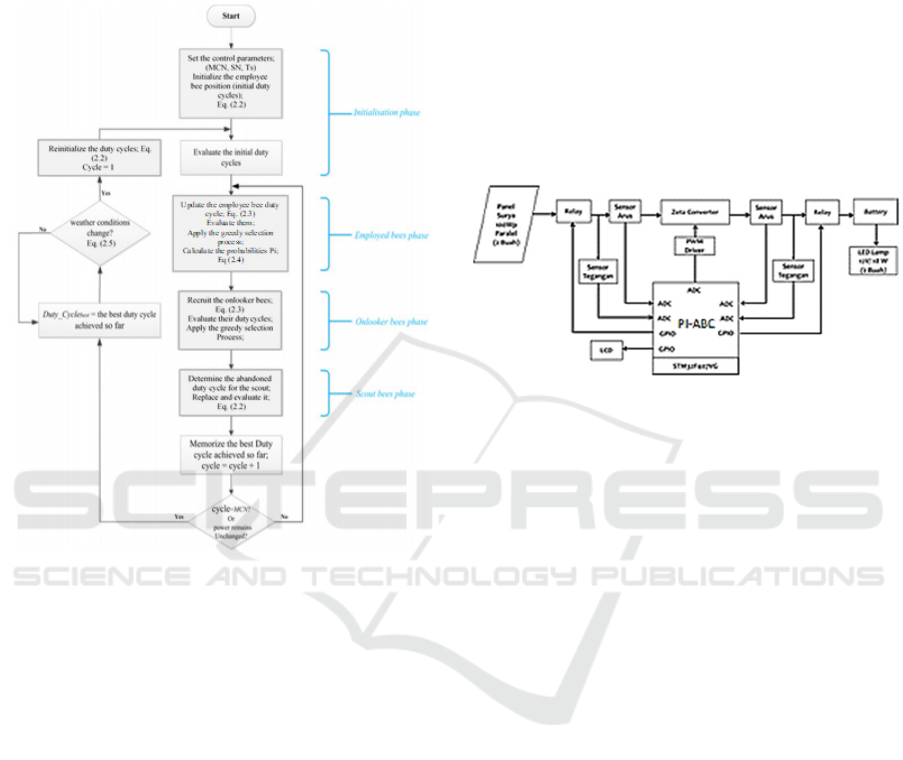
Figure 6: ABC Algorithm Flowchart.
2.6 Artificial Bee Colony (ABC)
In 2005, Dervis Karaboga introduced an optimum
algorithm called Artificial Bee Colony Algorithm,
which is based on the process of honey bees foraging.
ABC has three groups that are distinguished based on
their work. They are (A) employed bees, (B) onlooker
bees and (C) scout bees. Fifty percent of all bee
colonies consist of employed bees and another fifty
percent are onlooker bees (D. Pilakkat, 2018). The
ABC algorithm is stated as follows:
1. The first step, employed bees go to the location
where previously identified there is nectar.
2. Employed bees will communicate with each other
to notify the amount of nectar that has been found
through waggle dance, the location with the less
nectar amount will be forgotten and replaced with the
more nectar location.
3. Employed bees will pass the memorized location
on to the onlooker bees so that they go from hive to
location to collect nectar
4. Meanwhile Employed bees become scout bees who
go in search of new nectar locations.
In implementing the Artificial Bee Colony
algorithm on GMPP the output power of the PV
system is considered as the amount of nectar, and the
duty cycle ratio of the converter is referred to as the
position of the food source in the ABC algorithm. In
order to better explain the steps in the Artificial Bee
Colony algorithm, see the flowchart in Figure 6.
3 METHOD
Figure 7: System Block Diagram.
From Figure 7, the system diagram above, the
working principle is as follows:
In the block diagram there is a solar panel which
is a supply source that is connected to the system.
When the button is pressed, the system will control
the voltage to match the set point. The system is
equipped with a voltage sensor and a current sensor
located on the input side of the converter and from the
converter output it is used for sensing the ARM
STM32F4 microcontroller as a duty cycle control
reference for monitoring the amount of current and
voltage on the output side of the converter. In the
microcontroller the received data is processed and the
results are continued to the ADC (Analog to Digital
Converter).
The method used in the solar panel output voltage
system uses a converter circuit. The selection of
power efficiency on solar panels in this study can be
done using a zeta converter which can increase and
decrease the voltage according to the output output
from the solar panel. will be on as cut off to
disconnect charging. The system block diagram in
Figure 7 describes the order in which the system will
be created. Starting from the source of supply by
using solar panels to dc loads.
iCAST-ES 2021 - International Conference on Applied Science and Technology on Engineering Science
872
4 PI-ABC CONTROLLER
SYSTEM INTEGRATION
SIMULATION
Testing the PI-ABC Controller system with a battery
load is carried out with the aim of knowing the SOC
of the battery charging system with the constant
voltage method. In this battery charging simulation
using a 12V/45 Ah battery according to the design by
using SOC charging starting from 20% - 95%. battery
on PSIM software. The battery load used in the
following circuit uses a value of 12V/45Ah where the
parameters of the battery circuit are obtained from the
corresponding battery characteristic circuit in Matlab.
Figure 8 is a series of system testing simulations with
a Close-loop Battery Load.
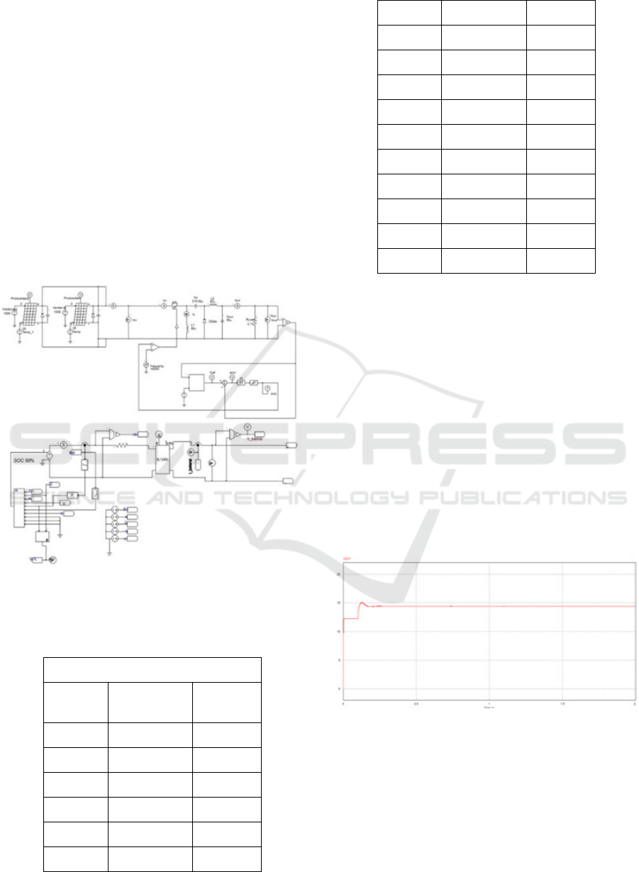
Figure 8: System Testing Simulation Circuit With Battery
Load In Close Loop.
Table 1: Close Loop Simulation Test Data With SOC
Battery.
Battery Load Close Loop Test
SOC
(%)
Vout(V)
Iout
(A)
20 14,4 5,32
30 14,4 4,347
40 14,4 3,59
45 14,4 3,282
50 14,4 3,01
55 14,4 2,75
60 14,4 2,48
65 14,4 2,227
70 14,4 1,983
75 14,4 1,694
80 14,4 1,389
85 14,4 1,07
88 14,4 0,849
90 14,4 0,713
92 14,4 0,592
94 14,4 0,408
95 14,4 0,323
From the data in Table I. Testing the system
simulation with a battery load in a close loop when
the SOC of the 12 V/45 Ah battery is close to full,
namely when the SOC is 95%, the condition of the
battery charging process to a constant voltage with a
charging voltage value of 14.4 V. This proves
whether the control of the PI control combined with
ABC works well when the charging voltage reaches
the set point constant voltage, the duty cycle will
continue to track so that the charging current
decreases. In accordance with the characteristics of
charging the battery, when the SOC of the battery
approaches 100%, the output current of the charging
process will approach 0 which means the battery is
fully charged. In Figure 8 is the output voltage
response when constant voltage
Figure 9: Output Voltage Response When Constant
Voltage.
Design and Implementation of Zeta Converter based on PI-ABC Controller as a Battery Charging Control System with Solar Panel
873
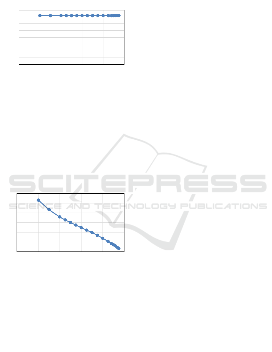
Figure 10: Output Voltage Response Graph With Close
Loop Battery SOC.
In Figure 10, there are outputs, namely constant
voltage testing and battery load testing in a loop,
whether the control is working as expected. While in
Figure 9. there is an output voltage response using a
battery load. At the same time, the control value is set
in the PI-control ABC by setting the Kp value so that
the output is constant at 14.4 Volts. This is in
accordance with the working principle of the charging
system where the output voltage is constant because
it uses a constant voltage method while the current
decreases. Figure 11 is a graph of the output current
response with the battery SOC.
Figure 11: Output Current Response Graph With Close
Loop Battery SOC.
In Figure 11. there is an output of the working
principle of the charging system where the output
current is against the SOC. In the graph it can be
analyzed that when the SOC of the battery is close to
100% (in full condition) with the control set in the
ABC control-PI it can be analyzed that the current
value of charging the battery (battery) will approach
0, according to the results of the battery close loop
simulation test data. using PSIM in table I, when the
initial SOC of charging the battery was recorded at
5.32 A, the parameter after the battery was full with
100% SOC recorded a current of 0.323 A. From the
graph of the output current response to the SOC of the
battery, it can be said that it is in accordance with the
characteristics of battery charging in general.
5 CONCLUSIONS
After carrying out the testing planning process and
analysis as well as comparing with supporting
theories, it can be concluded that: Controlling the
ABC-PI as a zeta converter output voltage controller
is able to have a value of set points (14.4 volts). The
average efficiency of taking Close loop data in
simulation with PSIM software can reach 94.6%.
When the system is given the influence of non-linear
photovoltaic characteristics, the system can control it
according to the set point, so it can be said that the
ABC-PI control can work well.
ACKNOWLEDGEMENTS
I express my deepest gratitude to all parties who have
helped in completing this paper, especially P3M
PENS and all members in this research.
REFERENCES
Ahana Malhotra, Shitiz Vij, Dr. Prerna Gaur, Charvi
Malhotra. (2016). “Design, Analysis and Performance
of Zeta Converter in Renewable Energy Systems”,
International Conference on Computing for Sustainable
Global Development (INDIACom), (IEEE).
Antonio M. S. S. Andrade, Luciano Schuch, Mário L. da S.
Martins.(2015).”Design and Simulation of Fuzzybased
DC-DC Interleaved Zeta Converter for Photovoltaic
Applications,”. In Federal University of Santa Maria,
UFSM (IEEE 2015), 978-1-4673-7554-2.
D. Pilakkat, S.Kanthalakshmi.(2018). " Artificial Bee
Colony Algorithm for Peak Power Point Tracking of a
Photovoltaic System under Partial Shading Condition,"
in Conf. Current Trends toward Converging
Technologies, Coimbatore, India.
D. W . Hart.(2011). “Power Electronics”, New York:
McGraw-Hill,.
David, Linden and Reddy, Thomas B. (2001), Handbook
Of Batteries, 3
rd
Edition, The McGraw-Hill Companies
Hilmi Zenk, Atilgan Altinkok. (2017).“Output Voltage
Control of PI And Fuzzy Logic Based Zeta Converter”
Department of Electrical Electronics Engineering,
Giresun University in Turkey (IJERA 2013),vol.
12,Issue 6, PP.2692-2696. Dec, 2017
Indra ferdiansyah,Ony Asrarul Qudsi,Fandi setiawan.
(2020). “Design of Baterry Charging System as Supply
0
2
4
6
8
10
12
14
16
0 20406080100
0
1
2
3
4
5
6
0 20406080100
Battery SOC – Output Voltage (V)
Output Voltage (V)
SOC(%)
Battery SOC – Output Current (A)
Output Current (A)
SOC(%)
iCAST-ES 2021 - International Conference on Applied Science and Technology on Engineering Science
874

of Rice Threshers in Tractor”, International Conference
on Apllied Technology and Innovation(ICAITI).
N. Sownya Smitha Raj, Smt.B. (2013).”PV fed Zeta
converter” International journal of Engineering
Research and Application(IJERA 2013),vol. 3,Issue 4,
pp.2692-2696, Jul-Aug 2013.
Omnia S. S. Hussian, Hany M. Elsayed, M. A. Moustafa
Hassan.(2019). “Fuzzy Logic Control for a Stand-Alone
PV System with PI Controller for Battery Charging
Based on Evolutionary Technique” in The 10 th IEEE
International Conference on Intelligent Data
Acquisition and Advanced Computing Systems
Technology and Applications,Metz, France 18-21
September 2019. 978-1-7281-4069-8
Wolfe, Phillip R. (2018). "What Is Photovoltaics?" The
Solar Generation: Childhood and Adolescence of
Terrestrial Photovoltaics. (pages 9 chapter 2). WILEY-
IEEE Press.
Design and Implementation of Zeta Converter based on PI-ABC Controller as a Battery Charging Control System with Solar Panel
875
