
A Comparison of Mini Pile Bearing Capacity based on Sondir Data
and Experimental Test
Efan Tifani
a
, Alamsyah
b
and Indriyani Puluhulawa
c
Department of Civil Engineering, Politeknik Negeri Bengkalis, Jl. Bathin Alam Sei Alam Bengkalis, Riau, Indonesia
Keywords: Mini Pile, Pile Capacity, Static Loading Test.
Abstract: The problem that arises due to the use of Mahang wood as a pile foundation is the exploitation of forest
products on a large scale. This is because building a two-story building requires 2-3 Mahang wood for every
square meter of the building. The replacement of Mahang wood into Mini Pile for building foundation is one
alternative solution to overcome this problem. In the implementation of the test, four mini piles measuring
12x12x250 cm were made, erection at two points with an embedded depth of 4.5 m. Static loading test has
been carried out to determine the actual capacity of the mini pile by loading the design load calculated using
the Bagemann method with CPT test data. The results showed the actual capacity of one point was 4.137 tons
with a settlement of 1.77 mm. This value was 2.81 times higher than the ultimate load (Pu) for the single pile
design based on the CPT test.
1 INTRODUCTION
One type of foundation that is commonly chosen by
the community in Bengkalis Regency to build a 2 to
4 story building is Mahang wood (Macaranginae)
with a length of 6 to 7 m. The use of that wood as a
foundation is almost the same as a concrete pile,
including the method of erection by a Drop Hammer.
This wood has been estimated to be strong in bearing
loads, easy to acquire and economical in its
application, especially in clay soil areas such as
Bengkalis Regency. Nevertheless, there has been a
problem of using forest products on a large scale only
to build 2 to 4 storey buildings which require 2-3
mahang wood for every square meter of building.
Replacing mahang wood with mini pile concrete for
building foundations is an alternative to reduce these
problems. Where the mini pile has dimensions that
can be adjusted to the needs, has strong resistance and
quality can be controlled.
a
https://orcid.org/ 0000-0001-9358-3513
b
https://orcid.org/0000-0002-0766-1712
c
https://orcid.org/0000-0001-6588-1345
2 LITERATUR STUDY
Mini Pile is one type of pile foundation that is used to
support the foundation of a construction such as
bridges, docks, buildings, dolkens and others. The
shape of the mini pile is generally in the form of a box
or triangle with a cross section variation of 20 x 20
cm to 40 x 40 cm and a length variation between 3m
to 9m. If a longer length of the mini pile is needed, it
can be connected to a welded iron plate (Pamungkas
E.T, et al, 2021).
2.1 Sondir Test
Sondir test, also known as Cone Penetration Test
(CPT) is often used to estimate the bearing capacity
of soil in deep foundations. However, it is sometimes
also used to estimate the bearing capacity of shallow
foundations. This has been confirmed by Eslami
2020, that the conus end resistance in the CPT test is
the same as the pile end resistance. The test is carried
out by pushing the cone into the ground. The soil
resistance at the tip of the cone as well as the soil shaft
friction was measured. So that the value of the cone
988
Tifani, E., Alamsyah, . and Puluhulawa, I.
A Comparison of Mini Pile Bearing Capacity based on Sondir Data and Experimental Test.
DOI: 10.5220/0010957700003260
In Proceedings of the 4th International Conference on Applied Science and Technology on Engineering Science (iCAST-ES 2021), pages 988-994
ISBN: 978-989-758-615-6; ISSN: 2975-8246
Copyright
c
2023 by SCITEPRESS – Science and Technology Publications, Lda. Under CC license (CC BY-NC-ND 4.0)

resistance (q
c
) and friction data (f
s
) is obtained
(Fahriani F, 2015).
There are two types of sondir, the first is the light with
a capacity of 0-250 kg/cm² and the second is the
heavy with a capacity of 0-600 kg/cm². The type of
soil that is suitable for sondir with this tool is soil that
does not contain rocks (Hairina R).
2.2 Bagemann Method
According to Yusti, 2014, piles on cohesive soil
generally have conical resistance (q
c
) related to
undrained cohesion (c
u
), namely:
.
=
(kg/cm
2
)
(1)
The value of N
k
ranges from 10 to 30, depending on
the sensitivity, compressibility and adhesion between
the soil and cone. Generally in design calculations
using Nk between 15 to 20. The pile end resistance is
taken at the average q
c
value calculated from 8D
above the pile base to 4D below the pile end. Safely,
the frictional resistance of the unit area (f
s
) of the pile
can be taken as equal to the frictional resistance of the
cone side (q
f
):
=
(kg/cm
2
)
(2)
The ultimate capacity of the pile, expressed by the
equation:
=
.
+
.
(3)
Where
is area of the bottom end of the pole (cm
2
);
is pile blanket area (cm
2
);
= f
is conus
resistance (kg/cm
2
);
is frictional resistance of cone
side (kg/cm
2
).
The ultimate bearing capacity of the pile (Q
u
), is
calculated by the general equation:
=
+
=
.
+
.
(kg)
(4)
Where
is pile unit end resistance (kg/cm
2
);
is pile
unit friction resistance (kg/cm
2
).
2.2.1 Ultimate End Resistance
The ultimate capacity of the pile embedded in the
cohesive soil is the sum of the side frictional and the
end resistance of the pile. The amount of frictional
resistance of the pile depends on the material and
shape. Generally, for homogeneous soils, the
frictional resistance of the walls in the form of
adhesion between the pile side and the soil will have
a large effect on the ultimate capacity.
=
.
(5)
=
(6)
Where
is cohesion in undrained soil conditions
located below the pile end whose values are taken
from undisturbed soil samples (kN/m
2
);
isbearing
capacity factor (function of φ).
For cracked clay, c
b
must be taken from the shear
strength of cracked clay. Reduction due to cracked
soil conditions needs to be given, because this effect
reduces the contact between the pile side and the soil.
For piles embedded in soft to medium clay soils, the
end resistance value is usually not large, so the
method of calculating the bearing capacity of piles in
cohesive soils is generally more focused on
determining the pile frictional resistance (Q
s
).
2.2.2 Ultimate Wall Friction Resistance
To determine the frictional resistance of piles driven
in clay, the adhesion factor (α) collected by
McClelland (1974) is used as shown in Figure 1. The
frictional resistance of piles is expressed as follows:
=
.
(7)
=
=.
(8)
Where
is ultimate friction resistance (kN);
is
adhesion between the pole and the soil (kN/m
2
); is
adhesion factor is taken from Figure 1;
is average
undrained cohesion along the pile (kN/m
2
).
Figure 1: Adhesion factor (α) collected by McClelland
(1974).
2.2.3 Pile's Ultimate Bearing Capacity
The ultimate bearing capacity of the pile is calculated
by the following equation:
=
.
+
.
.
−
(kg)
(9)
A Comparison of Mini Pile Bearing Capacity based on Sondir Data and Experimental Test
989

Since the self-weight of the pile (W
p
) is close to the
weight of the soil displaced by the pile, A
b
.p
b
can be
considered equal to W
p
. Therefore, the pile bearing
capacity in cohesive soils becomes:
=
.
+
.
.
(kg)
(10)
Where
is shape factor of pile (equal to 1 for
uniform pile diameter).
2.3 Pile Foundation Settlement
According to Fahriany 2015, the estimation of
settlement that occurs in pile foundations is a
complicated problem caused by several factors, such
as disturbances in soil stress during erection and
uncertainty regarding the distribution and position of
load transfer from the pile to the soil.
=
100
+
(11)
Where S is single pile foundation settlement; D is pile
diameter; Q is pile bearing capacity; L is pole length;
A
p
is pile cross-sectional area; E
p
is modulus of
elasticity of concrete pile material.
2.4 Static Loading Test
According to Hardiyatmo, 2002, the static loading
test was carried out with several objectives, such as:
Determine the graph of the load and settlement
relationship, especially in the load around the
expected design load.
Ensure that foundation failure will not occur
before the target load is reached. Its value is
several times the design load. This value is used
as a safety factor.
Determine the actual ultimate capacity, check
the results of the calculation of the pile capacity
obtained from the static and dynamic formulas.
The standard test method for deep foundations
under static axial compressive load consists of 7
procedures, one of which is the slow maintained test
load method.
The Slow Maintained test load Method (SM Test)
is recommended by ASTM D1143-81, this method is
generally used in field research before further work is
carried out, the testing procedure consists of:
a. Pile load is divided into eight equal stages,
namely 25%, 50%, 75%, 100%, 125%, 150%,
175% and 200% design load
b. Each increase in load must maintain the rate of
descent which must be less than 0.01 in/hour
(0.25 mm/hour)
c. Maintain 200% design load for 24 hours
d. After the required time is reached, reduce the
load by 25% with a gap of 1 hour between
reduction times.
e. After the load has been applied and removed,
reload the pile for load testing in increments of
50% of the design load, allowing 20 minutes for
additional load.
f. Then increase the load in increments of 10% of
the design load.
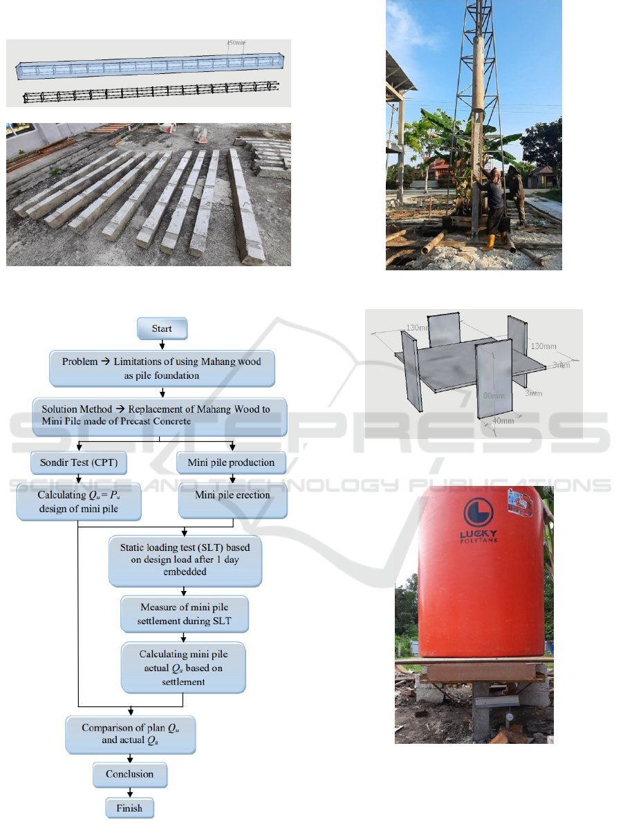
3 METHOD
The research stages are divided into several stages as
shown in Figure 3, and are described as follows:
a. Manufacture of mini pile specimens in the form
of a square cross section with a size of
12x12x250 cm, using 4Ø10 main reinforcement
and D6-200mm stirrup reinforcement as seen in
Figure 2. The composition of the mixture refers
to the regulation of the Minister of PUPR No. 28
of 2016 for the quality of K225. In addition,
several specimens of concrete cubes of
15x15x15 cm were also made to determine the
quality of the mini pile concrete.
b. Sondir testing was carried out at the location of
the mini pile to determine the cone resistance
data (q
c
) and cone side friction resistance (q
f
).
c. Calculate the amount of design load that will be
given to the mini pile during testing.
Determination of the carrying capacity of the
plan (Q
u
) using the Bagemann method by
analyzing the sondir test data.
d. Mini pile erection at a predetermined location
using a Drop Hammer (Figure 4). One point of
the foundation using two mini piles with steel
plate connection as shown in Figure 5. The
depth of the pile is 2x2.5 m but the embedded
depth of the mini pile is 4.5 m, which is 0.5 m
not embedded as the set up of loading test.
e. The loading test was carried out based on the
SM Test. Static load testing was carried out for
two days with a load of 25, 50 ,75 and 100% of
the design load. Then let stand for 24 hours and
the load was reduced gradually. This load was
given to determine the actual settlement that
occurs in the mini mile based on the carrying
capacity of the plan achieved. To facilitate load
application, two mini pile points were placed at
iCAST-ES 2021 - International Conference on Applied Science and Technology on Engineering Science
990
a distance of 10 D or 120 cm as shown in Figure
6.
Figure 2: Mini pile specimens.
Figure 3: Research flow chart.
Figure 4: Erection of mini pile by drop hammer.
Figure 5: Steel plate connection.
Figure 6: Static loading test of mini pile.
f. During loading, settlement that occurs in the
mini pile was recorded using a dial installed on
the mini pile (Figure 7).
A Comparison of Mini Pile Bearing Capacity based on Sondir Data and Experimental Test
991
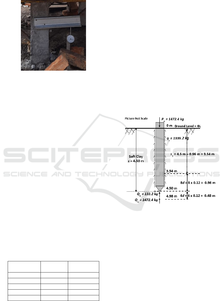
Figure 7: Recorder settlement using dial gauge.
g. The last stage is to determine the actual carrying
capacity (Q
u
) based on the real settlement during
testing and the actual mini pile's Elasticity
Modulus. Then compare the value of the actual
carrying capacity with the carrying capacity of
the plan.
4 RESULTS AND DISCUSSION
The results obtained are Sondir data, the quality of
mini pile concrete, the value of the ultimate bearing
capacity (Q
u
) of the single pile used as the design load
(P
u
), the settlement (S) of the test results by the SLT
method and the value of the actual ultimate bearing
capacity (Q
u
actual). The allowable load (P
a
) of a mini
pile/single pile with dimensions of 0.12 m × 0.12 m ×
4.50 m which is embedded on soft clay.
4.1 Sondir Test Results
The Sondir test was carried out to a depth of 12
meters, with a groundwater level of ± 0.75 m from the
ground level. Visual identification of soil types
categorized as soft clay. The data presented is only at
a depth of 1 to 5 meters, where the values of q
c
and q
f
have been averaged every one meter depth, as shown
in Table 1.
Table 1: q
c
and q
f
value.
Depth
(z = m)
average q
c
(kg/cm
2
)
average q
f
(kg/cm
2
)
0 – 1 1,3 0.073
1 – 2 0.9 0.04
2 – 3 0.4 0.020
3 – 4 0.4 0.0213
4 – 5 1.1 0.153
According to Galang M et al, 2017, the calculation of
pile capacity using CPT data shows the results closest
to the real capacity.
4.2 Concrete Quality Test
The results of testing the concrete cube at the age of
28 days obtained the average value of the concrete
compressive strength of 283.65 kg/cm
2
. This value
was 26% higher than planned. Furthermore, with this
value, the actual value of the concrete's modulus of
elasticity was 22804.93 MPa.
4.3 The Ultimate Bearing Capacity
Design (Q
u
) of Single Pile
The value of the ultimate bearing capacity (Q
u
) of a
single pile was obtained using the Bagemann method
as shown in Figure 8.
Figure 8: Mini Pile embedded.
=
+
=
= 0.0144
=
&
= 0.925/
=
×
= 0.0144
+ 92.5/
= 1.332~133.2
= 2.16
=
.
= 0.062/
=
×
= 2.16
+6.20/
= 13.392~1339.2
= 133.2 + 1339.2
=
= 1472.4~1.472
iCAST-ES 2021 - International Conference on Applied Science and Technology on Engineering Science
992

The value of Q
u
was applied as the ultimate load
design (P
u
) for the single pile to obtain the actual
settlement value of the pile during loading.
4.4 Settlement Value (S) Single Pole
Static loading test with full scale 1:1 was carried out
one day after erection. The ultimate load is Pu=1.472
tons ×2= 2994 kg for two single piles with a distance
(s) = 10d = 1.2 m. Although the application of the load
by the 2 poles is in one plate holder to facilitate load
balance, but with a distance between the poles of 10d
resulting in an efficiency value (E) of the pole = 1
(Hardiyatmo, 2012), the loading received by each
pole is still based on the load. The ultimate design for
the single (P
u
) pile is 1472 kg (not the group), as
shown in Figure 9.
Figure 9: Application of loading to the final settlement of
single pile.
The result of full loading of 1.472 tons per pile shows
the final actual settlement value of (S) = 1.77 mm or
equal to the ratio of 0.0147d (1.475% of the pile
width). Where the test results are depicted in a graph
of the relationship between the load and the
settlement, as shown in Figure 10.
The settlement shown is less than that required by
ASTM D 1143/D 1143M-07 in procedures B and C,
where the maximum pile settlement is 0.15d (15% of
the pile width), along with the failure of the pile.
Likewise with the 2015 Wrana Bogumil the
settlement that has occurred was not higher than 0.1d
when the maximum load has been reached.
Figure 10: Relationship between load and single Pile
settlement.
4.5 Actual Ultimate Capacity (Actual
Q
u
) Single Pile
This value is obtained by using the Vesic method
which is based on the final actual settlement (S) that
occurs, involving the value of the Elasticity Modulus
of the mini pile material (E
p
).
= 22804.93~22804930/
Furthermore, the value of the actual ultimate bearing
capacity (actual Q
u
) is as follows:
=
−
100
×
×
=
0.00177m −
0.12
100
4.50
× 0.0144
× 22804930/
= 0.000126 × 0.0144
× 22804930/
= 41.377~4.137
0,00
0,10
0,20
0,30
0,40
0,50
0,60
0,70
0,80
0,90
1,00
1,10
1,20
1,30
1,40
1,50
1,60
1,70
1,80
0 150 300 450 600 750 900 1050 1200 1350 1500
Settlement of mini pile (S)= mm
Loading (P) = kg
A Comparison of Mini Pile Bearing Capacity based on Sondir Data and Experimental Test
993

The data above shows that the value (actual Q
u
) is
2.81 times higher than the ultimate Q
u
(P
u
design) for
single pile.
4.6 Allowable Load (P
a
) Single Pile
The value of the allowable load (P
a
) is obtained from
the actual Q
u
by involving the safety factor (SF = 2.5).
The mini pile in this study was obtained as follows:
=
=
=
4.137
2.5
= 1.65
The value is a safe load value (P
a
) of 1.65 tons, in
accordance with what is required to be held by one
mini pile.
5 CONCLUSIONS
The results of the above studies can be concluded that
the actual final settlement value of the pile S = 1.77
mm has been obtained from the SLT test at the
ultimate load (P
u
) = 1472.4 kg for one pile. The
settlement value is less than that required by ASTM
D 1143/D 1143M-07 of 0.15d and is still below the
allowable settlement tolerance limit for pile
foundations of 25.4 mm (1 inch). If the continued
loading is higher than 2.994 tons for 2 piles, then the
highest actual Q
u
(close to field conditions) can be
achieved when the pile settlement approaches the
ASTM limit value and the allowable tolerance limit
value for the pile foundation, this can be seen from
the slope of the curve in the graph (Fig. 10) which is
getting steeper and the pile settlement is still large as
the load increases.
ACKNOWLEDGEMENTS
We would like to offer the special thanks to the
Bengkalis State Polytechnic (P3M) for funding this
research activity.
REFERENCES
Fahriani, F & Apriyanti, Y (2015). Analisis Daya Dukung
Tanah dan Penurunan Pondasi Pada Daerah Pesisir
Pantai Utara Kabupaten Bangka, Fropil Universitas
Bangka Belitung, 3(2), 89–95.
Galang M, Ferry F dan Muhardi, 2017. Analisis kekuatan
daya dukung pondasi Helical menggunakan data sondir
pada tanah gambut, Jom FTEKNIK, Vol.4 No.1, 1-7
Hardiyatmo, HC. (2010) Analisis dan Perancangan Pondasi
bagian II. Yogyakarta: Gadjah Mada University Press.
Yusti, A & Fahriani, F (2014). Analisis Daya Dukung
Pondasi Tiang Pancang Diverifikasi dengan Hasil Uji
Pile Driving Analyzer Test dan Capwap, Fropil
Universitas Bangka Belitung, 2(1), 19–31.
Wrana B., 2015. Pile Load Capacity – Calculation Methods,
Studia Geotechnica et Mechanica, Vol.37 No.4, 83-93.
ASTM. 2013, Standard Test Methods for Deep Foundations
Under Static Axial Compressive Load. ASTM D
1143/D1143M-07
Eslami A, Mosdfeghi S, MolaAbasi H, and Eslami M, 2020.
Piezocone and Cone Penetration Test (CPTu and CPT)
Applications in foundation Engginering, Elsevier, 1
st
edition.
Pamungkas E T, Gardjito E, Winarto S, Azhari F M., 2021.
Meningkatkan daya dukung tanah dengan pondasi mini
pile pada Gedung PT. Maju Jaya Kecamatan Ngasem
Kab Kediri, JURMATEKS, Vol.4 No.1, 30-43.
iCAST-ES 2021 - International Conference on Applied Science and Technology on Engineering Science
994
