
Development of Myoelectric Control Module for Prosthetic Hand
with Artifact Removal during Sensory Electrical Stimulation
Yashuo Yu
1a
, Chih-Hong Chou
1,2 b
, Jie Zhang
1c
, Manzhao Hao
1,2 d
and Ning Lan
1,2 e
1
School of Biomedical Engineering, Shanghai Jiao Tong University, Shanghai, China
2
Institute of Medical Robotics, Shanghai Jiao Tong University, Shanghai, China
Keywords: Prosthetic Hand, Sensory Feedback, Transcutaneous Electrical Nerve Stimulation (Tens), Stimulation Artifact.
Abstract: Evoked Tactile Sensation (ETS) with transcutaneous electrical nerve stimulation (TENS) can provide
amputees with a non-invasive neural interface for sensory feedback. However, sensory stimulation at the
projected finger map (PFM) on the stump skin causes interference in surface electromyographic (sEMG)
signals used for prosthesis control. This study developed a practical solution that combined hardware blanking
and software filtering to eliminate stimulus artifacts in real-time. A synchronized blanking circuit was inserted
after the differential amplifiers to partially remove artifact spikes. EMG signal was then sampled and further
processed by a digital signal processor (DSP). A digital comb filter removed the remaining artifacts at all
harmonic frequencies of stimulation. The filtered EMG was rectified, and its envelope was extracted to control
prosthetic hand. This technique was tested for its effectiveness in removing stimulus artifacts in three able-
bodied subjects and in one transradial amputee operating a Bebionic hand. Results in able-bodied subjects
indicated that the technique was effective in removing stimulus artifacts in EMG under different conditions.
In the amputee subject, grasp control using the Bebionic hand was obtained with simultaneous sensory
stimulation in the ipsilateral stump. The amputee subject achieved an average success rate of 90% for
identifying the length of grasped objects. Tests confirmed that the technique is adequate to remove stimulus
artifacts from EMG signals and allows control of the Bebionic hand with simultaneous sensory stimulation.
1 INTRODUCTION
Commercial prosthetic hands employ surface
electromyographic (sEMG) signals from residual
muscles for motor control. However, a survey of
amputees reported that the low prevalence and high
abandonment rate of such devices are attributed to the
lack of sensory function (Smail et al., 2021), which
plays an important role in the daily activities (e.g.
grasping tasks) for able-bodied subjects (Johansson &
Flanagan, 2009). Although there have been many
studies on closed-loop prosthetic systems in recent
years, the progress has been limited in the laboratory
(Bensmaia et al., 2020). Therefore, the restoration of
sensory function of a myoelectric-controlled bionic
hand has been a great challenge in neural engineering.
a
https://orcid.org/0000-0003-3512-4954
b
https://orcid.org/0000-0002-8985-5050
c
https://orcid.org/0000-0002-6075-2074
d
https://orcid.org/0000-0001-8744-7128
e
https://orcid.org/0000-0001-6061-5419
Our previous studies established that sensory
feedback delivered with transcutaneous electrical
nerve stimulation (TENS) to the projected finger map
(PFM) of the amputated stump can generate evoked
tactile sensation (ETS), and revealed that PFM on the
stump skin of the forearm of amputees corresponded
to the projection of the whole hand (Chai et al., 2015).
This afferent information shares a natural and direct
pathway with intact tactile afferents to the primary
somatosensory cortex (SI) (Hao et al., 2020). The
finger-specific perceptibility affords the advantage of
multi-facet recognition during prosthetic grasping (Li
et al., 2021).
In a closed-loop myoelectric prosthesis with non-
invasive sensory stimulation by TENS, it also
requires to collect sEMG signals for motor control,
118
Yu, Y., Chou, C., Zhang, J., Hao, M. and Lan, N.
Development of Myoelectric Control Module for Prosthetic Hand with Artifact Removal during Sensory Electrical Stimulation.
DOI: 10.5220/0010778600003123
In Proceedings of the 15th International Joint Conference on Biomedical Engineering Systems and Technologies (BIOSTEC 2022) - Volume 1: BIODEVICES, pages 118-125
ISBN: 978-989-758-552-4; ISSN: 2184-4305
Copyright
c
2022 by SCITEPRESS – Science and Technology Publications, Lda. All rights reserved
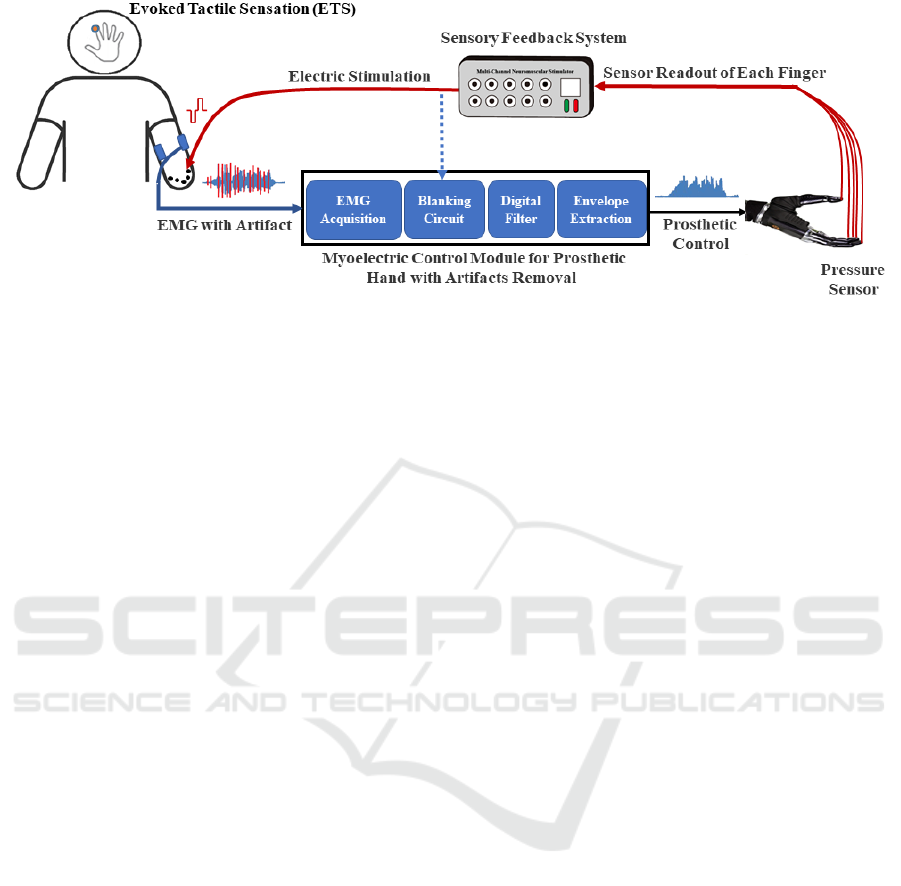
Figure 1: System block diagram of the integrated myoelectrical control and ETS-based sensory feedback of a Bebionic
prosthetic hand.
where the placement location of sEMG sensors
and stimulation electrodes are very close to each other
at the stump ipsilaterally. Stimulation artifacts
conducted through the skin and muscles can produce
a stimulus artifact much larger than EMG signals
from voluntary contractions. Accordingly, a major
drawback of TENS applied to the stump skin is that it
generates interference to sEMG signals.
A simple way to handle EMG contaminated with
stimulus artifacts from hardware is to wait for the
recovery of EMG amplifiers from saturation, which
requires a fast recovery of electronic components or
to switch off the amplifier (mute) when the stimulus
pulse starts to be delivered and discard the data during
saturation (Schauer et al., 2004). Besides, sample and
hold circuit can also be used for removal by storing
the DC levels before the pulse and holding it during
the pulse (Babb et al., 1978).
Software-based approaches combining
embedded processors allow for real-time or semi-
real-time removal. Software algorithms for real-time
processing need not only to achieve further
enhancements than hardware processing but also to
ensure instantaneity, which requires appropriate
complexity. However, most of algorithms for post-
processing focus on improving the algorithm
accuracy instead of efficiency. The software methods
for suppressing EMG signal artifacts can be broadly
classified into the following categories according to
the existing research: 1) blanking (Yi et al., 2013; Li
et al., 2019), 2) comb filter (Frigo et al., 2000;
Widjaja et al., 2009), 3) adaptive filter (Qiu et al.,
2015), and 4) other methods (Yochum et al., 2014;
Pilkar et al., 2016; Bi et al., 2021).
Dosen et al. (Dosen et al., 2014) used a time-
division multiplexing (TDM) approach with similar
logic to sample and hold, performing stimulation and
recording in dedicated, non-overlapping time
windows to avoid interference, and thus building a
real-time closed-loop control system.
The various solutions of artifacts removal are not
readily available for practical use in closed-loop
control prosthetic systems. In this study, we
developed and tested a module composed of a hybrid
method of hardware blanking and software filtering
to remove stimulus artifacts in sEMG caused by
TENS. This technique can allow integration of
control of myoelectrical prosthesis with the ETS-
based sensory feedback in the ipsilateral stump of
amputees. We verified this method with a
commercially available Bebionic hand to form a
closed-loop system. Test results indicated that the
prosthesis works properly with simultaneous sensory
perception of grasp, demonstrating that sensory
feedback adds the functionality of the device. The
system block diagram is shown in Figure 1. The blue
line represents control pathway, and the red line
represents sensory feedback pathway.
2 METHODS
2.1 Module Overview
The framework of the myoelectric control module for
prosthetic hand with artifact removal is shown in the
block diagram in Figure 2. In the control pathway, the
EMG signals from residual muscles are collected with
surface electrodes. The signals are blanked (switch
off) by a hardware circuit during stimulation and
filtered to remove the remaining artifacts. The
processed EMG signals are rectified, and the
envelopes are used to control the opening and closing
of prosthetic hand. EMG sampling, artifact filtering,
rectifying and envelope extraction are all processed in
Development of Myoelectric Control Module for Prosthetic Hand with Artifact Removal during Sensory Electrical Stimulation
119
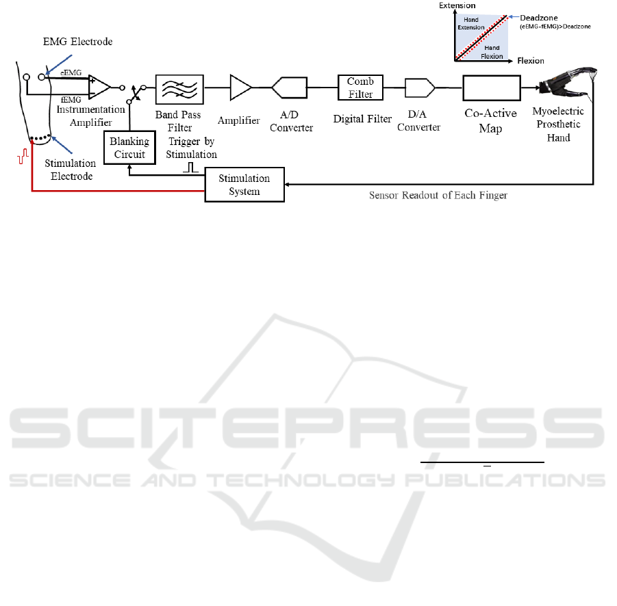
Figure 2: The hardware block diagram of the myoelectric control module.
a digital signal processor (DSP). In the sensory
pathway, contact pressures at prosthetic fingertips are
converted to a pattern of electrical stimuli and
delivered to five stimulation electrodes via the multi-
channel stimulator, which can generate specific
stimulation patterns according to an encoding
protocol. The stimulation patterns are charge-
balanced biphasic rectangular pulse trains with
positive pulses going first. Sensory intensity is
modulated by pulse amplitude (PA), pulse frequency
(PF) and pulse width (PW). Changes in stimuli
parameters can cause different sensory modalities, as
in (Yang et al., 2020).
2.2 System Description
To reduce the effect of the electrical stimulus on the
signal acquisition, we designed a blanking circuit to
turn off the electrical stimulus input to avoid the
current saturating the capacitor. We also moved the
switch to the output of the instrumentation amplifier
(OPA2333, Texas Instruments, USA) for reducing
the signal noise during switching (Rolston et al.,
2009). The architecture of the system is shown in
Figure 2.
When grasping occurs, the sensor in the prosthetic
hand generated the electrical stimulation signal. The
output of the stimulation sent the electrical
stimulation trigger to the blanking circuit
simultaneously. Then, the system turned off the meter
amplifier output within 10 μs, and conversely turned
on the acquisition function within 10 μs after the
electrical stimulation ends.
The subsequent part is a typical EMG signal
processing circuit. After band-pass filtering and A/D
conversion, the signal was processed with the comb
filter (refer to details in Section 2.3) implemented by
DSP. Then, the EMG envelope features were
extracted. Finally, the signal through co-active
mapping of one pair of antagonistic muscles was used
as the output control of the prosthesis. In addition, a
dead zone was set to avoid driving prosthesis under
weak EMG, which may lead to frequent jitter.
2.3 Signal Processing
After being propagated as local currents, stimulation
pulses manifest in the frequency domain as a
fundamental wave of the pulse delivery frequency
and its higher harmonics, which can be removed with
a comb filter with the following equation,
𝑦
(
𝑛
)
=
𝑥
(
𝑛
)
−𝑥
(
𝑛−𝑁
)
√
2
(1)
where x(n) and y(n) are for the raw and the filtered
EMG at sampling time n. N
Tstim
is the number of
samples between inter-pulse-intervals (IPIs). The
scale factor √2 can keep the signal power constant
after filtering (Frigo et al., 2000).
Then EMG signals were then filtered through a
6th Butterworth lowpass filter with a 400 Hz cutoff
frequency to reject high frequency components.
Finally, the signals were rectified and filtered with
2nd lowpass Butterworth with 10 Hz cutoff to extract
envelope curves.
All filters were implemented on a DSP
(STM32H743, STMicroelectronics, Italy) to provide
real-time operation.
3 EXPERIMENTS
3.1 Subjects
Three able-bodied subjects (2 males and 1 female,
29±6.083 yrs.) and 1 transradial amputated subject
(male, 54 years old, left amputation) were recruited to
BIODEVICES 2022 - 15th International Conference on Biomedical Electronics and Devices
120
participate in this study. All the experiment protocols
were approved by the Institutional Review Board for
Human Research Protections, Shanghai Jiao Tong
University.
3.2 Experiment Setup
The subject was seated at a table, and a Bebionic hand
(Otto Bock HealthCare) was fixed with an upright
tripod. Two pairs of bipolar EMG electrodes
(Norotrode 20 Bipolar sEMG Electrodes) were
placed on ulnar/radial side of forearm near elbow end
to capture two-channel EMG signals of wrist
flexor/extensor. The prosthetic hand was set to close
when the flexor contracted and to open with extensor
contraction (Figure 3 (a)). A non-invasive stimulation
pattern generator (Liu et al., 2015), delivered five
channels of TENS to five metal stimulation electrodes
on the forearm skin (Figure 3 (b), (c)) for able-bodied
subjects or the stump PFM site (for amputees)
corresponding to pressures (meansured by force
sensor, FlexiForce A201, Tekscan, Inc., USA) on
each digit tip (Figure 3 (d)). The stimulation electrode
was a disk Ag/AgCl electrode with 10 mm diameter,
custom made by the Institute of Semiconductors of
the Chinese Academy of Sciences. The reference
electrode (non-woven fabric circular electrode with 5
cm diameter) of each channel was placed near the
olecranon. The system equipped with EMG
acquisition function can output two channels of co-
active mapped execution signals to manipulate the
prosthesis. Both stimulation and EMG processing
were controlled by a host PC with self-innovate
software designed by C#. The two-channel EMG
signals were sampled at 2 kHz.
3.3 Experiment Protocols
There were two experiments in total. In the first
experiment, the able-bodied subjects explored
whether artifact removal strategies were effective
under different settings, and the second experiment
was carried out to verify the ETS-based sensory
feedback in real-time for closed-loop control on
amputees, which can be seen as a variant of (Li et al.,
2021) but in ipsilateral.
The 50 Hz fixed stimulation frequency was used
throughout the experiment, while pulse amplitude
(PA) and pulse width (PW) were modulated to encode
prosthetic hand contact pressure (Yang et al., 2020).
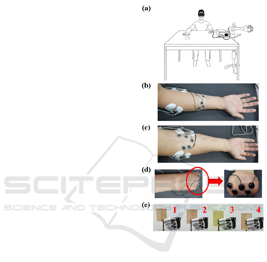
Figure 3: (a) Experiment scene. (b) and (c) show far and
near electrode distances respectively on able-bodied
subjects while (d) shows the amputee’s electrode sites with
stimulation electrodes on PFM. (e) 4 blocks of different
lengths (VS, S, M, and L) used in experiment 2, allowing
contact of different numbers of fingers. Fingers involved in
pinch are, from left to right: thumb and index thumb, index
and middle; thumb, index, middle and ring; thumb, index,
middle, ring and little.
3.4 Experiment 1: Filtering Algorithm
Validity Test
There were two conditions of stimulation electrode
placement: 1) far condition: stimulation electrodes
were placed between one half and three quarters
(distal end) of the full length (measured by the
distance from olecranon to ulnar styloid process) of
the forearm far from the EMG electrodes (Figure 3
(b)); 2) near condition: between two EMG electrodes
Development of Myoelectric Control Module for Prosthetic Hand with Artifact Removal during Sensory Electrical Stimulation
121

(Figure 3 (c)). The former condition was determined
according to the actual length of amputees’ residual
limb. The stimulation intensity level was set with a
PW of 600μs per channel. Then the PA of each
channel was set to the upper limit value of buzz
sensation multiplied by 0.8 when 5 channels
delivering simultaneously to avoid
uncomfortableness.
The experimental task was designed to meet the
practical application of the prosthetic for hand
opening and closing movement. The subjects
recorded their EMG by flexing/extending their wrist
for about 2s with stimulation. Ten trials for each
combination of electrode distances and
flexion/extension, that was 40 trials in total for each
subject.
Power generated by stimulus artifacts was further
quantified. First, EMG of able-bodied subjects was
segmented, and each segment contained 4000 sample
points (2 s signal sampled at 2 kHz). Then the power
spectral densities (PSD) were calculated by Welch’s
method. Eventually the PSD at each artifact harmonic
with 10Hz on each side was accumulated to estimate
the artifact power (P
stim
) with Eq. (2),
𝑃
𝑠𝑡𝑖𝑚
= 𝑃𝑆𝐷
(
𝑖
)
𝑘∗𝑓
𝑠𝑡𝑖𝑚
+10
𝑖=𝑘∗𝑓
𝑠𝑡𝑖𝑚
−10
𝑓𝑠/(2∗𝑓
𝑠𝑡𝑖𝑚
)
𝑘=1
(2)
where k is the number of harmonics and i is the
specific value of the discrete spectrum.
The averaged P
stim
in every condition over all
subjects was calculated. And the electrode distance
was considered as an intra-class factor to compare the
mean P
stim
, whose significant differences were tested
with two-tailed paired Tukey’s honestly significant
difference test.
3.5 Experiment 2: System Operation
Validation Test
In experiment 2, a response button was placed on
amputated subject’s contralateral hand. The
experimental task was to bend the wrist so that the
prosthetic hand can touch the wooden block when
closing. There were 4 different lengths of the blocks,
which could be represented by VS (very small), S
(small), M (medium), and L (large) respectively.
Hence, the number of fingers varied when the hand
grasped the block (Figure 3 (e)). During the contact
process between the prosthetic hand and the wood
block, the subject needed to determine the block size
by the finger numbers feeling through ETS. 5
channels of pressure signals, prosthetic hand aperture
(distance between tips of thumb and index), and the
response signal was sampled at 100 Hz synchronized
with EMG. Each grasping and identification make a
single trial and the experiment contained 40 trials in
total, with 10 trials for each size pseudo-random
ordered.
4 RESULTS
4.1 Effects of Artifact Removal at
Different Stages
The representative EMG signals at each processing
stage are plotted in Figure 4. Raw EMG without any
blanking is contaminated by a large amplitude of
stimulus artifacts with 1 channel of stimulation at 1
mA 200 μs. The artifacts do not saturate the
differential amplifiers. It is clear that artifacts are
significantly diminished with hardware blanking. It is
noted, however, that recording electrodes place
nearer to the stimulation electrodes yield fewer
artifacts than those with greater distance. Moreover,
contaminated EMG signals display artifact
components in all harmonic frequencies. After
processing by the comb and Butterworth filters,
artifacts of all harmonic components are largely
invisible in the filtered EMG. In spite of some loss of
EMG components at the harmonic frequencies, the
envelope of processed EMG signals can still be
extracted.
4.2 Filtering Algorithm Validity
Results
Figure 5 summarizes results across different
conditions in three able-bodied subjects. The vertical
axis shows spectral power in dB. Statistic analysis
indicates that P
stim
decreased along artifacts removal
stages regardless of muscle and the distance between
EMG and stimulation electrodes. It is clear that each
stage of hardware and software processing of this
method results in a certain degree of removal of
artifact components from the contaminated EMG. It
is expected that, artifacts power was the largest with
no blanking; and artifacts power is the smallest with
blanking and digital filtering. Artifacts are stronger
for EMG recording electrodes placed farther away
from the stimulation electrodes.
BIODEVICES 2022 - 15th International Conference on Biomedical Electronics and Devices
122
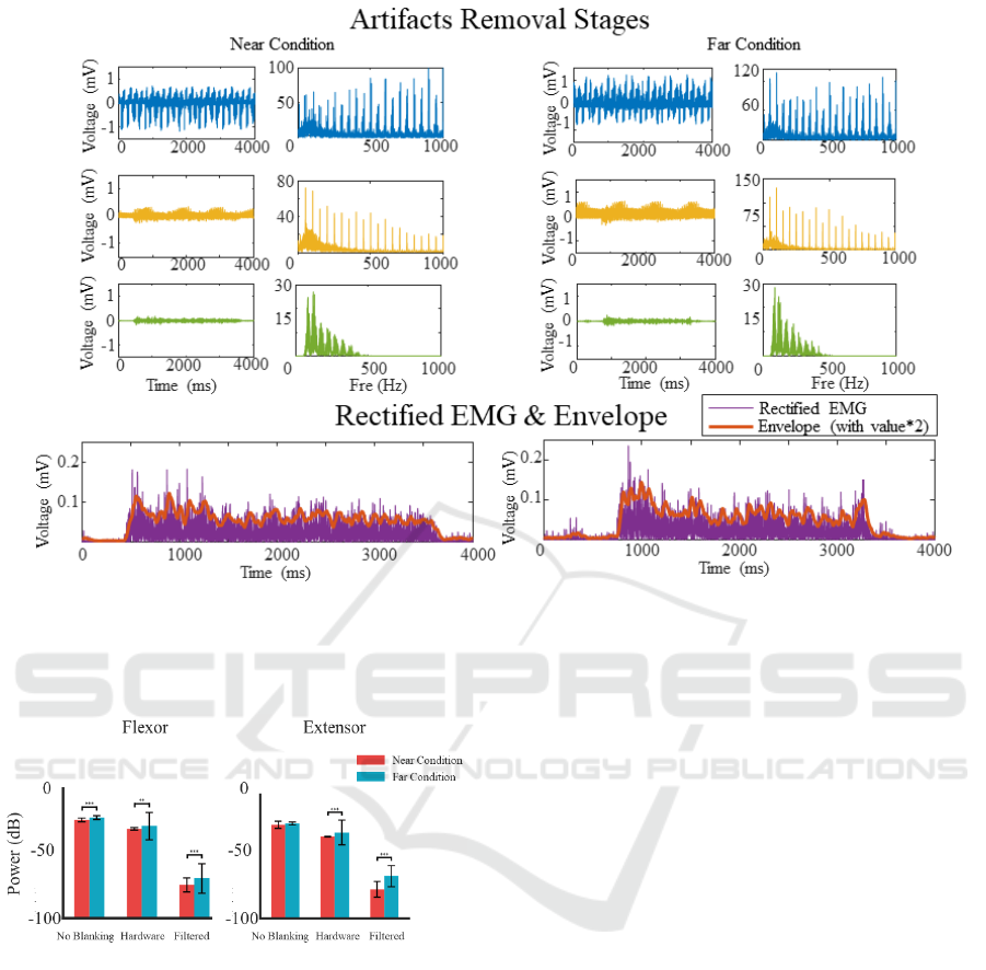
Figure 4: Extensor EMG signal and corresponding one-sided FFT spectrums at each processing stage. From top to bottom,
the respective stages are raw EMG without blanking, EMG with hardware blanking, EMG with software filtering, and the
final envelopes. The left and right columns are two cases where distance between stimulation and recording electrodes is near
and far with each other, respectively.
Figure 5: Bar plot of the harmonic power P
stim
(mean ±
standard deviation) shows the average results of 3 able-
bodied subjects across conditions. (Asterisks represent the
statistically significant difference between the near and far
intra-class conditions. **, p < 0.01; ***, p < 0.001).
Besides, all subjects show significant differences between
different stages and different electrode placement
conditions, which is not shown in the figure.
4.3 System Operation Validation
Results
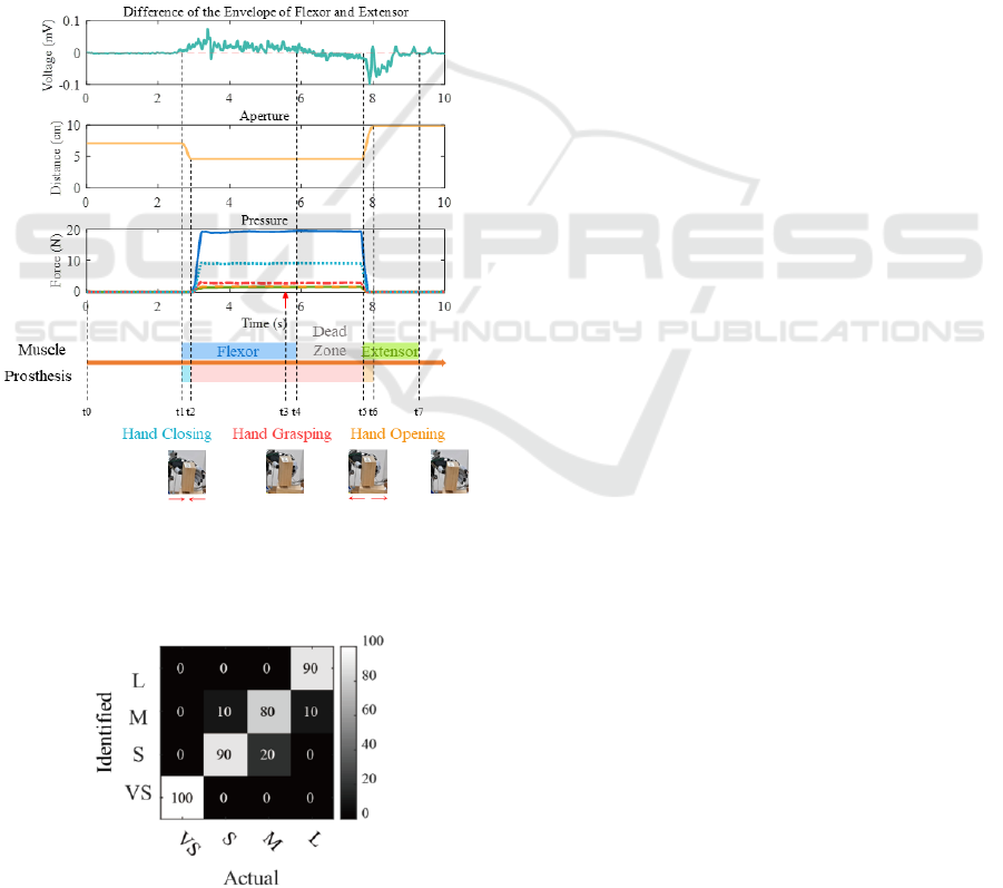
Figure 6 shows signals from both feedforward control
and sensory feedback of the closed-loop prosthetic
system.
It is shown that the difference between EMG
envelops of the flexor and the extensor increases
initially from zero to a positive value for hand
closing, then jitters around dead zone, later decreases
to a negative value for hand opening, and finally
returns to zero at resting hand posture. This implies
that control signals sent to the prosthetic hand first
close the hand for grasping the object and then opens
to release the object. This can also be seen from the
plots of hand apertures at the bottom of Figure 6. It
can be marked by several phases/timings (t0~t5). The
t0 is the beginning of trial (waiting state). The t1
stands for the start of flexor recruitment by amputee
for prosthesis operation. The EMG envelope
difference rapidly increases as the prosthesis begins
to close. The t2 stands for the timing that prosthetic
fingers contact with the block, at which the prosthetic
hand stops at the closing position, and the pressure
starts to rise. The red arrow indicates the size identify
response from the subject through ETS, and the
period between t3 and t1 represents identification
time. At the t4, extensor contraction starts. However,
the amplitude of EMG envelope difference between
t4 and t5 fails to reach the level to drive the prosthesis,
thus forming a dead zone. Then at hand opening stage
t5, the difference reverses to a sufficient value below
0. Finally, when the hand is fully open at t6, contact
pressure also drops along with the process.
Development of Myoelectric Control Module for Prosthetic Hand with Artifact Removal during Sensory Electrical Stimulation
123
During the hand closing phase, in the feedforward
pathway the envelope difference is positive,
corresponding to the subsequent rising in contact
pressure and sensory feedback and vice versa. The
correlations among these signals illustrate that the
closed-loop system is functioning as expected in real-
time in the grasping task.
Figure 7 shows the confusion matrix of size
identification by the amputee subject. The accuracy
of identification for VS, S, M, and L sizes are 100%,
90%, 80%, 90% respectively. It can be seen that in
general the rate of misjudgement increased with the
number of contacting digits. However, M size is the
most likely one to be misjudged. This result confirms
that grasping and perception can be performed
ipsilaterally and simultaneously with the closed-loop
control system.
Figure 6: The illustration of the output signals by amputee
and prosthesis phases during operation of the closed-loop
control system. The bottom illustrates the change in
prosthesis operation (hand apertures).
Figure 7: Confusion matrix presents the accuracy of size
identification.
5 DISCUSSION AND
CONCLUSION
This study applied a combination of hardware and
software processing for artifact removal from TENS.
The myoelectrical prosthetic hand can be integrated
with the ETS-based sensory feedback in real-time for
closed-loop control on ipsilateral side for amputees
without data segment or artifact template database
establishment. This enabled the user to operate the
prosthetic hand to grasp objects and obtain sensory
perception from specific fingers.
In order to remove stimulus artifacts caused by
TENS with a relatively large amplitude of stimulation
current, hardware circuitry of the EMG acquisition
was modified to blank the output of EMG differential
amplifiers in real-time triggered by stimulation pulses
at each pulse delivery. Test indicated that this method
eliminated part of stimulus artifacts, but allowed for
maximum retention of EMG signals. In addition,
digital filtering algorithms were adopted to remove
remaining artifacts using a DSP. The difference of the
envelopes of processed EMG signals was shown to be
adequate as instructions to control the commercial
prosthetic hand (Figure 6).
Results in Figure 5 indicate that stimulation
electrodes placed farther away from the recording
electrodes generated larger artifacts in the experiment
of this study. This may be due to the fact that stimulus
current trans-passed the recording electrodes. Thus,
the longer the distance between stimulation and
recording electrodes, the larger the volume resistance
between them, yielding a larger stimulus artifact. In
future applications, the reference electrodes for
stimulation may be relocated to other places to further
reduce the effect of stimulus artifacts.
Our study mainly shows that the receiving of
sensory feedback and the control of prostheses can be
integrated on ipsilateral side for amputees during
TENS pulses delivering. The technique can be
adequate to allow integrating myoelectric control of a
commercial prosthetic hand with ETS-based sensory
feedback, and can be further applied to other closed-
loop systems with interference between pathways.
There is still room to improve signal processing
methods. Other types of digital filters, such as
Bayesian filters, could be employed for artifacts
generated by higher stimulation frequencies. In
addition, the amplitude of EMG envelopes varies
with subjects and placement of EMG electrodes.
Thus, in future applications, parameters of envelope
gain should be adjustable according to each user for
optimal closed-loop operation of control and sensory
perception.
BIODEVICES 2022 - 15th International Conference on Biomedical Electronics and Devices
124

ACKNOWLEDGEMENTS
This research was supported in part by a grant from
Key-Area Research and Development Program of
Guangdong Province (2020B0909020004), the
National Key R&D Program of China (No.
2017YFA0701104, No. 2020YFC2007903), a grant
from the National Natural Science Foundation of
China (No. 81630050), and a grant from Science and
Technology Commission of Shanghai Municipality
(No. 20DZ2220400).
REFERENCES
Babb, T. L., Mariani, E., Strain, G. M., Lieb, J. P., Soper,
H. V., & Crandall, P. H. (1978). A sample and hold
amplifier system for stimulus artifact suppression.
Electroencephalography and Clinical
Neurophysiology, 44(4), 528–531.
Bensmaia, S. J., Tyler, D. J., & Micera, S. (2020).
Restoration of sensory information via bionic hands.
Nature Biomedical Engineering, 1–13.
Bi, Z.-Y., Zhou, Y.-X., Xie, C.-X., Wang, H.-P., Wang, H.-
X., Wang, B.-L., Huang, J., Lü, X.-Y., & Wang, Z.-G.
(2021). A hybrid method for real-time stimulation
artefact removal during functional electrical stimulation
with time-variant parameters. Journal of Neural
Engineering, 18(4), 046028.
Chai, G., Sui, X., Li, S., He, L., & Lan, N. (2015).
Characterization of evoked tactile sensation in forearm
amputees with transcutaneous electrical nerve
stimulation. Journal of Neural Engineering, 12(6),
066002.
Dosen, S., Schaeffer, M.-C., & Farina, D. (2014). Time-
division multiplexing for myoelectric closed-loop
control using electrotactile feedback. Journal of
NeuroEngineering and Rehabilitation, 11.
Frigo, C., Ferrarin, M., Frasson, W., Pavan, E., & Thorsen,
R. (2000). EMG signals detection and processing for
on-line control of functional electrical stimulation.
Journal of Electromyography and Kinesiology, 10(5),
351–360.
Hao, M., Chou, C.-H., Zhang, J., Yang, F., Cao, C., Yin, P.,
Liang, W., Niu, C. M., & Lan, N. (2020). Restoring
Finger-Specific Sensory Feedback for Transradial
Amputees via Non-Invasive Evoked Tactile Sensation.
IEEE Open Journal of Engineering in Medicine and
Biology, 1, 98–107.
Johansson, R. S., & Flanagan, J. R. (2009). Coding and use
of tactile signals from the fingertips in object
manipulation tasks. Nature Reviews Neuroscience,
10(5), 345–359.
Li, Y., Chen, J., & Yang, Y. (2019). A Method for
Suppressing Electrical Stimulation Artifacts from
Electromyography. International Journal of Neural
Systems, 29(06), 1850054.
Li, Y., Chou, C.-H., Zhang, J., Zhang, Z., Hao, M., & Lan,
N. (2021). A Pilot Study of Multi-Site Simultaneous
Stimulation for Tactile and Opening Information
Feedback in the Prosthetic Hand. 2021 10th
International IEEE/EMBS Conference on Neural
Engineering (NER), 187–190.
Liu, X. X., Chai, G. H., Qu, H. E., & Lan, N. (2015). A
sensory feedback system for prosthetic hand based on
evoked tactile sensation. 2015 37th Annual
International Conference of the IEEE Engineering in
Medicine and Biology Society (EMBC), 2493–2496.
Pilkar, R., Ramanujam, A., Garbarini, E., & Forrest, G.
(2016). Validation of empirical mode decomposition
combined with notch filtering to extract electrical
stimulation artifact from surface electromyograms
during functional electrical stimulation. 2016 38th
Annual International Conference of the IEEE
Engineering in Medicine and Biology Society (EMBC),
1733–1736.
Qiu, S., Feng, J., Xu, R., Xu, J., Wang, K., He, F., Qi, H.,
Zhao, X., Zhou, P., Zhang, L., & Ming, D. (2015). A
Stimulus Artifact Removal Technique for SEMG
Signal Processing During Functional Electrical
Stimulation. IEEE Transactions on Biomedical
Engineering, 62(8), 1959–1968.
Rolston, J. D., Gross, R. E., & Potter, S. M. (2009). A Low-
Cost Multielectrode System for Data Acquisition
Enabling Real-Time Closed-Loop Processing with
Rapid Recovery from Stimulation Artifacts. Frontiers
in Neuroengineering, 2.
Schauer, T., Salbert, R. C., Negard, N.-O., & Raisch, J.
(2004). Detection and Filtering of EMG for Assessing
Voluntary Muscle Activity during FES. 185–187.
Smail, L. C., Neal, C., Wilkins, C., & Packham, T. L.
(2021). Comfort and function remain key factors in
upper limb prosthetic abandonment: Findings of a
scoping review. Disability and Rehabilitation: Assistive
Technology, 16(8), 821–830.
Widjaja, F., Shee, C. Y., Poignet, P., & Ang, W. T. (2009).
FES artifact suppression for real-time tremor
compensation. 2009 IEEE International Conference on
Rehabilitation Robotics, 53–58.
Yang, F., Hao, M.-Z., Zhang, J., Chou, C.-H., & Lan, N.
(2020). An Experimental Protocol for Evaluating Pulse
Width Modulation Ranges of Evoked Tactile Sensory
Feedback in Amputees*. 2020 42nd Annual
International Conference of the IEEE Engineering in
Medicine Biology Society (EMBC), 3869–3872.
Yi, X., Jia, J., Deng, S., Shen, S. G., Xie, Q., & Wang, G.
(2013). A Blink Restoration System With Contralateral
EMG Triggered Stimulation and Real-Time Artifact
Blanking. IEEE Transactions on Biomedical Circuits
and Systems, 7(2), 140–148.
Yochum, M., Bakir, T., Binczak, S., & Lepers, R. (2014).
EMG artifacts removal during electrical stimulation, a
CWT based technique. 2014 IEEE Region 10
Symposium, 137–140.
Development of Myoelectric Control Module for Prosthetic Hand with Artifact Removal during Sensory Electrical Stimulation
125
