
Interactive Multimodal System Characterization in the Internet of
Things Context
Fabrice Poirier
1
, Anthony Foulonneau
1
, J
´
er
´
emy Lacoche
1 a
and Thierry Duval
2 b
1
Orange, 2 Av. de Belle Fontaine, Cesson-S
´
evign
´
e, France
2
IMT Atlantique, Lab-STICC, Brest, France
Keywords:
Multimodal Interaction, Tools, Internet of Things.
Abstract:
The internet of things (IoT) is a chance to provide users with pervasive environments in which they can interact
naturally with the environment. Multimodal interaction is the domain that provides this naturalness by using
different senses to interact. However, the IoT context requires a specific process to create such multimodal
systems. In this article, we investigate the process of creating multimodal systems with connected devices as
interaction mediums, and provide an analysis of the existing tools to complete this process. We discuss tools
that could be designed to support the creation process when the existing ones are not sufficient.
1 INTRODUCTION
Since Bolt experiment (Bolt, 1980), multimodal inter-
actions became a topic of interest to provide more nat-
ural and human-like interactions (Turk, 2014). This
naturalness comes from the selection of the most
appropriate modalities according to the context of
use (Caschera et al., 2015). Here, the context of use
refers to information about the target platform, the
user, and the environment (Calvary et al., 2005) that
can be used to adapt the interaction to each situation.
At the same time, we are increasingly surrounded
by smart devices networked to form the Internet of
Things (IoT). The IoT can provide to multimodal in-
teractive systems valuable interfaces to communicate
with end-users in smart environments (smart homes,
smart buildings, smart cities, etc.). Indeed, compared
to devices that are statically selected and associated
with specific user interactions (Ferri et al., 2018),
these devices are distributed, can be more numer-
ous, possibly mobile or carried, offer a wider range
of capabilities, and could be shared among multiple
stakeholders (e.g. administrators and employees in
offices) (Pruvost, 2013). Therefore, they contribute
to the realization of Weiser’s “ubiquitous computing”
paradigm (Weiser, 1991) in which computers vanish
from the users’ perspective and are considered as a
natural part of their environment.
a
https://orcid.org/0000-0003-3926-7768
b
https://orcid.org/0000-0003-4300-1671
However, the process of creating multimodal IoT-
based systems (hereafter referred to as MIBS) is still
complex. Indeed, MIBS are heavily dependent on
connected objects to interact with users. However,
from one smart environment to another, these objects
will be different, placed in different locations, with
different specifications. Moreover, the diversity of in-
teraction capabilities offered by the IoT leads to the
possibility of deploying a wide variety of interaction
techniques in such environments. All this has an im-
pact on the user-system interactions and more glob-
ally on the usability of the system. To evolve from
ad hoc solutions to a more generic and less expensive
MIBS creation process, it is necessary to make multi-
modal services independent from interaction devices,
as previously suggested by Avouac et al. (Avouac
et al., 2011). In this way, services can adapt to con-
nected objects in the smart environment where they
are deployed. The link between interaction devices
and multimodal services once deployed is referred to
as interaction chains. They include all the compo-
nents necessary for the interpretation and expression
of commands between the user and services.
Let us take the example of a service to book meet-
ing rooms in an office environment. In our exam-
ple, connected displays, presence sensors, and micro-
phones are installed in a crowded hall and each meet-
ing room. Each employee (i.e. end-user) has a profes-
sional smartphone and smartwatch that could be used
for the service. Based on these objects, several inter-
action techniques can be considered for the booking
142
Poirier, F., Foulonneau, A., Lacoche, J. and Duval, T.
Interactive Multimodal System Characterization in the Internet of Things Context.
DOI: 10.5220/0010817000003124
In Proceedings of the 17th International Joint Conference on Computer Vision, Imaging and Computer Graphics Theory and Applications (VISIGRAPP 2022) - Volume 2: HUCAPP, pages
142-153
ISBN: 978-989-758-555-5; ISSN: 2184-4321
Copyright
c
2022 by SCITEPRESS – Science and Technology Publications, Lda. All rights reserved

interaction. For instance, the method to select a room
could be to point at this room with a smartphone or
simply to enter the room and be detected by the corre-
sponding presence sensors. However, the administra-
tors’ choices aren’t known beforehand, and designing
services for each combination of devices would be too
burdensome due to the combinatory complexity.
The complexity to create such systems can be al-
leviated with software tools. Our goal is to provide
a comparative study of the existing tools to create
MIBS. However, these tools are not designed accord-
ing to a unique creation process, thus they are rarely
interoperable. Moreover, these tools only provide
support for specific tasks in their respective processes.
Therefore, we first need to propose a synthesis of the
processes to create MIBS.
For this purpose, we first introduce the tasks usu-
ally related to the MIBS life cycle. Then, we pro-
pose a literature review of the existing tools that cor-
respond to this life cycle and these tasks. Then we
discuss about the lack of tools in the creation process.
We finally conclude on the process and software tools
related to MIBS creation. We illustrate the different
tasks and analyze the existing tools with the meeting
room booking service previously presented.
2 TASKS RELATED TO THE LIFE
CYCLE OF MIBS
As expressed by the W3C community
1
, multimodal
systems are composed of the following elementary
components, which will be referred to as ”canonical
components” thereafter:
• Input and output modalities. The input modalities
detect the users’ actions, and the output modalities
transmit to the users the system messages, form-
ing the user interface (UI) in the process;
• An interpretation (including the fusion process)
component. Its role is to provide meaning from
the detected user’ actions;
• A dialogue manager. It reacts to the provided in-
terpretation and contextual information to further
the dialogue and decide what content to send back
to the user (Bui, 2006). The dialogue is the repre-
sentation of the service that the system must pro-
vide;
• A restitution (including the fission process) com-
ponent. It selects the most suitable output modal-
ities for the message to be sent back to the user;
1
https://www.w3.org/TR/mmi-framework/
• A context manager. It tracks changes in the con-
textual information and provides the necessary in-
formation to the other components.
The term UI has multiple definitions (Pruvost, 2013),
but we use the definition of the W3C which describes
it as the technology ”that allows users to effectively
perceive and express information”
2
. It includes, for
instance, graphical UI (GUI), vocal UI (VUI), or tan-
gible UI (TUI).
Several approaches exist in the literature to pro-
vide MIBS that can feature these canonical compo-
nents. In the next sections, we analyze these differ-
ent approaches to define the MIBS life cycle. As we
will see afterward, the proposed processes in the liter-
ature correspond to the systems development life cy-
cle (SDLC)
3
. Here, we consider that the requirement
specifications are already stated and we do not con-
sider the system end of life. Thus, we consider the
following stages to categorize and describe the pro-
cesses and their associated tasks in the literature:
• The design stage to describe all the system models
from the specified requirement;
• The development stage to create the necessary
software components according to the design;
• The integration stage to assemble the components
in a fully operational system;
• The deployment stage to install the system in the
desired environment;
• The operation and maintenance, or execution
stage to monitor the running system.
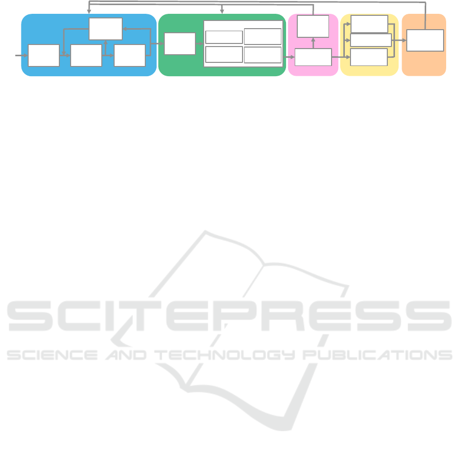
The resulting process is synthesized in figure 1.
2.1 Design Stage
The design stage mainly encompasses context analy-
sis, dialogue design, and user interface design. More-
over, formative evaluations can help to validate these
designs (Wechsung, 2014). The synthesis of the de-
sign process is detailed in figure 1.
2.1.1 Context Analysis
In the field of MIBS, the adaptation to contextual in-
formation is essential when connected devices may
be mobile or dynamically included in an interaction
chain. Therefore, the first step is usually for HCI de-
signers to analyze and define the contextual informa-
tion that will impact the system design including the
adaptation process (Pruvost, 2013). There is no single
2
https://www.w3.org/UI/
3
https://www.justice.gov/archive/jmd/irm/lifecycle/
ch1.htm
Interactive Multimodal System Characterization in the Internet of Things Context
143
Interne Orange
Context
analysis
Dialogue
modeling
UI
modeling
Design
evaluation
Software
modeling
Device
driver
Interpretation
component
Presentation
component
Dialog
component
Implementation
Components
assembly
Usability
issue
detection
integration
development
design
Device
positioning
Software setup
MIBS
configuration
User
experience
analysis
deployment
execution
Figure 1: Overview of the synthesized process to provide MIBS from requirement specifications to execution. The gray loops
represent the possibility from the integration and execution stage to impact the previous stages.
way to represent the context, but there are important
classes of concepts in MIBS.
Device models as included in the ATRACO
ontologies (Goumopoulos, 2016) are essential for
quickly defining the capabilities of connected devices
and simplify their associations with the system. En-
vironmental information is not required for all ser-
vices, but is essential for localized interactions. In
the design process of Lemmel
¨
a et al. for multi-
modal systems with mobile devices (Lemmel
¨
a et al.,
2008), designers define the impact of possible envi-
ronments on the users’ perceptual and cognitive abil-
ities. In addition, designers and architects could work
together to model physical environments, as proposed
by Pittarello et al. (Pittarello and Celentano, 2007).
The situational context should also be defined in their
approach. It could represent, among other things, the
proximity between users. This specific situational in-
formation could be used to consider nearby persons
in automatic adaptation processes or the shared as-
pect of IoT systems. The content of each context cate-
gory could be decided based on observations of target
audience’ behaviors, from the designers’ experiences,
or user experiments with prototypes (see sections 2.3
and 2.5).
In the meeting room booking service, to let the
choice between voice and gesture commands with the
connected microphones and smartphones, designers
could represent the connected microphones as devices
that can provide VUI and smartphones as GUI and
VUI providers. Moreover, pointing gestures to select
rooms require a representation of the environment,
and the smartphones positions and rotations relative
to it. Alternatively, the crowdedness situation of the
hall could be considered.
2.1.2 Dialogue Design
Once all the contextual information is modeled, de-
signers can define the dialogue. They have access
to the requirements and the contextual information
to describe the interaction tasks the users could per-
form, as well as their sequencing. Methods to define
interaction tasks include user walkthrough from ob-
servation, storyboarding (Lemmel
¨
a et al., 2008) or or
the participation of domain expert in the design (Bar-
ricelli et al., 2009). The UIs must be abstracted in
the task representation, as it is impossible to antic-
ipate which connected devices will be used in the
MIBS context. For instance, in the CAMELEON ref-
erence framework (Calvary et al., 2003) interaction
tasks models are defined without specifying any in-
formation about the UI.
In our example, designers could represent the
room booking service dialogue in four successive in-
teraction tasks: trigger the service to start interacting,
select the room, express the need to book the room,
and confirm the result. The second and third tasks
can be realized in any order, but both are required to
proceed to the last one.
2.1.3 User Interface Design
Once the dialogue model is designed, the correspond-
ing UIs could be defined. However, the exact UIs end-
users will interact with are not known at design time.
Thus, the existing approaches in the literature propose
several solutions to encompass this issue. Designers
could define the different UIs that may be used and
select the preferred one during deployment or execu-
tion. Alternatively, they could design elementary UI
elements that can be combined with a UI generation
process, like the ”Comet” paradigm (Calvary et al.,
2005) for GUI.
Four types of devices can provide UI in our room
booking service: the connected displays, the speak-
ers, and the users’ smartphones and smartwatches.
Designers could draw what would be the elementary
GUI corresponding to each task. They could also de-
fine the voice commands to inform the user to initiate
the interaction, select a room, or confirm the success
of the booking process.
2.1.4 Design Evaluation
The modeled dialogue and its UIs theoretically meet
the requirements. However, it is likely that the pro-
duced designs do not match the actual users’ needs.
As a first step, designers could detect flaws in the di-
alogue model. Then, they can assess the consistency
HUCAPP 2022 - 6th International Conference on Human Computer Interaction Theory and Applications
144

of the models with respect to the initial requirements.
Some rules and metrics could be used to predict
flaws in the dialogue models with analytical meth-
ods such as interaction path analysis (Bernhaupt et al.,
2008) or multimodal UI viability (Chang et al., 2019).
In a survey, Abdulwakel and Nabil (Abdulwakel and
nabil, 2021) proposed a classification of IoT-based
services conflicts with an a priori conflicts detection
method. This method could be used to evaluate UI
adaptation based on rules.
To check that the dialogue and UIs models are
consistent with the initial requirements, Oviatt and
Cohen (Oviatt and Cohen, 2015) suggest that design-
ers should experiment on these models with low fi-
delity prototypes. It could be with cognitive walk-
through or guidelines review on the designed system,
as presented by Bernhaupt et al. (Bernhaupt et al.,
2008). MIBS compatible guidelines could be rec-
ommendations such as those for adaptive multimodal
mobile input design in (Dumas et al., 2013), or stan-
dards in the industry like the ISO norms. Once the
designs are considered satisfactory, they are ready for
implementation.
In our previously described use case, designers
could assess the aforementioned tasks by starting with
the room selection task or the booking order task to
find what would be the most suitable based on the se-
lected modalities or context. Then, end-users could
experiment on the room booking service models. De-
signers could provide multiple drawn GUIs and audio
files, and the end-users could follow scenarios while
following the drawings and the audio tracks. After the
experimentation, the end-users could fill out usability
questionnaires or any other type of feedback.
2.2 Development Stage
Following the design stage, the development stage
consists in defining the software components and im-
plementing them. The preferred architecture in MIBS
is the components-oriented one for its high adaptation
capabilities (Avouac et al., 2011).
2.2.1 Software Components Modeling
From the UIs and the dialogue models, developers can
define the components necessary for building interac-
tion chains. There are different approaches to cate-
gorize these components, and each provides model-
ing languages to define the components’ inputs and
outputs interfaces, as well as their features. These
components could follow the canonical representa-
tion as in DynaMo (Avouac et al., 2011), but this
isn’t the sole approach for MIBS. For instance, in
DAME (Pruvost, 2013), interaction chains include
media controller components that abstract the inter-
action capabilities of devices or set of devices, and
language controller components that act as a bridge
between these device-specific components and the
device-independent dialogue components.
Developers frequently use off-the-shelf software
programs when working with IoT ecosystems from
various vendors, and for the modality-specific inter-
pretation algorithms. Thus, rigid components defini-
tions could complicate the work of developers when
they want to include these software programs. This is
one of the reasons Cronel et al. (Cronel et al., 2019)
consider a tailoring process before implementing the
necessary components. The other option is to not dif-
ferentiate between components, with weaker develop-
ment support as a trade-off.
In the room booking service, the VUI providers
and the presence sensors in each room could have
their own components providing input data, and could
depend on the devices API for the implementation. A
fusion component could use user location and com-
mands to infer user needs in our use case. Moreover,
all four interaction tasks of the dialogue could be in-
cluded in a unique component.
2.2.2 Software Components Development
The next task for developers is to implement the com-
ponents from their designs. Components are usually
implemented in the same development environment,
but the toolkit may be different according to their
proximity to devices or interaction techniques.
Indeed, in the canonical representation, input and
output modalities components are implemented with
manufacturers’ APIs to communicate with the as-
sociated devices while following standard APIs on
the MIBS side. Therefore, developers mainly need
knowledge about IoT characteristics. If we take the
fusion component in our use case as an example, the
developers need to implement a tracking algorithm
from the user detection, and when a command is re-
ceived, send it with the tracked information. The
tracking method needs to be tailored to the presence
sensors data to avoid false positives and negatives.
The software components that correspond to the
dialogue model are usually the center of the literature
propositions. The dialogue could be implemented
as a set of components included in the composition
chain as in Openinterface (Lawson et al., 2009) or
DAME (Pruvost, 2013). It could also be the part of
the system that manages the composition itself, as in
DynaMo (Avouac et al., 2011).
The interpretation and presentation components
between the devices and the dialogue are the least
consensual in their exact definitions. For instance,
Interactive Multimodal System Characterization in the Internet of Things Context
145

interpretation components are separated from fusion
components in SIAM-DP (Neßelrath, 2015). The for-
mer components transform the data from the devices
into a semantic representation, whereas the latter ones
only fuse the semantic information. The DAME (Pru-
vost, 2013) approach represents with the same com-
ponents input and output capabilities. Thus, it consid-
ers the potential dependency between input and out-
put modality.
2.3 Integration Stage
At the integration stage, all the necessary software
components have been produced, and developers and
interaction designers can assemble fully functional
prototypes with them. This assembly task is nec-
essary for the static approaches, where applications
are adapted manually between sessions according to
the target context. However, dynamic approaches
(i.e. runtime adaptation to context) can provide pro-
totypes without manually assembling components, as
it will be done automatically. In either case, the pro-
totypes can then be assessed by UX designers and er-
gonomists in realistic environments.
Partial prototypes could also be created to per-
form these evaluations, or to prospect future interac-
tion techniques or modalities unavailable at the mo-
ment (Taib and Ruiz, 2007). Besides, Working with
partial prototypes reduces the reaction time to correct
components issues, thereby reducing their production
costs (Oviatt and Cohen, 2015; Vilimek, 2008). Fi-
nally, once a prototype is satisfactory, it can be pack-
aged and provided to administrators for deployment.
2.3.1 Components Assembly
Assembly refers to the composition of the devel-
oped software components to produce the interaction
chains that provide the services according to the ap-
plication specifications. The assembly process could
be assigned to interaction designers or developers de-
pending on the simplicity of the selected tool, as de-
tailed in section 3.2.
In the room booking service, designers could de-
cide to test the room selection interaction task with a
smartphone. To do so, they connect a smartphone-
associated component, an interpretation component
for speech recognition, the previously presented fu-
sion component, a dialogue component representing
the service, and a presentation component to trans-
form a message into an elementary GUI element.
Then, they assemble them. For Instance, the presence
sensors and speech detected in each room are linked
to the fusion component.
2.3.2 Usability Issue Detection
Designers and ergonomists could assess the proto-
types to detect flaws in the MIBS (i.e. issues in the in-
teraction chains, components implementation, or de-
sign models), patterns in users’ behaviors, or if the
prototypes still comply with the guidelines presented
in section 2.1.4. Thus, it could require changes in the
previous stages. This technique doesn’t provide ex-
haustive and complete analyses (Pruvost, 2013) but is
the closest observation of the system anticipated use
so far. Prototype experiments can be separated be-
tween model-based and user-based ones.
The first type is based on the system simula-
tion with modeled users and environments (Bernhaupt
et al., 2008; Pruvost, 2013). Compared to the other
approaches, simulations are cheap, harmless, flexible,
and could create situations and environments diffi-
cult or even impossible to reproduce in reality (Pru-
vost, 2013; Oviatt and Cohen, 2015). However, they
are simplified, if not distorted, versions of their real-
world counterparts, reducing the validity of the results
and introducing biases. Moreover, simulations with-
out real end-users lack the limit testing only they can
do (Pruvost, 2013).
The second type consists of user experiments.
Designers could assess beforehand the prototypes to
check if they are still compliant with the guidelines
considered in the section 2.1.4. The advantage is
to evaluate the components composition alternatives
in partially or fully functional prototypes (Vilimek,
2008; Bernhaupt et al., 2008) according to trusted
standards and the designers’ experience. Then, real
users could experiment with the prototypes. The
participants’ behaviors are analyzed (Vilimek, 2008;
Oviatt and Cohen, 2015) and their experience feed-
backs are recorded (Bernhaupt et al., 2008), as in the
rapid prototyping process of Lemmel
¨
a et al. (Lem-
mel
¨
a et al., 2008). With a complete prototype in the
hands of real users, these experiments are the closest
to the ground truth, but their costs, limitations to envi-
ronments the experimenters can create, and their con-
figurations rigidity is their downsides (Vilimek, 2008;
Oviatt and Cohen, 2015).
In the room booking service, it would be during
these experiments that designers could face practical
issues. For example, rays of light in the afternoon
could make the display of one of the envisioned meet-
ing rooms impossible to use.
It should be noted that simulation is sometimes
followed by experiments with users to get the best
of both worlds (Kirisci et al., 2011). Indeed, starting
with simulations reduces the cost and the time neces-
sary for issues that experts can detect, and then exper-
HUCAPP 2022 - 6th International Conference on Human Computer Interaction Theory and Applications
146

iments can be performed to detect issues only end-
users interactions analysis can find. However, this
doesn’t reduce the cost, and the duration is still the
addition of the two duration necessary for these ex-
periments.
2.4 Deployment Stage
Deployment revolves around the installation of the in-
teractive system in the execution environment by ad-
ministrators, who could be the users of the services
(e.g. home services) or IT managers (e.g. offices
environments). They must manage the devices’ spa-
tial layout, handle the MIBS configuration, and con-
nect the connected devices to the MIBS. The order in
which the previous three tasks are performed is arbi-
trary and could change whether the system can adapt
to a change in devices position, or if there is an order
between the system and the devices’ startup.
2.4.1 Device Positioning
As connected devices are more and more common in
our surroundings, they are usually already installed.
However, the administrators could need more devices
for a particular service. They could also move some
of the installed ones. This implies a careful placement
of those devices, as they need to blend in the user
surroundings (Burzagli et al., 2007). Administrators
could follow instructions from the previous stages or
generic installation recommendations. However, mul-
tiple trials and errors may be required before a satis-
factory positioning is achieved. Moreover, the devices
need to be hidden in ubiquitous environments, so rela-
tive positioning between the devices and the environ-
ment geometry is also important.
2.4.2 MIBS Configuration Setup
The environment geometry, the characteristics of the
available interaction devices, and the network qual-
ity are among the concerns in MIBS. These contex-
tual considerations are only known at the deployment
stage. Thus, administrators could configure the sys-
tem based on the context of use before starting a
session. They could customize the system accord-
ing to the current context as proposed by Burzagli
et al. in their requirements (Burzagli et al., 2007).
For instance, connected devices with their locations
in the environment could be registered in the sys-
tem. For static approaches, they could also select
the interaction chains with the available devices, as
in ICARE (Bouchet et al., 2004).
In our use case, we consider that the IT managers
select the devices. Thus, they could select an interac-
tion chain from those recommended by the designers.
For instance, they could select the interaction chain
that uses microphones and presence sensors, and then
associate the connected devices in each meeting room
with the service.
2.4.3 Device Software Setup
Finally, the connected devices must be started, config-
ured, and connected to the system depending on the
architecture discovery and registration capabilities.
Regarding the communication process, Rodriguez
et al. (Rodriguez and Moissinac, 2017) explain that
there is no single protocol in the IoT, as each ven-
dor usually has its own network ecosystem. As a re-
sult, devices deployment is generally not addressed
in MIBS-related literature, and they resort to ad hoc
solutions. Nevertheless, they propose in their work a
model of modality component and a process for dis-
covery and registration that could lead to a consen-
sus in the IoT community. Administrators could also
specify here the location of the devices if they have
no way of knowing their location in the environment.
In our use case, smartphones are accessible via
Wifi or mobile networks, while presence sensors
might only be available with Z-wave
4
or other low-
level protocols and technologies. Thus, IT man-
agers could use an IoT platform such as OpenHAB
5
to allow the MIBS to communicate with all devices
through a unique network and protocol.
2.5 Execution Stage
Once the MIBS is running, end-users can finally in-
teract with it. However, the MIBS can be further
evaluated with the extensive data available at this
stage to identify user preferences or dislikes regarding
the interactive system. It should be mentioned that
the MIBS maintenance remains a challenge (Chang
et al., 2019): the IoT is composed of various networks
evolving at different rates, and each device in these
networks has its own hardware and software lifespan.
2.5.1 User Experience Analysis
The evaluation can be separated into user observation
and user feedback. For the latter, techniques such
as user improvement propositions (Barricelli et al.,
2009) or questionnaires (Bernhaupt et al., 2008) could
be used to detect defects that were not previously
detected. User preferences (Bernhaupt et al., 2008)
4
https://www.z-wave.com/
5
https://www.openhab.org/
Interactive Multimodal System Characterization in the Internet of Things Context
147

could also be detected, for instance with log files anal-
ysis on field observations.
These evaluation methods are similar to the user-
based experiments in the integration stage, but the
lack of controlled settings, the larger number of users,
and the potentially greater diversity of environments
lead to more in-depth insights on the system (Bern-
haupt et al., 2008; Wechsung, 2014) at the cost of
a higher cost and the product reputation (Oviatt and
Cohen, 2015; Carlsson and Schiele, 2007). More-
over, the interaction devices could be hidden in MIBS.
Therefore users are less aware of how the system col-
lects data about them and could be less willing to
share their data.
In our use case, the IT manager could be the
only one to have access to users’ usage rate of the
room booking service. Furthermore, the data could be
anonymized to ensure user ownership over the data.
The result of the data analysis could be taken into
account at any stage. Indeed, it could lead to new
requirements, thus starting a whole new cycle. Im-
plementation issues could be discovered when facing
specific situations. New interaction chains could be
inferred from users’ feedback, while administrators
could change some parameters to better tailor the sys-
tem to the users’ needs.
3 TOOLS IN LITERATURE
Completing the life cycle of MIBS requires multi-
ple stages, however the tasks associated with each
stage may require advanced design and development
knowledge, can be time-consuming, and sometimes
repetitive. Therefore, dedicated tools are needed to
ease the work of the different stakeholders.
In this section we present the software tools that
have been used to create multimodal systems and are
compatible with IoT-based systems, according to the
tasks they help to accomplish at each stage.
3.1 Design Tools
As detailed in section 2.1, the MIBS design stage con-
sists of the definition of the contextual information,
the dialogue model, and the UIs. Design tools are less
concerned with the IoT aspect of MIBS. Indeed, the
only specific requirements are to separate the dialogue
from the devices, and to provide UIs for a larger set
of interactive devices.
As presented in section 2.1.1, there are differ-
ent classes of contextual information. Therefore the
representation should be flexible enough to support
the diversity of contexts. Ontology is said to be the
best data representation in MIBS for its extensibil-
ity and structure that eases the context reasoning pro-
cess (Pruvost, 2013). For instance, the environment
geometry could be described as an ontology, as in
(Pittarello and Celentano, 2007). Tools such as the
ontology editor Prot
´
eg
´
e
6
provide easy management
of generic standard ontologies. Prot
´
eg
´
e in particular
was used to represent knowledge bases in multimodal
systems (Mendonc¸a et al., 2009; Pruvost, 2013) and
supports the W3C language standard
7
. However, Pru-
vost (Pruvost, 2013) asserts that this tool is complex
to learn and too permissive. Thus, he has built on its
API the ”Describe” tool (Pruvost, 2013) to simplify
the edition of ontologies, and to forbid the edition of
their architecture core ontologies. Ontologies have
some shortcomings compared to other context repre-
sentations (Perttunen et al., 2009). For instance, it is
relatively easy to create inconsistency in the context
representation, and consistency checks are expensive.
Once the context is defined, numerous tools are
proposed to model the dialogue tasks (Nigay et al.,
2015). For example, CTTe (Mori et al., 2002) helps
interaction designers to specify the dialogue as inter-
action tasks based on a task tree representation. This
tool also offers low fidelity prototyping (Oviatt and
Cohen, 2015) functionality to check if the dynamic
functioning of the task model corresponds to the inter-
action requirements. The complementarity between
the room selection task and the booking order task in
the room booking service could easily be described as
subtasks linked by a temporal operator.
The designed dialogue could be analyzed to pre-
dict its flaws. Just as CTTe and IMBuilder have sim-
ulation capabilities, two other tools can help to ease
the system analysis. Silva et al. (Silva et al., 2013)
use Petshop (Navarre et al., 2009) and Colored Petri-
net tools (Jensen et al., 2007) for formal verification
of the interaction paths, and MIGTool (Brajnik and
Harper, 2016) helps to transform scenario specifica-
tions into interaction paths to analyze and compare
abstract interaction models according to metrics such
as UI flexibility or consistency.
With the tasks defined and validated, designers
can model the UIs. UI design could be separated be-
tween graphical and non-graphical device-dependent
representations. Graphical user interfaces (Pruvost,
2013; Neßelrath, 2015) in multimodal systems are de-
signed with UI description languages and associated
tools. For web-based interfaces, tools such as Boot-
strap
8
support HTML5 and CSS edition, and various
6
https://protege.stanford.edu/
7
https://www.w3.org/TR/owl2-overview/
8
https://getbootstrap.com/
HUCAPP 2022 - 6th International Conference on Human Computer Interaction Theory and Applications
148

tools such as the markup validation service
9
comple-
ment the editors with useful features. Apple Inter-
face Builder
10
and Sketch
11
are tools to create UIs
for the Apple ecosystem. Grundy and Yang (Grundy
and Yang, 2003) developed an editor in which UI
designers can model graphical interfaces in multi-
ple layout views and custom-made tags for adapta-
tion. TERESA (Patern
`
o et al., 2008) allows construct-
ing UIs from a task model composed of graphical
and vocal elements. Alternatively, the graphical tool
MOSTe (Rousseau et al., 2005; Rousseau et al., 2006)
helps to specify any interaction components (i.e. the
device components) in an abstract representation, and
even provides an editor to define rules for dynamic
selection of UIs. This rule-based interface selection
strategy is also present in the Behave tool (Pruvost,
2013) or in the authoring environment of Ghiani et
al. (Ghiani et al., 2015). For VUIs, the interface is not
based on the spatial distribution of elementary com-
ponents, but the succession of temporal dialogue ele-
ments. Therefore, it could be considered as a part of
the dialogue model, or as a separate entity. In the lat-
ter case, many commercialized tools could be used.
For instance, VUIs could be represented as decision
diagrams with the graphical tool Voiceflow
12
. In addi-
tion, tools such as BotSociety
13
could help designers
to preview VUIs. Other UIs are less standardized than
the previous two. Therefore, the first tools were asso-
ciated with a limited set of devices, or required techni-
cal knowledge (Moussette, 2007). However, the field
has matured since then, and tools that are easy-to-
use and non-technical start to emerge. For instance,
the process to design haptic UI is simplified by the
graphical tool Feelix (van Oosterhout et al., 2020): it
requires no prior technical knowledge to design UIs
and includes an intuitive sketch editor.
From these models, designers could experiment
the system with users. They could use the SIHMM
simulator (Bodic et al., 2004) to observe virtual users
interacting with simulated mobile devices in a mod-
eled environment. In this tool, designers have to
model multimodal properties of devices, physical and
social perturbations environment entities could gen-
erate, the scenario to follow, and the user model dic-
tating their interaction preferences. In the same way,
MuMoWOz (Ardito et al., 2009) is a tool to evalu-
ate design choices with Wizard of Oz experiments.
However, designers have to define the concrete con-
tent to provide to users during experiments, and this
9
https://validator.w3.org/
10
https://developer.apple.com/xcode/interface-builder/
11
https://www.sketch.com/
12
https://www.voiceflow.com/
13
https://botsociety.io/
tool only covers mobile multimodal systems. An in-
teraction designer can also evaluate the system with-
out modeling everything beforehand, as in the tool
CrossWeaver (Sinha and Landay, 2003). Here, inter-
action designers create a storyboard by defining the
system state as drawings, possible transitions accord-
ing to user inputs, and the system feedbacks to users.
Then, end-user experiments are performed to produce
logs that designers can view and replay.
3.2 Development Tools
As detailed in Section 2.2.1, the process to define the
components inputs, outputs, and features prior to the
actual implementation helps to clarify the purpose of
each component. Therefore, it ensures the necessity
of each component and providing better documenta-
tion. System designers could use SKEMMI (Lawson
et al., 2009) to describe components with a simplified
component representation, whereas developers could
work on these components on their specific level. The
possibility to work on the same components on dif-
ferent views for system designers and developers is
beneficial for cooperation, but, to our knowledge, this
feature is only present in this software tool.
To develop the device drivers, services, presenta-
tion, and interpretation software components, exist-
ing approaches often offer the same editor and require
to follow code patterns to match their component
model and functionalities. In SIAM-DP (Neßelrath,
2015), they propose plugins for Eclipse to help devel-
opers generate code templates, visualize the dialogue
flow and preview the GUI. Identically, the AsTeRICS
toolkit
14
also provides templates with Eclipse exten-
sions to implement compatible components. Then, it
is up to the developers to fill the component patterns
with the necessary code, using service API and SDKs.
Before implementing the dialogue components,
developers could transform the model into a machine-
readable dialogue. To do this, developers have
access to various interactive system editors. IM-
Builder (Bourguet, 2002), FSM translator (Chang and
Bourguet, 2008) and MyUI editor (Peissner et al.,
2011) are some of these tools that permit the imple-
mentation of the dialogue as a finite state machine
(FSM). Petshop (Navarre et al., 2009) provides the
same service, but with a Petri-net representation.
3.3 Integration Tools
At this stage, developers and designers can use the de-
veloped components in integration tools to create pro-
totypes. To assemble software components in interac-
14
https://www.asterics.eu/
Interactive Multimodal System Characterization in the Internet of Things Context
149

tion chains, most tools adopt a graphical representa-
tion of components, and the components can be linked
to each other through their interfaces. ICON (Drag-
icevic and Fekete, 2001) is a graphical editor that
helps to create interaction chains. However, it re-
quires a good understanding of its components rep-
resentation and implementation, and can therefore be
difficult to master quickly. ICARE (Bouchet et al.,
2004) improves on this concept and enables creation
without the need of extensive knowledge thanks to the
CARE paradigm representation (Coutaz et al., 1995).
Indeed, interaction chains are presented here from the
end-user perspective, which is more intuitive to work
with than abstract implementation variables such as
cursors x or y positions. ACS
15
is another graphi-
cal tool for assistance services development similar to
SKEMMI (Lawson et al., 2009). In addition, ACS
provides a GUI editor based on the component in-
stantiated. The system construction workbench of
Shen et al. (Shen et al., 2011) also enables develop-
ers to define interaction chains with a debugging tool.
However, its publish-subscribe architecture permits
the complex and dynamic association of components.
Finally, the prototyping tool in (Seiger et al., 2015)
differs from the previous tools. First, it enables devel-
opers to modify the composition of the components
during execution. Second, it integrates the attributes
of the components in their graphical representation
which eases the configuration process. However, the
publish-subscribe architecture is lost here. The level
of expertise to use these tools isn’t high: it only con-
sists in graphically adding and linking components.
From the developed prototypes, designers and er-
gonomists could assess their usability before deliver-
ing the best one to the administrators. There are mul-
tiple methods to assess these multimodal prototypes
(see section 2.3), but software tools are not used for
methods other than simulation. Indeed, the designers
rely on their personal experience for the guidelines
compliance assessment. For the users’ experiments,
designers only need to observe users and collect their
feedback with questionnaires.
For the simulation method, only one tool was
found to assess MIBS prototypes. Pruvost (Pru-
vost, 2013) created the ”Simulate” tool that a de-
signer could use to simulate the system behavior in
a schematic representation of the environment. This
representation is easy to create but is far from the real
world condition.
The deployment and execution tools (see sections
3.4 and 3.5) can also be used in the integration phase
during field or laboratory experiments.
15
https://www.asterics.eu/manuals/ACS/
3.4 Deployment Tools
The final prototype is sent to the administrator for de-
ployment. Some processes present the deployment
phase as being simple as starting a software program.
One example is the ARE tool
16
that provides a simple
menu to handle the system execution. Even if there
are systems that dynamically select their interaction
devices, most approaches still need an administrator
to place the hardware, start and configure the interac-
tive system and the devices. To do this, administrators
could be assisted in their tasks.
The assembly tools presented in the integration
stage (e.g. ICON (Dragicevic and Fekete, 2001))
could also be used here. However, users need knowl-
edge about multimodality and data representation to
be able to use them. Moreover, they still need to know
how to install the devices in the environment, as no
spatial information is provided.
Finally, the MIBO Interactive Editor (Peters et al.,
2016) offers two features for an administrator. This
graphical programming tool enables instantiating
simple services rapidly without expertise. It even pro-
vides a debugging tool to determine if the defined ser-
vices conflict with each other. Nevertheless, it doesn’t
handle multimodal output (i.e. it only controls con-
nected devices), nor does it provides spatial installa-
tion guidelines.
Therefore, the existing tools provide some support
to the deployment stage but don’t perform all the tasks
identified in the section 2.4: the tasks of placing de-
vices and configuring their software programs are not
addressed.
3.5 Execution Tools
Once the system is started, administrators and ven-
dors might monitor users to detect behavior patterns,
preferences, or undetected flaws until then. For exam-
ple, in the MMWA authoring environment (Neto and
de Mattos Fortes, 2010), designers can access the user
interaction log. Augmented Reality monitoring tools
such as presented by Lacoche et al. (Lacoche et al.,
2019) could also be adapted to multimodal systems.
Indeed, immersion could help to better understand the
state of the system. It is a common practice nowadays
to monitor users to hasten hotfix patches development
with network updates, but the privacy and security re-
quirements depend on the service and target audience.
Thus it seems that runtime monitoring is usually re-
stricted to the prototyping evaluation strategy in the
integration phase.
16
https://www.asterics.eu/get-started/Overview.html#
are
HUCAPP 2022 - 6th International Conference on Human Computer Interaction Theory and Applications
150

Table 1: This table summarizes what are the tasks in the SLDC of MIBS that aren’t well supported by software tools. ”X”,
”?” and ”X” represent the tasks that are well supported, could be improved or not supported (respectively).
Design Development Integration Deployment Execution
Context analysis X Software modeling X Components assembly X Device positioning X User experience analysis ?
Dialogue modeling X Components implementation X Usability issue detection ? Software setup X
UI modeling ? MIBS configuration X
Design evaluation X
4 DISCUSSION
From our analysis of the tasks and tools for MIBS
development, we can see that some aspects are still
not sufficiently addressed. Below we discuss the tasks
that could be better supported.
Devices representations, which define their inter-
action capabilities, and their corresponding compo-
nents are properly handled when they provide graph-
ical or vocal modalities, but other modalities, which
are numerous in IoT systems, are considered more as
providers or consumers of events without further sup-
port. Works such as the DOG ontology (Bonino and
Corno, 2008) could be used as a basis to provide stan-
dard representations of connected devices, and thus
could improve the tools support.
System testing in the integration phase still lacks a
tool to assess a multimodal system in a realistic sim-
ulation with real users. Indeed, field and laborato-
ries experiments are difficult and costly to perform,
but they guarantee results close to the ground truth.
Simulation is a good strategy to quickly test several
configuration chains, but existing tools rely on mod-
eled users, so the results are more likely to be bi-
ased. Simulation with real users could bring the reli-
ability of laboratory experiments with the ease of use
of the simulation approach, and Virtual Reality (VR)
could be a promising technology in this aspect. Works
on simulated interactive systems such as the VUMS
project (Peissner et al., 2011) or the Augmented Re-
ality (AR) application pipeline in (Soedji et al., 2020)
could provide a basis to assess user interactions in
MIBS simulations.
Deployment tools only consider the software con-
figuration, but they lack a mean to help the admin-
istrator place the interaction devices without rely-
ing on trial and error. Perhaps a companion system
such as the one presented by Bercher et al. (Bercher
et al., 2018) could help administrators during installa-
tion: localized visual cues in a simulated environment
could lead to a better understanding of the positioning
to do. This also means that we need a method to de-
scribe beforehand the real environment and its ability
to host the desired services. The environment capture
and device configuration in AR proposed by Soedji et
al. (Soedji et al., 2020) could solve this issue. There-
fore, an augmented reality-based companion system
could fill the gap in the deployment stage.
Finally, there are only a few supports for multi-
modal systems monitoring, which could be useful for
multimodal services. Indeed, some multimodal ap-
plications could use online services or IoT systems
accessible from everywhere. Thus online monitoring
tools could be used for maintenance in case of service
outage or IoT malfunction, in addition to application
flaw detection. The Smart Space Solution of Soft-
engi
17
, which eases IoT monitoring using AR tech-
nology, could be adapted to the multimodal paradigm.
5 CONCLUSION
Our identification of the tasks and software tools as-
sociated with the SDLC of multimodal systems using
connected devices as interactive mediums leads to a
proposition of the tools that could be designed to fill
the gap in the identified process. This is synthesised
in table 1.
User interfaces design other than graphical or vo-
cal ones require more standardized and easy-to-use
tools than the existing ones. The integration stage
could benefit from better simulation tools to evaluate
such environment-dependent systems without relying
on the costly laboratory or field experiments. Deploy-
ment is also not well explored, and improved instal-
lation tools could ease this part of the process. The
effort could be focused on providing tools to easily
identify and place connected devices in the environ-
ment. More intuitive monitoring tools could also be
beneficial for multimodal systems where interaction
devices are distributed.
The identified process and our analysis could
guide the creation of a framework and new tools for
future researchers in the field of multimodal interac-
tion who want to use connected devices as mediums
of interaction.
17
https://softengi.com/projects/public-sector/
smart-space-solution-for-the-softengi-office/
Interactive Multimodal System Characterization in the Internet of Things Context
151

REFERENCES
Abdulwakel, H. and nabil, e. (2021). A conflicts’ classifi-
cation for IoT-based services: a comparative survey.
PeerJ Computer Science, 7.
Ardito, C., Buono, P., Costabile, M., Lanzilotti, R., and Pic-
cinno, A. (2009). A tool for Wizard of Oz studies of
multimodal mobile systems. In HSI’09, pages 344–
347.
Avouac, P.-A., Lalanda, P., and Nigay, L. (2011). Service-
oriented autonomic multimodal interaction in a perva-
sive environment. In ICMI ’11, page 369, Alicante,
Spain. ACM Press.
Barricelli, B. R., Marcante, A., Mussio, P., Provenza, L. P.,
and Padula, M. (2009). Designing Pervasive and Mul-
timodal Interactive Systems: An Approach Built on
the Field. In Grifoni, P., editor, Multimodal Hu-
man Computer Interaction and Pervasive Services.
IGI Global.
Bercher, P., Richter, F., Honold, F., Nielsen, F., Sch
¨
ussel, F.,
Geier, T., Hoernle, T., Reuter, S., H
¨
oller, D., Behnke,
G., Dietmayer, K. C. J., Minker, W., Weber, M., and
Biundo, S. (2018). A companion-system architec-
ture for realizing individualized and situation-adaptive
user assistance. Universit
¨
at Ulm.
Bernhaupt, R., Navarre, D., Palanque, P., and Winckler,
M. (2008). Model-Based Evaluation: A New Way to
Support Usability Evaluation of Multimodal Interac-
tive Applications. In Law, E. L.-C., Hvannberg, E. T.,
and Cockton, G., editors, Maturing Usability: Qual-
ity in Software, Interaction and Value, pages 96–119.
Springer, London.
Bodic, L., De Loor, P., Calvet, G., and Kahn, J. (2004).
SIHMM: Simulateur de l’Interaction Homme Ma-
chine Multimodale. In Nigay, L., editor, IHM’04,
pages 31–34.
Bolt, R. A. (1980). “Put-that-there”: Voice and gesture at
the graphics interface. ACM SIGGRAPH Computer
Graphics, 14(3):262–270.
Bonino, D. and Corno, F. (2008). DogOnt - Ontology Mod-
eling for Intelligent Domotic Environments. In Inter-
national Semantic Web Conference, pages 790–803.
Springer.
Bouchet, J., Nigay, L., and Ganille, T. (2004). ICARE soft-
ware components for rapidly developing multimodal
interfaces. In ICMI ’04, page 251, State College, PA,
USA. ACM Press.
Bourguet, M.-L. (2002). A toolkit for creating and testing
multimodal interface designs. companion proceedings
of UIST.
Brajnik, G. and Harper, S. (2016). Measuring interaction
design before building the system: a model-based ap-
proach. In EICS’16, pages 183–193, Brussels, Bel-
gium. Association for Computing Machinery.
Bui, H. T. (2006). Multimodal dialogue management-state
of the art. CTIT Technical Report Series.
Burzagli, L., Emiliani, P. L., and Gabbanini, F. (2007). Am-
bient Intelligence and Multimodality. In Stephanidis,
C., editor, Universal Access in Human-Computer In-
teraction. Ambient Interaction, pages 33–42. Springer.
Calvary, G., Coutaz, J., D
ˆ
aassi, O., Balme, L., and De-
meure, A. (2005). Towards a New Generation of Wid-
gets for Supporting Software Plasticity: The ”Comet”.
In EHCI-DSVIS, pages 306–324. Springer.
Calvary, G., Coutaz, J., Thevenin, D., Limbourg, Q., Bouil-
lon, L., and Vanderdonckt, J. (2003). A Unifying Ref-
erence Framework for multi-target user interfaces. In-
teracting with Computers, 15(3):289–308.
Carlsson, V. and Schiele, B. (2007). Towards systematic re-
search of multimodal interfaces for non-desktop work
scenarios. In CHI ’07, pages 1715–1720. Association
for Computing Machinery, New York, USA.
Caschera, M. C., D’Ulizia, A., Ferri, F., and Grifoni, P.
(2015). Multimodal Systems: An Excursus of the
Main Research Questions. In OTM 2015 Workshops,
pages 546–558.
Chang, J. and Bourguet, M.-L. (2008). Usability Frame-
work for the Design and Evaluation of Multimodal
Interaction. In Multimodality in Mobile Computing
and Mobile Devices: Methods for Adaptable Usabil-
ity, BCS-HCI ’08, Swindon, UK.
Chang, S.-F., Hauptmann, A., Morency, L.-P., Antani, S.,
Bulterman, D., Busso, C., Chai, J., Hirschberg, J.,
Jain, R., Mayer-Patel, K., Meth, R., Mooney, R.,
Nahrstedt, K., Narayanan, S., Natarajan, P., Oviatt,
S., Prabhakaran, B., Smeulders, A., Sundaram, H.,
Zhang, Z., and Zhou, M. (2019). Report of 2017 NSF
Workshop on Multimedia Challenges, Opportunities
and Research Roadmaps. arXiv:1908.02308 [cs].
Coutaz, J., Nigay, L., Salber, D., Blandford, A., May, J.,
and Young, R. M. (1995). Four Easy Pieces for As-
sessing the Usability of Multimodal Interaction: The
Care Properties. In Human—Computer Interaction,
pages 115–120. Springer US, Boston, MA.
Cronel, M., Dumas, B., Palanque, P., and Canny, A.
(2019). MIODMIT: A Generic Architecture for Dy-
namic Multimodal Interactive Systems. In Bogdan,
C., Kuusinen, K., L
´
arusd
´
ottir, M. K., Palanque, P., and
Winckler, M., editors, Human-Centered Software En-
gineering, pages 109–129, Cham. Springer.
Dragicevic, P. and Fekete, J.-D. (2001). Input Device Se-
lection and Interaction Configuration with ICON. In
Blandford, A., Vanderdonckt, J., and Gray, P., editors,
People and Computers XV—Interaction without Fron-
tiers, pages 543–558. Springer, London.
Dumas, B., Sol
´
orzano, M., and Signer, B. (2013). Design
Guidelines for Adaptive Multimodal Mobile Input So-
lutions. In Mobile HCI’13.
Ferri, F., Grifoni, P., Caschera, M. C., D’Andrea, A.,
D’Ulizia, A., and Guzzo, T. (2018). The HMI digi-
tal ecosystem: challenges and possible solutions. In
MEDES’18, pages 157–164, Tokyo, Japan. Associa-
tion for Computing Machinery.
Ghiani, G., Manca, M., and Patern
`
o, F. (2015). Authoring
context-dependent cross-device user interfaces based
on trigger/action rules. In MUM’15, pages 313–322,
Linz, Austria. Association for Computing Machinery.
Goumopoulos, C. (2016). A Middleware Architecture for
Ambient Adaptive Systems, pages 1–35. Springer.
Grundy, J. and Yang, B. (2003). An environment for de-
veloping adaptive, multi-device user interfaces. In
HUCAPP 2022 - 6th International Conference on Human Computer Interaction Theory and Applications
152

AUIC, pages 47–56, Adelaide, Australia. Australian
Computer Society, Inc.
Jensen, K., Kristensen, L. M., and Wells, L. (2007).
Coloured Petri Nets and CPN Tools for modelling and
validation of concurrent systems. STTT, 9(3):213–
254.
Kirisci, P. T., Thoben, K.-D., Klein, P., and Modzelewski,
M. (2011). Supporting Inclusive Product Design With
Virtual User Models at the Early Stages of Product
Development. ICED 11.
Lacoche, J., Le Chenechal, M., Villain, E., and Foulonneau,
A. (2019). Model and Tools for Integrating IoT into
Mixed Reality Environments: Towards a Virtual-Real
Seamless Continuum. In ICAT-EGVE, Tokyo, Japan.
Lawson, J.-Y., Al-Akkad, A.-A., Vanderdonckt, J., and
Macq, B. (2009). An open source workbench for
prototyping multimodal interactions based on off-the-
shelf heterogeneous components. In EICS’09, pages
245–254.
Lemmel
¨
a, S., Vetek, A., M
¨
akel
¨
a, K., and Trendafilov, D.
(2008). Designing and evaluating multimodal interac-
tion for mobile contexts. In ICMI’08, Chania, Crete,
Greece. Association for Computing Machinery.
Mendonc¸a, H., Lawson, J.-Y. L., Vybornova, O., Macq,
B., and Vanderdonckt, J. (2009). A fusion frame-
work for multimodal interactive applications. In
ICMI-MLMI’09, pages 161–168, Cambridge, Mas-
sachusetts, USA. Association for Computing Machin-
ery.
Mori, G., Patern
`
o, F., and Santoro, C. (2002). CTTE: Sup-
port for Developing and Analyzing Task Models for
Interactive System Design. IEEE Trans. Software Eng.
Moussette, C. (2007). Tangible interaction toolkits for de-
signers. In SIDeR07.
Navarre, D., Palanque, P., Ladry, J.-F., and Barboni, E.
(2009). ICOs: A model-based user interface descrip-
tion technique dedicated to interactive systems ad-
dressing usability, reliability and scalability. TOCHI.
Neßelrath, R. (2015). SiAM-dp. PhD thesis, Saarland Uni-
versity.
Neto, A. T. and de Mattos Fortes, R. P. (2010). Improv-
ing multimodal interaction design with the MMWA
authoring environment. In SIGDOC ’10. Association
for Computing Machinery, New York, USA.
Nigay, L., Laurillau, Y., and Jourde, F. (2015). Description
of tasks with multi-user multimodal interactive sys-
tems: existing notations. JIPS.
Oviatt, S. and Cohen, P. R. (2015). The Paradigm Shift to
Multimodality in Contemporary Computer Interfaces.
Synthesis Lectures on Human-Centered Informatics,
8(3):1–243. Morgan & Claypool Publishers.
Patern
`
o, F., Santoro, C., M
¨
antyj
¨
arvi, J., Mori, G., and San-
sone, S. (2008). Authoring pervasive multimodal user
interfaces. IJWET.
Peissner, M., Biswas, P., Mohamad, Y., Jung, C., Wolf, P.,
Gonz
´
alez, M. F., and Kaklanis, N. (2011). Interim
Report on VUMS cluster standardisation.
Perttunen, M., Riekki, J., Oulu, I., Lassila, O., and Services,
N. (2009). Context Representation and Reasoning in
Pervasive Computing: a Review. IJMUE’2009.
Peters, S., Johanssen, J. O., and Bruegge, B. (2016). An
IDE for multimodal controls in smart buildings. In
ICMI’16, pages 61–65, Tokyo, Japan. Association for
Computing Machinery.
Pittarello, F. and Celentano, A. (2007). Deployment of Mul-
timodal Services: an Ontology Driven Architecture.
In ICPS’2007, pages 267–274.
Pruvost, G. (2013). Mod
´
elisation et conception d’une plate-
forme pour l’interaction multimodale distribu
´
ee en in-
telligence ambiante. phdthesis, Universit
´
e Paris Sud.
Rodriguez, B. H. and Moissinac, J.-C. (2017). Discov-
ery and Registration: Finding and Integrating Com-
ponents into Dynamic Systems. In Multimodal Inter-
action with W3C Standards, page 325. Springer.
Rousseau, C., Bellik, Y., Vernier, F., and Bazalgette, D.
(2005). Multimodal output simulation platform for
real-time military systems. In 11th HCII.
Rousseau, C., Bellik, Y., Vernier, F., and Bazalgette,
D. (2006). A framework for the intelligent multi-
modal presentation of information. Signal Processing,
86(12):3696–3713.
Seiger, R., Niebling, F., Korzetz, M., Nicolai, T., and
Schlegel, T. (2015). A framework for rapid pro-
totyping of multimodal interaction concepts. In
LMIS@EICS, volume 1380, pages 21–28.
Shen, J., Shi, W., and Pantic, M. (2011). HCIλ2 Work-
bench: A development tool for multimodal human-
computer interaction systems. In 9th FG, pages 766–
773.
Silva, J., Fayollas, C., Hamon, A., Palanque, P., Martinie,
C., and Barboni, E. (2013). Analysis of wimp and
post wimp interactive systems based on formal speci-
fication. ECEASST, 69.
Sinha, A. and Landay, J. (2003). Capturing user tests in a
multimodal, multidevice informal prototyping tool. In
ICMI’03, pages 117–124.
Soedji, B. E. B., Lacoche, J., and Villain, E. (2020). Creat-
ing AR Applications for the IOT : a New Pipeline. In
VRST ’20, Virtual Event Canada, France. ACM.
Taib, R. and Ruiz, N. (2007). Wizard of Oz for Multimodal
Interfaces Design: Deployment Considerations. In
12th HCII.
Turk, M. (2014). Multimodal interaction: A review. Pattern
Recognition Letters, 36:189–195.
van Oosterhout, A., Bruns, M., and Hoggan, E. (2020). Fa-
cilitating Flexible Force Feedback Design with Feelix.
In ICMI’20, pages 184–193, Virtual Event, Nether-
lands. Association for Computing Machinery.
Vilimek, R. (2008). More Than Words: Designing Mul-
timodal Systems. In Hempel, T., editor, Usability of
Speech Dialog Systems: Listening to the Target Audi-
ence, pages 123–145. Springer, Berlin, Heidelberg.
Wechsung, I. (2014). An Evaluation Framework for Multi-
modal Interaction: Determining Quality Aspects and
Modality Choice. Springer, Cham.
Weiser, M. (1991). The Computer for the 21 st Century.
Scientific American, 265(3):94–105. Publisher: Sci-
entific American, a division of Nature America, Inc.
Interactive Multimodal System Characterization in the Internet of Things Context
153
