
A Haptic Interface for Guiding People with Visual Impairment using
Three Dimensional Computer Vision
Kevin Swingler
1 a
and Chris Grigson
2
1
Computing Sciene and Mathematics, University of Stirling, Stirling, FK9 4LA, U.K.
2
Faculty of Health Sciences and Sport, University of Stirling, Stirling, FK9 4LA, U.K.
Keywords:
3D Computer Vision, Object Detection, Assistive Technology, Visual Impairment, Haptic Feedback.
Abstract:
Computer vision technology has the potential to provide life changing assistance to blind or visually impaired
(BVI) people. This paper presents a technique for locating objects in three dimensions and guiding a person’s
hand to the object. Computer vision algorithms are used to locate both objects of interest and the user’s hand.
Their relative locations are used to calculate the movement required to take the hand closer to the object. The
required direction is signaled to the user via a haptic wrist band, which consists of four haptic motors worn
at the four compass points on the wrist. Guidance works both in two and three dimensions, making use of
both colour and depth map inputs from a camera. User testing found that people were able to follow the
haptic instructions and move their hand to locations on vertical or horizontal surfaces. This work is part of the
Artificial Intelligence Sight Loss Assistant (AISLA) project.
1 INTRODUCTION
It is estimated that globally, over 49 million people
are blind and over 221 million have moderate visual
impairment (Bourne et al., 2020). Sight loss can lead
to a deterioration in mental and physical well being
caused by isolation and reliance on others (Nyman
et al., 2012) so it is important to help the visually im-
paired to live more independently. There are many as-
sistive technologies to help the blind, from simple de-
vices like white canes to advanced screen readers and
GPS navigation systems. In recent years, advances
in computer vision technology have created opportu-
nities to create artificial intelligence-driven assistive
technologies for the blind.
This paper describes an application of computer
vision as an assistive technology to help BVI people
locate objects that are close at hand. Images from a
camera are interpreted by a computer and guidance
is given to a user via a vibrating haptic wristband
with four independent buzzers. The buzzers can be
used to guide a person’s hand or send simple signals
to indicate commands such as ’stop’. This work is
part of the Artificial Intelligence Sight Loss Assistant
(AISLA) project
1
, which aims to provide BVI people
a
https://orcid.org/0000-0002-4517-9433
1
www.aisla.org.uk
with more independence through the use of AI and
computer vision.
1.1 Background and Motivation
Haptic devices make use of a person’s sense of touch.
The use of Braille for reading is an example of a
low-tech haptic assistive technology for BVI people.
Modern electronic haptic systems rely on mechanical
vibration or electrostatic friction to generate adaptive
feedback, for example haptic touch screens (Palani
et al., 2018), (Bau et al., 2010) and electronic white
canes (Kim et al., 2015). Haptics have been trialed
for laser guided navigation (R
¨
oijezon et al., 2019) and
are also being introduced into GPS guided navigation
systems such as the Wayband (www.wear.works) to
keep a user on-course.
A recent example of a haptic navigation system is
described by (He et al., 2020), where a set of wrist
mounted pneumatic actuators and arm mounted servo
motors provide haptic guidance to BVI users. The
pneumatic actuators use air to inflate small silicone
chambers to gently press the users’s skin. The servo
drags a silicone tip across the user’s skin to simulate
pulling. This system did not make use of computer
vision or any other sensors to guide the user. It was
tested using a human controller who sent commands
to the device via a laptop computer. The authors in-
Swingler, K. and Grigson, C.
A Haptic Interface for Guiding People with Visual Impairment using Three Dimensional Computer Vision.
DOI: 10.5220/0011307800003332
In Proceedings of the 14th International Joint Conference on Computational Intelligence (IJCCI 2022), pages 315-322
ISBN: 978-989-758-611-8; ISSN: 2184-3236
Copyright © 2023 by SCITEPRESS – Science and Technology Publications, Lda. Under CC license (CC BY-NC-ND 4.0)
315

terviewed users who carried out various tasks such as
grabbing a dish from a fridge or a table. Their conclu-
sions were that haptic controls were a viable option
for guiding BVI people towards target objects that are
close at hand.
A different feedback system is proposed by
(Alayon et al., 2020), who used solenoid actuators
to press a series of directional signals onto the user’s
wrist. Their system is designed to guide a walking
user around obstacles. It uses two solenoids to indi-
cate left or right and then a set of five more to commu-
nicate the required angle of rotation using binary no-
tation across the nodes. They use a Microsoft Kinect
camera from an XBox 360 to process visual inputs.
The computer vision component of the project is quite
simple, just using edge detection to find obstacles.
The camera is worn around the user’s waist and a
backpack is used to carry the laptop, power supply
and micro controller needed to drive the system. The
authors report that users were able to correctly inter-
pret the haptic signals in over 99% of trials.
Computer vision systems are increasingly being
used to assist the blind, but very little work has been
done using computer vision and haptic feedback. Mi-
crosoft provide a system called SeeingAI, which of-
fers a suite of object detection and labelling apps that
can describe scenes, read text, and recognise bank
notes. SeeingAI runs on mobile phones. A similar
system, available from Orcam, runs on a small camera
built into a pair of glasses. See (Granquist et al., 2021)
for a comparison of these two systems. The output
from these systems is auditory, rather than haptic. In
fact, apart from haptics, sound is the most popular
output modality for applications for the blind. Sound
is not always ideal, however, as it requires either a
reasonably quiet environment or headphones. Sound
interfaces can also interfere with BVI people’s ability
to hear environmental sounds and carry out conversa-
tions. Haptics offer a less obtrusive and more private
solution.
Haptic screen reader technology has been inves-
tigated as a means of helping people navigate docu-
ments and web pages. For example, (Soviak, 2015)
propose a haptic glove to help people locate differ-
ent parts of a web page. Much of the haptic tech-
nology recently developed represents features such as
shapes (Sadic et al., 2017) or contours (Lim et al.,
2019) rather than semantic information. Using com-
puter vision algorithms allows us to introduce seman-
tic and task oriented assistance. For example, to help
the user locate and pick up a mug from a table or take
an item from a shelf in a shop. We identified the
need for an interactive assistive technology that can
help the visually impaired to perform close dexterous
tasks driven by the latest computer vision algorithms.
This requires the following components: Object de-
tection algorithms that can locate objects in a three
dimensional scene, a hand tracking algorithm that can
track a hand’s location in three dimensions, a naviga-
tion system to calculate the movements required to
guide the hand to the target object, and a haptic feed-
back system that can issue movement commands to
the user. This paper describes the development and
testing of those components.
1.2 Task Description
The AISLA system must track the location of a user’s
hand relative to a target object in a video feed. The
system’s task is to guide the user’s hand in three di-
mensional space so that they can safely grasp the ob-
ject. The guidance is provided by a wrist band with
four vibrating buzzers that dictate the desired direc-
tion of movement. The algorithm locates the target
object and the landmarks of the user’s hand (finger
tips, knuckles, etc.). In this early work, we make the
simplifying assumptions that there are no obstacles
for the hand to avoid on its way to the target object.
We also assume that the user can orientate their hand
correctly once the desired location is found. These
assumptions will be relaxed in future work.
The study addresses two questions: Is the current
state of the art in computer vision sufficiently power-
ful for this task, and is a haptic wrist band a practical
and usable modality for user interaction?
The rest of the paper is organised as follows. Sec-
tion 2 describes the system architecture, detailing the
hardware and the software components. Section 3
presents two case studies that demonstrate the system
being used. Section 4 describes the results of testing
the system on a small number of users and section 5
provides some conclusions and discusses further work
that is needed.
2 SYSTEM ARCHITECTURE
The AISLA system uses a colour and depth capture
camera, existing computer vision algorithms and a
custom designed wrist band. Figure 1 illustrates the
system architecture. The depth camera produces both
colour and depth map data. The colour images alone
are used to identify and locate target objects and the
parts of the hand that is reaching for them. The depth
map is used to calculate the depth of the hand and
the target object and this is used to calculate the true
height of the object (as opposed to its vertical location
in the flat colour image). Once the hand and the target
NCTA 2022 - 14th International Conference on Neural Computation Theory and Applications
316

Figure 1: The full 3D AISLA system architecture. Colour
images from the camera are fed into both object and hand
tracking algorithms to locate the respective locations of the
target object and the grabbing hand . Location information
is combined with the depth map to estimate the location of
the hand and object in three dimensions. The navigation al-
gorithm calculates the required movement and this is com-
municated to the user via the haptic wrist band.
object are located in three dimensions, the navigation
algorithm calculates the next required movement of
the hand and communicates that to the haptic wrist
band via bluetooth. The following sections describe
each of the components in the system architecture.
2.1 Computer Vision
Live images are taken from an Oak-D depth camera
from Luxonis. The system employs three different
object detection algorithms, all provided as imple-
mentations from Google. The pre-built hand tracker
in MediaPipe (Lugaresi et al., 2019) is used for hand
tracking. For out of the box object detection (with no
transfer learning) a single shot detector based on Mo-
bileNet V1 (Howard et al., 2017), pre-trained on the
MS-COCO dataset from Google’s Tensorflow Hub is
used. To train new object detectors, a RetinaNet (Lin
et al., 2017) with a ResNet50 backbone is used. Reti-
naNet is a one-stage object detection model charac-
terised by a hierarchy of feature maps at different res-
olutions, known as a feature pyramid network. These
features are extracted from different levels of a feed
forward CNN (in this case, the ResNet50), which is
known as the model’s backbone. These features are
then up-sampled and merged with backbone layers
that match the up-sampled size. The output from this
stage is fed into a classifier, which labels the objects of
interest, and a regression stage which predicts the lo-
cation of the bounding box that surrounds each object.
The specific design decisions made for the RetinaNet
model used in this work are given in section 3.1.
Hand position tracking is carried out using
Google’s MediaPipe (Lugaresi et al., 2019) Hands
module. This tracks left and right hands and returns
the locations of key landmarks such as fingertips,
Table 1: The components of the haptic wrist band.
N. Component
1 Adafruit HUZZAH32 ESP32 Feather Board
1 ULN2003A Darlington driver
4 Adafruit 1201 Vibrating Mini Motor Disc
1 1000mah Lithium Polymer Battery 3.7V
1 Toggle switch 1A 24v rated
knuckles, palm, etc. The AISLA system allows the
user to specify which hand they will be reaching with,
which avoids confusion if both hands are visible. The
simplifying assumption is made that the user’s index
finger tip is the precise point being guided. Precise
instructions for grasping an object are not required as
a person can orientate their hand once the finger tip
touches the target object. Guiding the finger tip also
reduces the risk of pushing an object over as it can
have a light touch.
2.2 Haptic Wristband Design
The wristband has four vibrating buzzers, located at
the top, bottom, left and right of the band. When
worn correctly, these are at the compass points, N,
S, E, W when the palm is held facing down. When
the hand is navigating a vertical surface (for example,
finding a light switch on a wall) the buzzers directly
indicate the required direction of movement. When
searching a flat surface (like a table), left and right
retain their obvious meaning but the top buzzer in-
dicates move forward and the bottom buzzer means
move back. Figure 2 shows the buzzer locations.
The image processing currently takes place on a
laptop computer, which is connected to the wristband
via Bluetooth. The components used to build the hap-
tic wristband are summarised in table 1. The Adafruit
HUZZAH32 ESP32 Feather Board manages the blue-
tooth communication with the laptop via a Wroom
ESP32 micro-controller which then controls the hap-
tic motors via the Darlington driver. The break-
out board includes a battery management IC which
charges the lithium battery when USB power is con-
nected.
Figure 3 shows the prototype wrist band with the
control board and battery.
2.3 User Guidance
The four haptic motors (buzzers) on the wrist band
can be played one at a time, or together in combina-
tion. The primary use of the buzzers in this study are
to indicate the required hand movement directions to
guide a user’s hand to an object. With the hand ori-
ented so that the palm is facing down or away from
A Haptic Interface for Guiding People with Visual Impairment using Three Dimensional Computer Vision
317

Figure 2: Component diagram of the haptic wrist band.
Figure 3: The first prototype of the haptic wrist band. The
electronics are sewn onto the back of a glove, which has the
palm and fingers cut away. This allows the glove to be worn
backwards, with the wristband at the bottom of the arm and
the electronics on the forearm. The haptic motors are sewn
into the wristband of the glove.
the user, the left and right buzzers indicate movement
in the signaled direction. If the palm is facing up or
towards the user, the directional buzzes will be to the
opposite side than required as the rotation of the wrist
moves them 180 degrees. In this study, a buzzer al-
ways indicates the same direction regardless of hand
orientation, but future work will address the question
of whether it is better to switch the buzzer roles left
and right as the hand rotates.
The system currently operates in three distinct
modes: vertical search, which is used for guiding the
hand to a vertical location such as a light switch or
door handle; horizontal search, which guides the hand
across a horizontal surface such as a table top; and
three dimensional search, which guides the hand to
any point in three dimensional space (for example, to
take something being handed to them by another per-
son). This paper describes experiments in the first two
modes and leaves full three dimensional guidance for
future work. Accordingly, the top and bottom buzzers
vary their role according to the search mode. In ver-
tical searches, they indicate movement up or down,
and in horizontal mode they indicate movement for-
ward and backward. In both cases, all four buzzers
play together to indicate that the hand has arrived.
Three different regimes for choosing the next di-
rection in which to guide the user were tested.
1. Choose the direction with the largest distance
from the object at every step. Once the directions
are equal, a step pattern emerges as the direction
with the largest distance changes at each step.
2. Start in the direction with the longest distance, but
do not change until that distance has reduced to
near zero (a parameter is tuned to discover the best
threshold). This produces an L shaped trajectory
towards the goal
3. A fixed order of directions was used: first left or
right, then forward or backward, and finally up
or down. This is the most natural way to reach
for something on a table surface as the user can
move over obstacles until they are above the target
object and then move their hand down onto it.
The question of how often to update the move-
ment command was also addressed. Two different
buzz interval regimes were tested. An approach that
causes a buzz every two seconds was compared with
one where a new buzz is only played if the target di-
rection changes or the hand remains still for four sec-
onds. In all cases, buzz lengths of half a second were
used. Playing the buzzers also drains the battery so a
regime that minimises buzz frequency is desirable.
3 TWO CASE STUDIES
Two case studies of using the haptic band are pre-
sented. The first demonstrates the use of the system
on a vertical surface with two dimensional guidance.
The example is based on the well known children’s
party game, pin the tail on the donkey. The second op-
erates on a flat table top, processing the additional di-
mension that represents depth. This example demon-
strates how the system can guide a user to safely pick
up a cup from the table.
3.1 Pin the Tail on the Donkey
The popular children’s party game, Pin the Tail on the
Donkey, involves a blindfolded participant attempting
to pin a tail in the correct place on a poster of a don-
key. The participant is located close enough to the
poster that they only need to guess in two dimensions
(up/down and left/right). In our version of the game,
the blindfolded participant is guided to the correct lo-
cation with the vibrating wristband.
A RetinaNet (Lin et al., 2017) network with a
ResNet50 backbone was trained to locate the tail
on a picture of a donkey. The training dataset
consisted of 100 photographs of donkeys stand-
ing side-on to the camera, so that the head, legs
NCTA 2022 - 14th International Conference on Neural Computation Theory and Applications
318
Table 2: The network architecture and hyper-parameter set-
tings used to train the tail detection network.
Hyper-parameter Setting
Network Architecture Retina Net
Backbone ResNet50
Feature Maps Strides 8, 16, 32
Batch size 2
Train set size 90
Validation set size 10
Training epochs 50
Learning Rate 0.00125
Optimizer SGD
and tail were visible. These were hand labeled
with bounding boxes around the heads, legs, ears,
noses, eyes and tails. The dataset is available
to download as a Tensorflow dataset on github
at https://github.com/kevswingler/DonkeyData. Al-
though only the tail is of interest in the game, we
trained on the other body parts to add variety to the
game and reduce the ability of the user to guess where
the tail is located from memory.
The architecture and hyper-parameter settings
shown in table 2 were implemented using the Keras
RetinaNet class in the TensorFlow Python library.
During training, the validation loss fell from
4.0467 at the end of the first epoch to 0.6449 at the end
of epoch 50, at which point the model was able to lo-
cate the tail on all ten of the validation examples. This
was sufficient for the purpose of the network, so train-
ing was terminated and no hyper-parameter searching
was carried out.
3.1.1 Testing the Vertical Hand Guidance
The game was tested on seven participants. Before
playing the game, participants were trained to recog-
nise the four different buzzers using a manual process
in which a human operator sent buzz commands to the
wristband and asked the user to identify the location
of the buzz. Users were able to learn to identify the
correct buzzers with less than five minutes of train-
ing. All were successful in using the glove to navi-
gate their hand to the target location. Preferences for
buzz patterns were mixed, with some users preferring
buzzes at frequent, regular intervals and others prefer-
ring fewer buzzes. We conclude that the frequency of
buzzes should be a user controllable parameter. There
is some anecdotal evidence that users prefer frequent
buzzes at first, but once they learn to use the system
they find fewer buzzes sufficient and less intrusive.
These results will inform a larger user study in the
future.
3.2 Object Grasping from a Horizontal
Table Top
The second case study investigates the task of locating
and grasping an object from a table top. This presents
additional challenges as it involves movement in the z
dimension, moving closer to or further from the cam-
era. An Oak-D depth camera was used to generate
both colour and depth map images to drive three di-
mensional object location and navigation. This cam-
era generates two video feeds. One is the standard
colour video stream and the other is a depth map in-
dicating the distance from the camera of each pixel
in the image. By combining these two images we are
able to track objects in three dimensions. The algo-
rithm must guide a human to allow them to locate and
grasp an object on a table. The four haptic motors
on the wristband were used to represent the four di-
rections across the plane of the table top (left, right,
forward, backward).
A pre-trained single shot detector based on Mo-
bileNet V1, (Howard et al., 2017) pre-trained on the
MS-COCO dataset (Lin et al., 2014), downloaded
from Google’s Tensorflow Hub was used for these ex-
periments. This is sufficient to test the approach on a
number of the household objects that are included in
the COCO dataset, such as cup, banana and knife.
3.2.1 Tracking in Three Dimensions
To avoid the need to retrain hand and object track-
ing algorithms in three dimensions, the two dimen-
sional tracking and object detection algorithms were
applied to the flat colour images and depth was in-
ferred from the matching depth map. Point depth es-
timation was used, in which the pixel locations of key
points in the colour image are matched in the depth
map. The depth map is noisy and has areas where no
depth is available (the value is zero) so each point is
calculated from the mean of the non-zero values in a
7×7 square area around the target pixel. This process
produces the (x, y, z) coordinates of the object or the
hand.
Inferring object depth from a colour feed and a
depth map feed from a single camera was found to be
very effective at locating objects in three dimensional
space and removed the need to retrain the detection al-
gorithms on three dimensional image data. The depth
estimates for the objects and the hand did not need to
be accurate in terms of a distance metric such as cen-
timeters, they simply had to agree with each other so
that it was possible for an algorithm to judge the di-
rection of travel required to move the hand closer to
the object. Figure 4 shows a pair of colour and depth
map images with the hand and object locations anno-
A Haptic Interface for Guiding People with Visual Impairment using Three Dimensional Computer Vision
319
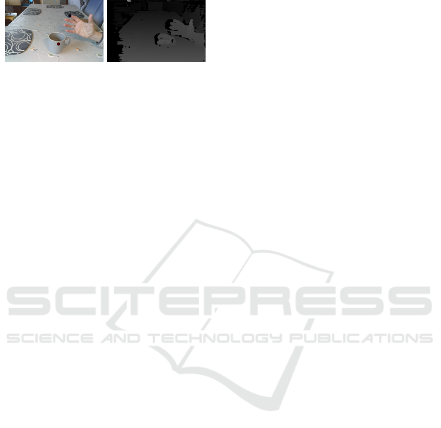
Figure 4: Parallel colour and depth maps images from the
Oak-D camera showing a hand and a mug. The two dots on
the image indicate the location of the index fingertip and the
target location of the mug. The three dimensional location
of each is calculated from the two images combined.
tated for depth estimation. The angle of the camera
causes the vertical (y) coordinate from the colour im-
age to decrease (moving towards the top of the image)
as an object moves along the surface of the table and
away from the camera. To correct for this, a calibra-
tion step is performed. The correction is calculated
empirically by measuring the vertical movement due
to travel away from the camera from while an object
is moved along the flat surface of the table from one
end to the other. The y and z coordinates from the
colour and depth map respectively are recorded and
used to build a simple linear regression model that
maps depth (z) to predicted height ( ˆy), as shown in
equation 1.
ˆy = az + b (1)
The corrected y coordinate, y
∗
is then calculated
by subtracting the predicted ˆy from the measured y.
y
∗
= y − ˆy (2)
While an object is on the table surface, the values
for y
∗
should be close to zero. Our experimental re-
sults found the error to be 4 pixels on average, which
is well within the margin for error that makes the sys-
tem usable.
4 TESTING AND RESULTS
Limited user testing was carried out to measure the
usability of the wristband and the effectiveness of the
computer vision systems. In the user testing experi-
ments, three objects were placed on a table and the
system was used to guide a blindfolded user to a ran-
domly selected item. The items were a cup, a TV re-
mote control and a banana. The camera was mounted
at the end of the table, looking down its length at an
angle that caused the camera image to cover the whole
table top. See figure 4 for an example view. The sys-
tem uses a threshold number of pixels to decide when
the hand has reached its target. Three different val-
ues were tested: 5 pixels, 20 pixels and 40 pixels.
We found that a small threshold meant that the user
often bumped their hand into the object before the al-
gorithm indicated that they had arrived. This is not
a problem as long as there is a way for the user to
end the search process. A larger problem when the
threshold is too small is that the commands can al-
ternate between left and right as the user moves their
hand past the small target zone in one direction and
then in the other direction. A simple rule to detect
this situation is sufficient to avoid it being a problem.
If the required commands alternate in opposite direc-
tions, the algorithm marks the appropriate dimension
as being at the target and either shifts to another di-
mension or announces that the target is found. Larger
thresholds caused the search algorithm to terminate
when the hand arrived at the target, but occasionally
terminated too soon, meaning the user had to blindly
finish the search with small local movements, know-
ing that they were close.
The target location on each image was the centre
of the bounding box given by the object detection al-
gorithm and the target location on the hand was the
tip of the index finger. Future work may address more
sophisticated grabbing guidance, allowing the correct
part of the hand to find the ideal part of the object
(finger and thumb to cup handle, for example) but we
found that once a finger tip has bumped into an object,
the user can easily find the best way to grasp it. The
next sections describe some of the issues that were
discovered during testing and the solutions that were
implemented to overcome them.
4.1 User Preferences and Feedback
Two regimes for sending guidance signals to the hap-
tic motors were tested. The first is to first move the
hand to around 30cm above the table, then to align the
hand with the target in the x plane (left to right), then
to move forwards in the z plane until the hand is over
the object, then to buzz to indicate that moving the
hand down will reach the object. We simplified this
process by requiring the user to start with their hand
on the table right in front of them. A starting sig-
nal (two buzzes to all motors) indicates they should
raise their hand. The guidance then takes over until
two more buzzes indicates that the hand is above the
target. This reduces the full three dimensional navi-
gation space to the two dimensional plane above the
objects one the table. The second regime allows the
hand to stay on the table top and guides it towards the
object on the same plane as the top of the table. This
second regime was more robust as there was no de-
viation in the y axis because the hand stayed on the
table. The advantage of the first regime is that it al-
NCTA 2022 - 14th International Conference on Neural Computation Theory and Applications
320

lows the hand to avoid obstacles that might block a
hand moving at the level of the table top.
4.2 Algorithm Robustness
In the first example, with the donkey images, the ob-
ject detection model was very robust, correctly find-
ing the tail on all of the test images. However, for
the broader object location model the pre-trained sin-
gle shot detector model was not sufficiently robust to
work on all the examples of target objects that were
tried, nor was it able to detect such objects from all
angles. This could often be overcome to some extent
by moving the camera slightly until a detection was
made, but this is not an acceptable solution. In future
work, a more robust model will be trained specifically
on the types of scene the model is expected to see.
4.3 Object Permanence and Occlusion
Images from the camera are processed on a frame by
frame basis and the initial version of the system had
no memory of previous frames. We found that the ob-
ject detection algorithms were not sufficiently reliable
to consistently locate the target object in every frame.
There were also frames in which the object was ob-
scured by the user’s hand. These problems were mit-
igated by storing the last known location of the target
object and guiding the hand towards it until a new lo-
cation is identified.
5 CONCLUSIONS AND FUTURE
WORK
In the introduction we stated that this study would
address two questions: Is the current state of the
art in computer vision sufficiently powerful for this
task, and is a haptic wrist band a practical and usable
modality for user interaction?
Although there were some problems with the ro-
bustness of the object detection algorithm, we may
conclude that recent advances in computer vision
mean that the state of the art is now sufficient to allow
a simple assistive technology for people with sight
loss to work under controlled conditions. It is possible
for a user to perform simple dexterous tasks guided by
computer vision and haptic feedback. Existing object
detection algorithms that are designed to work on flat
images can be extended to work in three dimensions
by pairing a depth map input with a standard colour
input and calculating the distance from the camera to
objects of interest. This means that object detection
algorithms do not have to be re-trained on 3D data.
Correcting the y coordinate of detected objects is sim-
ple when the camera position is fixed, but more work
is needed to accurately locate objects in three dimen-
sions when both the object and the camera position
are mobile.
User experience testing showed that people were
quickly able to learn to follow the haptic feedback and
reach for the target object. The frequency and pattern
of buzz commands is important and user preferences
vary from person to person
Both the hardware and the software for the system
require further development. The wrist band needs
to be miniaturised and enclosed for protection. The
camera system needs to move from a fixed location
to one that is worn on the user’s head or body. This
will also require improvements in the three dimen-
sional image processing as calibration will be more
challenging. The system would also benefit from a
degree of semantic knowledge such as which objects
are dangerous (such as knives), or risk being spilled.
The guidance algorithm should be adjusted to avoid
hazards, partly based on an improved navigation algo-
rithm and partly using semantic knowledge to avoid
risks. We are also adding other modes of guidance
feedback such as speech and localized sound. What’s
more, we are developing a haptic language to allow
the device to send a larger vocabulary of messages
to the user. We are also developing methods to al-
low the user to communicate with the system includ-
ing giving speech commands and hand gesture com-
mands. Videos of the system working can be seen on
the AISLA project website at www.aisla.org.uk.
ACKNOWLEDGEMENTS
Thanks to my project students at the University of
Stirling, Raphael Pattie and Dan Harvey. Thanks also
to the study participants, who tested the wristband and
associated algorithms. This project was approved by
the University of Stirling ethics panel and all partici-
pants gave informed consent.
REFERENCES
Alayon, J. R., Corciega, V. G. D., Genebago, N. M. L., Her-
nandez, A. B. A., Labitoria, C. R. C., and Tolentino,
R. E. (2020). Design of wearable wrist haptic device
for blind navigation using Microsoft Kinect for XBox
360. In 2020 4th International Conference on Trends
in Electronics and Informatics (ICOEI)(48184), pages
1005–1010. IEEE.
A Haptic Interface for Guiding People with Visual Impairment using Three Dimensional Computer Vision
321

Bau, O., Poupyrev, I., Israr, A., and Harrison, C. (2010).
TeslaTouch: Electrovibration for touch surfaces. In
Proceedings of the 23nd Annual ACM Symposium on
User Interface Software and Technology, UIST ’10,
page 283–292, New York, NY, USA. Association for
Computing Machinery.
Bourne, R. R., Adelson, J., Flaxman, S., Briant, P., Bottone,
M., Vos, T., Naidoo, K., Braithwaite, T., Cicinelli, M.,
Jonas, J., et al. (2020). Global prevalence of blind-
ness and distance and near vision impairment in 2020:
progress towards the vision 2020 targets and what the
future holds. Investigative Ophthalmology & Visual
Science, 61(7):2317–2317.
Granquist, C., Sun, S. Y., Montezuma, S. R., Tran, T. M.,
Gage, R., and Legge, G. E. (2021). Evaluation and
comparison of artificial intelligence vision aids: Or-
cam myeye 1 and seeing ai. Journal of Visual Impair-
ment & Blindness, 115(4):277–285.
He, L., Wang, R., and Xu, X. (2020). PneuFetch: Support-
ing blind and visually impaired people to fetch nearby
objects via light haptic cues. In Extended Abstracts of
the 2020 CHI Conference on Human Factors in Com-
puting Systems, pages 1–9.
Howard, A. G., Zhu, M., Chen, B., Kalenichenko, D.,
Wang, W., Weyand, T., Andreetto, M., and Adam,
H. (2017). Mobilenets: Efficient convolutional neu-
ral networks for mobile vision applications. arXiv
preprint arXiv:1704.04861.
Kim, Y., Harders, M., and Gassert, R. (2015). Identification
of vibrotactile patterns encoding obstacle distance in-
formation. IEEE transactions on haptics, 8(3):298–
305.
Lim, J., Yoo, Y., and Choi, S. (2019). Guidance-based two-
dimensional haptic contour rendering for accessible
photography. In 2019 IEEE World Haptics Confer-
ence (WHC), pages 401–406.
Lin, T.-Y., Goyal, P., Girshick, R., He, K., and Doll
´
ar, P.
(2017). Focal loss for dense object detection. In
Proceedings of the IEEE international conference on
computer vision, pages 2980–2988.
Lin, T.-Y., Maire, M., Belongie, S., Hays, J., Perona, P., Ra-
manan, D., Doll
´
ar, P., and Zitnick, C. L. (2014). Mi-
crosoft COCO: Common objects in context. In Euro-
pean conference on computer vision, pages 740–755.
Springer.
Lugaresi, C., Tang, J., Nash, H., McClanahan, C., Uboweja,
E., Hays, M., Zhang, F., Chang, C.-L., Yong, M. G.,
Lee, J., et al. (2019). Mediapipe: A framework
for building perception pipelines. arXiv preprint
arXiv:1906.08172.
Nyman, S. R., Dibb, B., Victor, C. R., and Gosney, M. A.
(2012). Emotional well-being and adjustment to vi-
sion loss in later life: a meta-synthesis of qualitative
studies. Disability and rehabilitation, 34(12):971–
981.
Palani, H. P., Tennison, J. L., Giudice, G. B., and Giudice,
N. A. (2018). Touchscreen-based haptic information
access for assisting blind and visually-impaired users:
Perceptual parameters and design guidelines. In Inter-
national Conference on Applied Human Factors and
Ergonomics, pages 837–847. Springer.
R
¨
oijezon, U., Prellwitz, M., Ahlmark, D. I., van Deventer,
J., Nikolakopoulos, G., and Hyypp
¨
a, K. (2019). A
haptic navigation aid for individuals with visual im-
pairments: Indoor and outdoor feasibility evaluations
of the lasernavigator. Journal of Visual Impairment &
Blindness, 113(2):194–201.
Sadic, A., Ayyildiz, M., and Basdogan, C. (2017). Hap-
tic perception of 2d equilateral geometric shapes via
electrovibration on touch screen. In 2017 21st Na-
tional Biomedical Engineering Meeting (BIYOMUT),
pages i–iv.
Soviak, A. (2015). Haptic gloves prototype for audio-tactile
web browsing. In Proceedings of the 17th Interna-
tional ACM SIGACCESS Conference on Computers &
Accessibility, ASSETS ’15, page 363–364, New York,
NY, USA. Association for Computing Machinery.
NCTA 2022 - 14th International Conference on Neural Computation Theory and Applications
322
