
Human-Robot Collaboration (HRC) with Vision Inspection for PCB
Assembly
Mauro Queirós
1,2 a
, João Lobato Pereira
1,2 b
, Nuno M. C. da Costa
2c
, S. Marcelino
6
,
José Meireles
3d
, Jaime C. Fonseca
2e
, António H. J. Moreira
4,5 f
and João Borges
2,5 g
1
University of Minho, Guimarães, Portugal
2
Algoritmi Center, University of Minho Guimarães, Portugal
3
MEtRICs Research Center, University of Minho, Guimarães, Portugal
4
2Ai – School of Technology, IPCA, Barcelos, Portugal
5
Polytechnic Institute of Cávado and Ave, Barcelos, Portugal
6
DIB4T, Marinha Grande, Portugal
Keywords: Cobot, PCB Assembly, Work Cell.
Abstract: Flexibility and speed in the development of new industrial machines are essential factors for the success of
capital goods industries. When assembling a printed circuit board (PCB), since all the components are surface-
mounted devices (SMD), the whole process is automatic. However, in many PCBs, it is necessary to place
components that are not SMDs, called pin through-hole components (PTH), having to be inserted manually,
which leads to delays in the production line. This work proposes and validates a prototype work cell based on
a collaborative robot and vision systems whose objective is to insert these components in a completely
autonomous or semi-autonomous way. Different tests were made to validate this work cell, showing the
correct implementation and the possibility of replacing the human worker on this PCB assembly task.
1 INTRODUCTION
In today’s industry, any manual operation in
repetitive production lines that causes delays in the
production process needs to be semi-automated or
fully automated so that the factory remains
competitive in an increasingly aggressive and fast
market. Printed circuit boards (PCBs) are a fine
example of such necessity, as they are in virtually all
electronic components of everyday life. Over the
years, assembling electronic components on PCBs
has undergone several changes, many of which aim to
make this process increasingly automated, efficient,
fast, and economically efficient (Altinkemer, Kazaz,
Köksalan, & Moskowitz, 2000; Andrzejewski,
Cooper, Griffiths, & Giannetti, 2018; Bogner,
Pferschy, Unterberger, & Zeiner, 2018; Crama,
a
https://orcid.org/0000-0001-5896-7423
b
https://orcid.org/0000-0002-1053-7405
c
https://orcid.org/0000-0002-8425-3501
d
https://orcid.org/0000-0003-0881-2348
e
https://orcid.org/0000-0001-6703-3278
f
https://orcid.org/0000-0002-2148-9146
g
https://orcid.org/0000-0002-5880-033X
Flippo, Van De Klundert, & Spieksma, 1997). This is
how Surface Mount Technology (SMT) arose, with
surface mount devices (Surface Mount Devices)
being mounted directly on the surface of the printed
circuit board, generally in an automatic way using an
SMT machine. Typically, these components are
smaller in size, have better electrical performance,
must withstand higher soldering temperatures, and
must be selected, positioned, and soldered more
carefully to achieve an acceptable manufacturing
yield (Iftikhar et al., 2020).
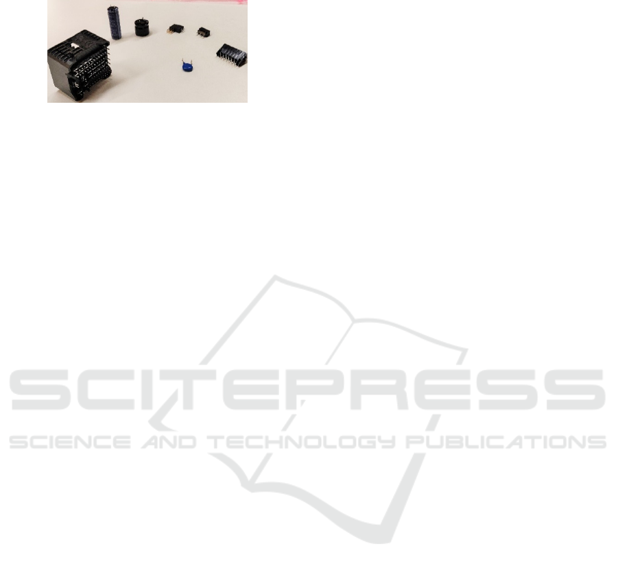
Despite the advances seen with SMDs, there are
other components (Figure 1) that still need to be
manually assembled on PCBs, such as diodes,
capacitors, and connectors named Pin Through Hole
(PTH) components (Wendy Jane Preston, 2018). This
limitation considerably decreases the production
efficiency of PCBs assembled with this type of
56
Queirós, M., Pereira, J., C. da Costa, N., Marcelino, S., Meireles, J., Fonseca, J., Moreira, A. and Borges, J.
Human-Robot Collaboration (HRC) with Vision Inspection for PCB Assembly.
DOI: 10.5220/0011526200003329
In Proceedings of the 3rd International Conference on Innovative Intelligent Industrial Production and Logistics (IN4PL 2022), pages 56-65
ISBN: 978-989-758-612-5; ISSN: 2184-9285
Copyright
c
2022 by SCITEPRESS – Science and Technology Publications, Lda. All rights reserved
components when compared to those that only have
SMD components.
Figure 1: Example of non-SMD components.
Aiming to mitigate the limitation mentioned above
and take advantage of the rise of collaborative robots
(cobots) (Poór, Broum, & Basl, 2019; Vojić, 2020),
this work proposes a novel industrial work cell for the
automatic insertion of non-SMD components into
PCBs. The proposed cell integrates three main
systems from the literature: (1) a cobot to enable either
collaborative or autonomous work (Robotics, 2018);
(2) a vision system for component validation (David
A. Forsyth, 2002; Kurka & Salazar, 2019); and (3) an
external device for controlling and monitoring the
work cell (Langmann & Rojas-Peña, 2016).
Througout this paper, are going to be presented
the fundamental requirements of this work cell, the
layout and the main workflow of this task. It is also
explained the key aspects of each subsystem
methodology, and to validate this work cell, three
tests were made and demonstrated. Finally the results
and main ideas drawn throughout this work are
discussed and concluded.
2 REQUIREMENTS OF THE
WORK CELL
Taking into consideration the goal of reducing or
eliminating the need for manually inserting different
electronic components into PCBs but maintaining
quality and efficiency during the insertion process, a
set of requirements were defined, of which the most
relevant are the following:
• The cell must have an automatic transport
system for the PCB boards;
• It must have the ability to identify the different
PCBs;
• Adapt the program and the gripper according
to the PCB and components to be assembled;
• It must perform accurate and secure gripping
and insertion for the different components;
• The system needs to validate each component
prior to insertion, using, for example, vision
software to read the number of pins and make
sure it is in good condition;
• Needs to assure that the PCB is correctly and
fully assembled within 30 seconds;
• It also requires collecting information relevant
to the operation of the work cell and making it
available in a database for future analysis and
study.
2.1 Cobot Subsystem
Going into more detail about the robot subsystem and
taking into consideration aspects such as the
components under study and the PCBs in question,
the requirements of the robot are: speed and
flexibility, as well as the ability to operate in
conjunction with a human being; at least 700 mm
range; ate least 6 degrees of freedom (DOF); accuracy
and repeatability of less than 0.1 mm; multiple I/O
interfaces; and support for various communication
protocols.
2.2 Vision System
To validate the quality of each component, one of the
most frequently used approaches in the industry is the
use of a vision system. In this case, for the proper
functioning of the work cell, a minimum sensor
resolution of 2M pixels is required to cover the entire
insertion area of the component (500x500 mm2) and
still allow accurate hole inspection and pin integrity
verification. In addition, this system must permit the
sharing of data with other subsystems.
The system must also be able to read the barcodes
in the PCBs and inspect their correct position to
reference the robot with respect to it doing the correct
insertion of all components. For these tasks, the
camera used may have a lower resolution.
2.3 Programmable Logic Control
(PLC) System
Monitoring and recording the activity of an
automated process is paramount, and thus this
subsystem will be responsible for managing the entire
work cell (command, control, and monitoring). For
this to be possible, the external device must comply
with the following requirements: ethernet, RS232,
and EtherCAT communication facilities; digital
inputs and outputs; database iteration facilities, have
OPC-UA; and be modular. As main characteristics,
the same PLC must have database interaction
capabilities and the capacity to make process-relevant
variables available through the OPC-UA protocol.
Human-Robot Collaboration (HRC) with Vision Inspection for PCB Assembly
57
3 LAYOUT AND WORKFLOW
To meet the requirements mentioned above, one can
propose the use of: (1) the cobot TM5-700, a 6 DOF
collaborative robot capable of using different grippers
and that integrates its own vision system; (2) the
FH1050 vision system by Omron, which has various
image acquisition and processing functionalities; and
(3) the NX102-9020 Omron, a PLC acting as an
external device capable of monitoring and controlling
all tasks and functionalities of the work cell. These
proposed systems were used and are connected, using
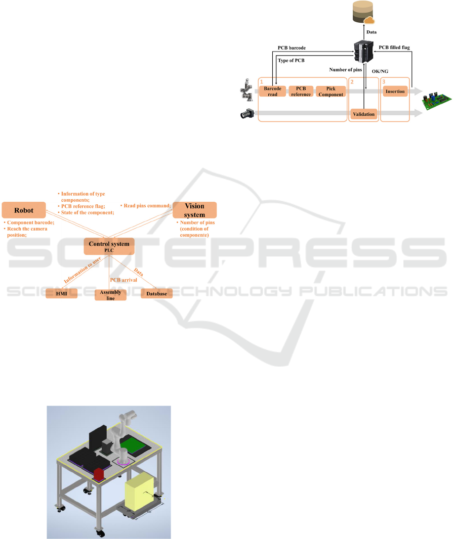
the TCP/IP protocol for data exchange. Figure 2
illustrates how the subsystems interact throughout the
task. In short, the PLC receives a signal from the
assembly line to start the flow, and, after that,
different signals are exchanged between the cobot,
the PLC, and the vision system to proceed with the
task. All the essential information to be seen by the
human worker is visible in an interface and then sent
to a database.
Figure 2: Data exchanged between the three subsystems.
The work cell further includes one box for the
damaged components, the PCB allocation zone, and
other zones for the boxes of the different types of
components. Figure 3 shows a sketch of the work cell,
illustrating all the components mentioned above
distribution.
Figure 3: Sketch of the work cell.
With this distribution, the cobot can reach every
position needed, independently of the velocity chosen
for the task, without too much torque effort.
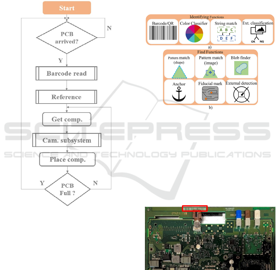
In a simplified way, the general task flow of this
work cell is shown in Figure 4.
Figure 4: Flow of the work cell.
In short, the cobot will start by reading the
barcode on the PCB to know what components must
be inserted and do the referencing task to know where
the PCB is. After that, it is time for the external vision
system to read the number of pins each component
has to validate its quality. Depending on the
information received, the cobot will discard the
component or place it in the proper PCB position
upon the validation task. After placing the
component, if the PCB is not yet fully assembled, the
cobot will repeat the operation for another
component. When finished, it will wait for the arrival
of a new PCB.
4 METHODOLOGY
To execute the workflow explained above, one should
consider each subsystem individually and how to
integrate them to focus on precision and speed,
aiming to respect the following key goal: replace the
worker in the assembly of PCBs with this type of
components, trying to speed up the process and
reduce costs without ever losing quality.
To understand the entire process of this work cell,
each subsystem will be explained in a more detailed
way.
4.1 Cobot Subsystem
The cobot will have two major tasks: first, it is the
subsystem responsible for the movement in the main
task, including picking up a component, taking it to
the vision subsystem, and, finally, placing it in the
right location on the PCB. The other part is regarding
IN4PL 2022 - 3rd International Conference on Innovative Intelligent Industrial Production and Logistics
58
the internal vision system that this cobot has. Here,
the cobot will perform two analyses: read the PCB's
barcode to know which component to insert and
reference itself with respect to the assembly board
before inserting the first component (Figure 5). Both
tasks will be solved using the TMFlow software,
whereas, for the vision tasks, the TMvision software
is employed.
Figure 5: Workflow of the cobot subsystem.
4.1.1 Motion
Regarding this part of the task, the robot will have to
move around the work cell to reach the desired
positions, with the highest possible precision and
speed, without compromising the safety of the
environment and operator.
First, it will start in its home position, and as soon
as the PCB sensor is activated, the robot moves to the
zone where it will do the barcode reading and the
referencing task. Upon gathering the information
needed, the cobot picks the specific PCB component
and moves it to the zone where the external camera
will check the integrity of the pins. After validating
the integrity of the component, the robot proceeds to
the insertion of the same.
4.1.2 Cobot Vision System
To identify the PCB that just arrived and place the
components in the correct position, even if the PCB
comes tilted or just crooked, the cobot's internal
vision system has two types of functionalities (Figure
6) (Omron, 2020).
Figure 6: Functionalities available in the cobot’s internal
vision system: a) identify functions; b) find functions.
Every PCB comes with an associated barcode to
know precisely which type (and amount) of
component that PCB takes. To this end, the
Barcode/QR code identify function is employed.
Here, it is necessary to specify the region where the
barcode can appear, and once the camera reads a
barcode, it returns the specific number of that PCB.
Knowing the group to which that particular number
belongs, it is possible to tell which components must
be inserted (Figure 7).
Figure 7: Example of a barcode in a PCB.
For PCB referencing, the Fiducial mark find
function is employed. Fiducial marks are small
targets in an assembly board placed on the top copper
layer (and bottom if it is 2-layers) and allow the vision
system to recognize where the PCB is (Figure 8).
Human-Robot Collaboration (HRC) with Vision Inspection for PCB Assembly
59
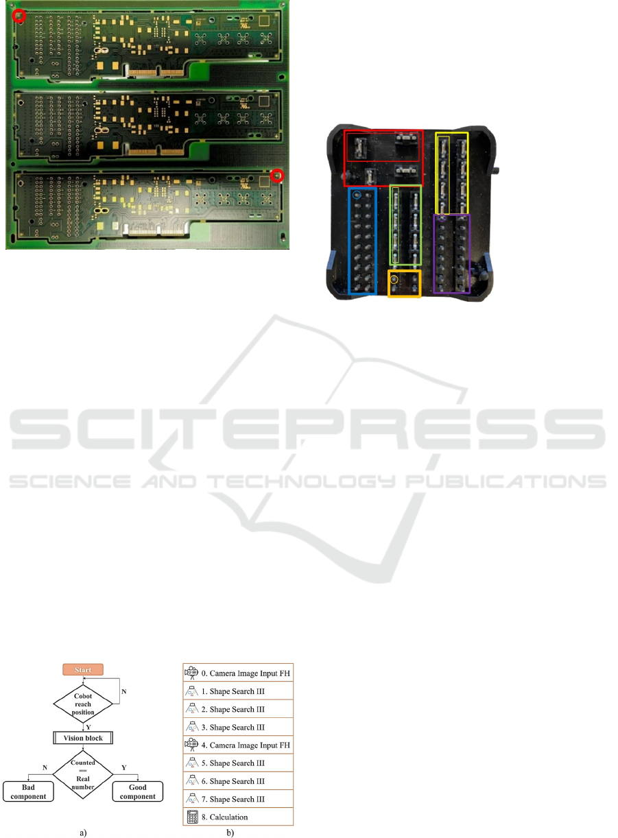
Figure 8: Examples of fiducial marks in a PCB.
The fiducial marks, the target study area, and the
similarity threshold need to be selected to use this
function properly. Once the cobot reaches the
position to do the referencing, it will find the fiducial
marks and create a new coordinate frame, where the
middle point between the two fiducial marks is the
origin. From this point on, regardless of the position
of the PCB, the cobot will always be able to make the
same movement to the insertion positions, ensuring
the correct filling of the board.
4.2 FH Vision Subsystem
Here, the objective is to ensure that the component
that the cobot will insert is in good condition to be
possible to insert into the PCB without wasting it.
Usually, this is solved by human inspection, but the
goal is to replace it with a vision system to make the
work cell fully automatic and faster.
The FH-1050 vision system is used, taking
advantage of the FZ-PanDA software (Omron).
Figure 9 summarizes the tasks peformed by the vision
system.
Figure 9: a) Workflow; b) vision block.
In brief, upon waiting for the cobot with the
component to reach the point where the camera is
pointing, the system will make one single acquisition
to count the number of pins in a certain area to check
if they are damaged. The idea is to divide the
component into small sections, each with a specific
number of pins or groups/lines of pins (Figure 10).
Figure 10: Component divided into sections and number of
pins of each section.
This procedure is done using the "Shape Search
III" block, where we must select the region of interest
(ROI; big red box) and the subject we want to look
for in that exact area (small red box, for example).
Through an object detection algorithm, this function
block registers a model of an image pattern based on
its contour information, detects parts of inputted
images that most closely match the model, and adds
each similar object to the total count. An experimental
study was performed to select the suitable threshold
value for the degree of similarity between the
template and the new image. Afterwards, the
"Calculation" block is employed to find the total
number of pins that were identified in each "Shape
Search III" block. If the number equals those
expected for the component in question (44 in the
example in figure 10), the component is in good
condition, and therefore the cobot will proceed with
its insertion. If not, the cobot will discard this
component, placing it in a specific box for damaged
components.
Of note, the other two blocks present in figure 10,
the "Camera Image Input FH", are used to calibrate
the camera and enhance the image between analyses
.
4.3 PLC Subsystem
This subsystem aims to establish a connection
between the other two subsystems, being responsible
for the control and monitoring of the work cell and
registering the relevant data during the execution of
the task, to be later stored in a database. The kind of
Red – 2 groups
Yellow – 2 lines
Green – 2 lines
Blue – 20 pins
Purple – 14 pins
Orange – 4 pins
TOTAL: 44
IN4PL 2022 - 3rd International Conference on Innovative Intelligent Industrial Production and Logistics
60
data to keep track of includes, for example, the
number of damaged components, the number of
PCBs filled, the time it takes to fill each board type,
and so on. Figure 4 summarizes the information
exchanged between subsystems, and as shown, the
whole process of this task is divided into three main
parts.
First, the cobot waits for the PLC to tell it that a
new PCB has arrived. Then, as mentioned before, the
cobot will use its internal vision system to do the
referencing task and to read the barcode, sending the
reading signal to the control system. Here, the PLC
will then decide what type of PCB it is and then tells
the cobot what type of components to insert.
Upon picking up the component, the cobot will
take it to the external vision system area. Here, the
PLC will send two commands: (1) first the command
measurement, where the system will run the code to
count the number of pins to assess the component’s
condition; and (2) the get data command, where the
PLC will receive from the external vision system the
number of pins that the software detected. Then, the
PLC compares this value with the expected value, and
if the result is positive, it informs the cobot that it can
proceed with the insertion. If it is not, the PLC
informs the cobot to discard this component and pick
a new one.
Finally, the cobot will proceed with the insertion
of the good component, repeating these steps until the
PCB is filled. Meanwhile, the PLC will store relevant
data during these steps, such as the number of PCBs
filled, the number of damaged components, and the
time to fill one PCB, among others.
Table 1 explains how the information will flow
between the three subsystems.
Table 1: Information exchange.
PLC takes PLC sends
PCB sensor - PCB
arrived at the assembly
area
Signal/Message for
cobot to start
PCB barcode from
the cobot reading.
Type of PCB for
cobot to know which
type of components it
takes
External vision
system reached
Measure command
for vision system
------------------ Get data command
for vision system
------------------ OK/NG component
for cobot
PCB assemble
d
------------------
5 TESTS
This section demonstrates some practical examples of
this work cell, showing the correct implementation of
the main systems and the compliance with the
requirements. The tests were:
• Test A: How much time does it takes for the
cobot to fill a PCB;
• Test B: Reliability of the external vision system;
• Test C: Monitoring and data acquisition.
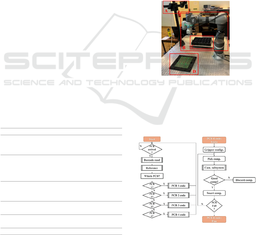
These tests were employed in the following
environment, where it is possible to see: (A) the
external vision system for inspection; (B) the cobot
with the internal vision system for barcode reading
and referencing; (C) the box of components; (D) the
PCB (Figure 11).
Figure 11: Environment of the work cell.
5.1 How Much Time Does It Take for
the Cobot to Fill a PCB
In this test, the idea was to run the full task of this
work cell and see how long it takes to fill a PCB,
repeating this trial for different velocities (Figure 12).
Figure 12: Workflow of the main task for PCB type 4.
Human-Robot Collaboration (HRC) with Vision Inspection for PCB Assembly
61
The max velocity was set to 1.5 m/s, and the trials
were done for 20%, 40%, 60%, 80%, and 100% of
that speed. Of note, it was possible to see that the
cobot never reaches the max speed because the
movements that it makes during this task do not have
the range needed to reach that velocity. Table 2 shows
the time recorded for each speed setting.
Table 2: Time to fill a PCB with different speeds.
Velocity Time (m/s)
20% 0:59,260
40% 0:38,672
60% 0:31,313
80% 0:29,241
100% 0:28,039
It is possible to conclude that the cobot needs less
than 30 seconds to fill a PCB of type 4 (one that takes
three components).
So far, one has shown that the robot can indeed
meet the mentioned requirements, both in terms of
speed and efficiency, but we have not observed its
added value over the human operator. Thus, some
additional tests were performed, where an operator
tried to insert the components manually without
validation of any kind. Despite initially taking around
20 seconds to fill a PCB, this time was reduced to an
average of 15 seconds after a few attempts. The same
type of test was executed using the cobot, observing
a time of 16.280 seconds. Overall, it is possible to
conclude that the cobot, besides being able to
maintain this pace continuously, does not present
significant delays over an operator, as it takes only 12
seconds more to fill the PCB while also inspecting it
as well as the components.
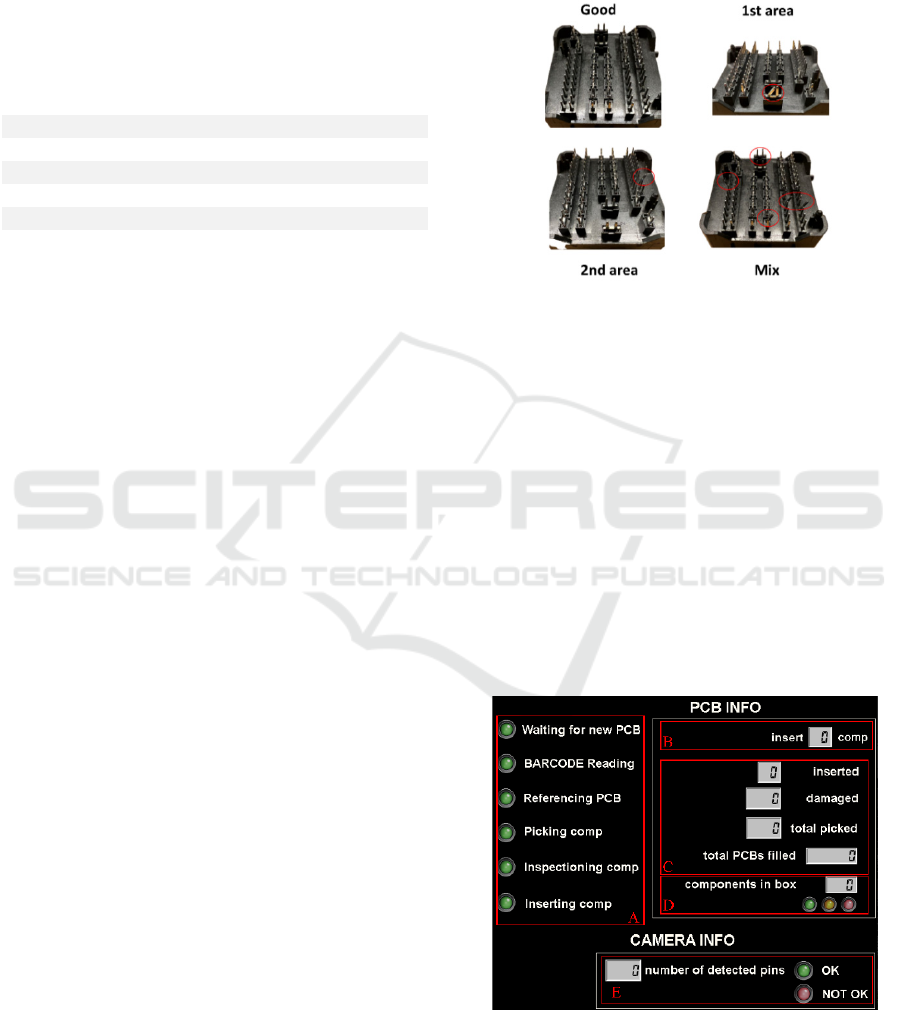
5.2 Reliability of the External Vision
System
This last test aims to confirm if the external vision
system has the capacity and reliability to validate
different types of damaged components. For that,
different components were structurally compromised
in different areas, and the task was run ten times to
inspect how many true positives the vision system
could detect. Additionally, the same test was run for
one good component to validate if the system could
validate its integrity either (Figure 13).
During the ten trials of each test, the external
vision system showed its reliability when validating
the components, verifying that it is in bad condition
in all of the examples mentioned above, except for the
case of a "good” component. Moreover, it also has the
capability of showing in which area the damage is,
presenting a result of 10 out of 10 successful
validations. From the moment the cobot reaches the
inspection zone, and the moment the main system
(PLC) receives the answer, the camera only needs
around 0,8-1s to process all this.
Figure 13: Examples of the components used.
5.3 Monitoring and Data Acquisition
The goal here is to test whether the PLC can retrieve
the necessary information during the execution of the
task mentioned above to be later able to visualize and
document this data. The number of components and
the number of PCBs filled with each type are
examples of data that needed to be retrieved to be
easier for the co-worker to know, for example, when
to change the empty box of components, to know the
percentage of damaged components or the number of
PCBs of type 3 filled in one day.
To check the retrieved information, an interface
was built using the CX-Designer software (Figure
14).
Figure 14: CX-Designer interface.
Figure 14 illustrates the five main parts of the
interface:
IN4PL 2022 - 3rd International Conference on Innovative Intelligent Industrial Production and Logistics
62

• Section A notifies about the steps being
performed during the routine;
• Section B informs the type of PCB detected
during the barcode read function and the number
of components it takes;
• Section C presents the number of components
inserted, the number of damaged components,
and the total number of picked components;
• Section D informs the number of components
left in the box, showing a yellow LED when it
is almost empty, and a red LED when it is
empty;
• Section E lets know the number of pins read,
showing the result of the external vision system.
Figure 15 shows a possible sequencing of what
can be observed in the interface over several
iterations.
Two images were recorded during the filling of
the first PCB (Figure 15-1 and Figure 15-2). The first
one shows the pick and place task and the validation
task of the first component, where it is possible to see
the number of pins read by the external vision system
validating the component and resulting in its
insertion. The second shows the expected last
component of that PCB, where it was a damaged
component, showing 42 read pins instead of 44, and
a total of one damaged component out of a total of
three. The last figure (Figure 15-3) illustrates an
example of a possible iteration of the interface during
a day of work.
6 DISCUSSION
During Test A, we confirmed the accomplishment of
the 30 second requirement. We performed some
insertion trials to compare this with a human worker,
concluding that the worker can be faster by 1.280
seconds on average. However, some major
requirements need to be considered, like efficiency,
repeatability, and precision. Humans are susceptible
to tiredness, and after hours of work, their precision
and efficiency will not be the same, leading to delays
in production or, in worst cases, damaged PCBs. In
opposition, the cobot always performs at his highest
level, sustaining these requirements throughout hours
of work. These requirements are also possible with
industrial robots, but they have some disadvantages,
such as: they are usually more expensive, they are
used for heavier payloads, and they also require an
isolated work area.
Moreover, different camera positions were tested
during this test to find the easiest and fastest way to
achieve a more efficient work. When the camera is on
top, the environment lightning variations do not affect
the external vision system precision and fast decision
making. There were still two other possibilities: one
being the cobot’s camera performing the inspection,
however this camera did not present the minimum
requirements for this process; and the other was an
external camera attached to the cobot, which met the
quality and resolution requirements, but increased the
cycle time of the entire process since the robot would
need to place the component in an intermediate
position to take the reading.
Test B confirms the high level of inspection by the
external vision system when validating minor
displacements and defects of the components’ pins. It
thus delivers a sensibility and accuracy that a human
eye cannot achieve.
One of the few tasks in this work cell that a human
worker needs is replacing an empty component box.
In Test C, one concluded that this type of information
cannot be presented as a mere label but also needs to
be displayed using three LEDs, representing the
quantity of components left in the box, giving an
explicit luminous warning to the human worker. In
addition to this task, to reduce the cycle time of this
process, the operator cooperates with the cobot by
informing it of the limited barcode search area since
each type of PCB has its barcode in different areas.
Test C confirms the high level of inspection by the
external vision system when validating minor
displacements and defects of the components’ pins. It
thus delivers a sensibility and accuracy that a human
eye cannot achieve.
As mentioned before, the human worker could
replace some functionalities of this work cell, like the
Human-Robot Collaboration (HRC) with Vision Inspection for PCB Assembly
63
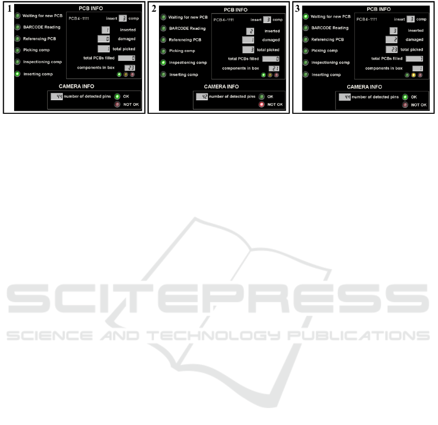
Figure 15: Interface during sequenced iterations.
barcode read and the referencing functions. Here,
the worker could be responsible for informing the
cobot of what type of components should be inserted.
However, the idea is to minimize the human
interaction, and through the barcode read function is
possible to pass this information in an autonomous
way without wasting much time. Also, when using
the referencing function, we guarantee the correct
placement of each component, as even when using a
mechanical interlock, there is no guarantee of the
correct PCB orientation, which over time can cause
displacements in the order of millimeters.
In addition to the solution proposed throughout
the paper, other two approaches were considered. The
first one considered the collaboration between human
and robot in a way that the robot would perform the
pick task and take it to the vision system, and after the
component validation, it would be inserted by the
human, having the transference of it between the
cobot and the operator. On the other hand, in the
second hypothesis, the operator would perform the
validation task of the component, and after it was
validated, it would be transferred between the
operator and the cobot, and the cobot would perform
the insertion part. Both solutions have disadvantages
since they increase the cycle time of the process, with
the transition of the component between the operator
and the cobot, as well as relying on less accurate and
precise systems.
7 CONCLUSION
In this work, was presented a solution to a prototype
autonomous work cell capable of assembling PCBs
with PTH components. This work cell consisted of
three main systems: (1) the cobot; (2) the vision
system; and (3) the PLC, exchanging information
between them via TCP/IP protocol.
The first one is mainly responsible for the
movement in the main task, including picking up the
components, taking them to the inspection area, and
inserting them into the PCB. The vision subsystem
ensures the precise positioning and identification of
the PCB and verifies the components’ condition. The
last subsystem manages both the cobot and external
vision system’s interactions and is responsible for
monitoring the work cell by registering the relevant
data generated during the execution of the task and
storing it in a database.
Hereto, the three subsystems were demonstrated
and explained, always showing the key aspects of the
creation of this work cell. The performance of the
proposed work cell was demonstrated through three
examples, focusing on the most important aspects,
namely exchange and acquisition of information, the
validation of components, and the gain in precision
and speed during PCB assembly over a human
operator, all of them showing positive and successful
results.
In sum, this work proves the optimization of a
human process. It proves the possible replacement of
the main human tasks with systems that are capable
of maintaining a high level of performance
throughout long periods of time.
ACKNOWLEDGEMENTS
This work is co-funded by the European Regional
Development Fund (ERDF) through the Operational
Competitiveness and Internationalization Programme
(COMPETE 2020) of the Portugal 2020 Program
[Project No. 45070, "FlexASComp”; Funding
Reference: POCI-01-0247-FEDER-045070].
REFERENCES
Altinkemer, K., Kazaz, B., Köksalan, M., & Moskowitz, H.
(2000). Optimization of printed circuit board
IN4PL 2022 - 3rd International Conference on Innovative Intelligent Industrial Production and Logistics
64

manufacturing: Integrated modeling and algorithms.
European journal of operational research, 124(2), 409-
421.
Andrzejewski, K., Cooper, M., Griffiths, C., & Giannetti,
C. (2018). Optimisation process for robotic assembly of
electronic components. The International Journal of
Advanced Manufacturing Technology, 99(9), 2523-
2535.
Bogner, K., Pferschy, U., Unterberger, R., & Zeiner, H.
(2018). Optimised scheduling in human–robot
collaboration–a use case in the assembly of printed
circuit boards. International Journal of Production
Research, 56(16), 5522-5540.
Crama, Y., Flippo, O. E., Van De Klundert, J., & Spieksma,
F. C. (1997). The assembly of printed circuit boards: A
case with multiple machines and multiple board types.
European journal of operational research, 98(3), 457-
472.
David A. Forsyth, J. P. (2002). Computer Vision - A
Modern Aproach.
Iftikhar, B., Malik, M., Hadi, S., Wajid, O., Farooq, M.,
Rehman, M., & Hassan, A. (2020). Cost-effective,
Reliable, and Precise Surface Mount Device (SMD) on
PCBs. Paper presented at the IOP Conference Series:
Materials Science and Engineering.
Kurka, P. R. G., & Salazar, A. A. D. (2019). Applications
of image processing in robotics and instrumentation.
Mechanical Systems and Signal Processing, 124, 142-
169.
Langmann, R., & Rojas-Peña, L. F. (2016). A PLC as an
Industry 4.0 component. Paper presented at the 2016
13th International Conference on Remote Engineering
and Virtual Instrumentation (REV).
Omron. FH/FHV/FZ5 Series Vision System - Processing
Item Function Reference Manual. Retrieved from
https://www.edata.omron.com.au/eData/manuals.html
Omron. (2020). Software Manual TMvision. Retrieved
from
https://www.edata.omron.com.au/eData/manuals.html
Poór, P., Broum, T., & Basl, J. (2019). Role of collaborative
robots in industry 4.0 with target on education in
industrial engineering. Paper presented at the 2019 4th
International Conference on Control, Robotics and
Cybernetics (CRC).
Robotics, I. F. o. (2018). Demystifying Collaborative
Industrial Robots. Frankfurt, Germany.
Vojić, S. (2020). Applications of collaborative industrial
robots. Machines. Technologies. Materials., 14(3), 96-
99.
Wendy Jane Preston. (2018). The difference between THT
and SMT. Retrieved from https://www.harwin.com/
blog/the-difference-between-tht-and-smt/
Human-Robot Collaboration (HRC) with Vision Inspection for PCB Assembly
65
