
Analysis of Six-pulse Rectifiers’ Switching to Half-phase Mode
Boris Arzhannikov, Andrey Shtin, Irina Paderina, Timofey Tarasovskiy and Leonid Frolov
Ural State University of Railway Transport, Yekaterinburg, Russia
Keywords: Traction power supply, three-phase electric traction system, six-pulse rectifiers, open phase mode, basic
ratios.
Abstract: In contrast to the DC and single-phase AC electric traction systems existing on the electrified railways of
the world, in the developed three-phase electric traction system, when one phase of power supply (one of
two wires of contact network) is switched off, it becomes necessary to switch three-phase equipment of
electric rolling stock, in particular six-pulse bridge rectifiers, into the partially phased mode. In this
connection, the features of six-pulse bridge rectifiers operation are considered in this article. The
instantaneous schemes of six-pulse bridge rectifiers operation in the partial phase mode and also vector
diagrams of transformer secondary winding voltages connected by "star-delta" and "star-star" schemes in
the full- and open phase modes of three-phase systems of traction power supply are presented. Based on the
studies carried out, the relations of the connecting voltages, currents and powers of the considered six-pulse
bridge rectifiers in the open phase mode are presented for both controlled and uncontrolled converters.
1 INTRODUCTION
Many countries are now actively developing new
electric traction systems for mainline railways
(Arzhannikov, 2015; Arzhannikov, 2019;
Arzhannikov, 2019a; Belany, 2019; Chen, 2021;
Fletcher, 2020; Frey, 2012; Jefimowski, 2018;
Kaudia, 2017; Ľuptáka, 2020; Song, 2020; Tlili,
2020; Yang, 2019). A detailed analysis of such
systems is performed in the monograph
(Arzhannikov, 2019), according to which the most
promising direction in this area is the three-phase
power supply system (Belany, 2019).
The research conducted in (Arzhannikov, 2019)
showed that when using three-phase electric traction
system on the electrified sections of railways, it is
necessary to switch the three-phase equipment of
electric rolling stock, in particular six-pulse
rectifiers, into an open phase mode. The present
article is devoted to consideration of peculiarities of
operation of these converters in this mode.
Description of processes occurring in six-pulse
rectifiers will be made under the following
assumptions:
1) active and reactive resistances of supplying
network and converter transformer are equal
to zero;
2) resistances of diodes in forward direction are
equal to zero and in reverse direction are equal
to infinity;
3) the load is a counter-EMF Ed and a smoothing
reactor with inductive resistance equal to
infinity Хd = ∞.
The phases of the primary windings are in capital
letters and the phases of the secondary windings are
in lower case letters.
2 MATERIALS AND METHODS
Rectifiers with full-phase operation correspond to
the values without dashes, while the values with
dashes correspond to the values with open phase
operation.
When the load voltage changes, the inverter can
operate according to several algorithms. We will
consider two of them:
− Algorithm 1 - load remains constant
regardless of rectified voltage (Zd = const);
this operating algorithm will correspond to the
values with the index (A1);
− Algorithm 2 - the load is varied so that the
incoming power remains constant (Рd = Ud ∙
Id = const); this operating algorithm will
correspond to the values with the index (A2).
338
Arzhannikov, B., Shtin, A., Paderina, I., Tarasovskiy, T. and Frolov, L.
Analysis of Six-pulse Rectifiersâ
˘
A
´
Z Switching to Half-phase Mode.
DOI: 10.5220/0011584900003527
In Proceedings of the 1st International Scientific and Practical Conference on Transport: Logistics, Construction, Maintenance, Management (TLC2M 2022), pages 338-343
ISBN: 978-989-758-606-4
Copyright
c
2023 by SCITEPRESS – Science and Technology Publications, Lda. Under CC license (CC BY-NC-ND 4.0)
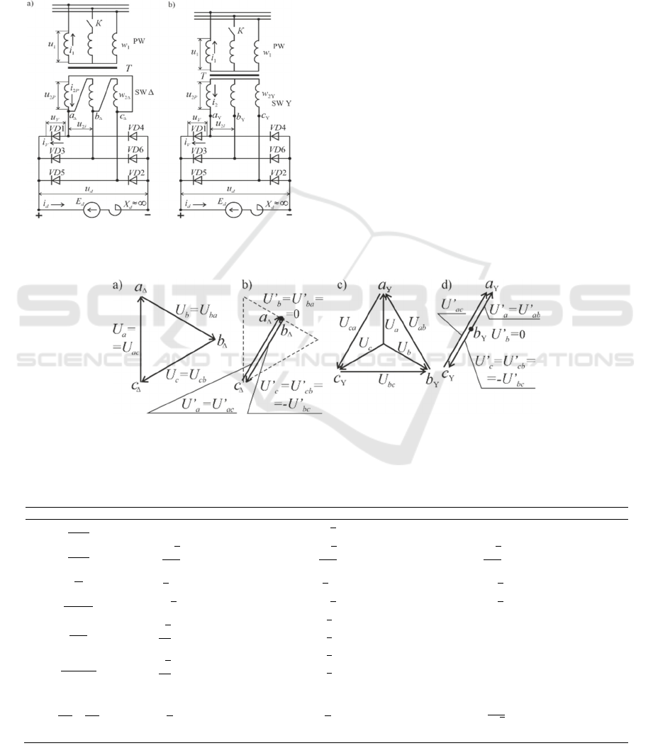
Six-pulse converter circuit diagrams for
star/delta connection of transformer windings
(6Y/Δ) and star/star (6Y/Y) and are shown in
Figures 1, a and b respectively. Each consists of a
converter transformer T, with primary (PW) and
secondary (SW) windings connected in delta
respectively (SW Δ) or star (SW Y), and six diodes
(VD1 — VD6).
Figure 1: Schematics of 6Y/Δ (a) and 6Y/Y (b) rectifiers.
When the K key is closed (Figures 1, a and b),
the circuits operate in all-phase mode. The vector
diagrams of the phase and line voltages of their
secondary windings for this mode are shown in
Figures 2, a and b respectively. The rectified
voltages 6Y/Δ and 6Y/Y are generated by the apex
line voltages of the transformer secondary windings
and have six fluctuations per supply period (Wang,
2018).
In full-phase mode of these converters, the
relations between voltages, currents and powers are
determined by the known expressions (Worku,
2018), which are given in Table 1. In the same table
similar relations for two-pulse bridge rectification
scheme (2B) are given (Worku, 2018).
Table 1 indicates:
U2L, U2PH — effective values of line and phase
voltages of transformer secondary windings;
Ud0, Id — average values of no-load voltage and
rectifier current;
IV — average current of the rectifier's valve arm;
UV MAX — maximum reverse voltage of the
rectifier valve arm;
I2PH, I1PH — effective values of phase currents
Figure 2: Vector diagrams of secondary winding voltages 6Y/Δ (a, b) and 6Y/Y (c, d) full-phase (a, c) and single-phase (b,
d) modes.
Table 1: Relationship between voltages, currents and powers of six-pulse (6Y/Δ, 6Y/Y) and two-pulse bridge (2B)
rectifiers in full-phase mode with different secondary winding arrangements.
Paramete
r
6М Y/Δ 6М Y/Y 2B
𝑈
𝑈
1 (1)
√
3
= 1.732
(8) 1 (15)
𝑈
𝑈
3
√
2
𝜋
1.35
(2)
3
√
6
𝜋
2.339
(9)
2
√
2
𝜋
0.9003
(16)
𝐼
𝐼
1
3
0.3333
(3)
1
3
0.3333
(10)
1
2
0.5
(17)
𝑈
𝑈
√
2
= 1.414
(4)
√
6
= 2.449
(11)
√
2 = 1.414
(18)
𝐼
𝐼
√
2
3
0.4714
(5)
2
3
0.8165
(12) 1 (19)
𝐼
∙𝑘
𝐼
√
2
3
0.4714
(6)
2
3
0.8165
(13)
1
(20)
𝑆
Н
𝑃
𝑆
Н
𝑃
𝜋
3
1.047
(7)
𝜋
3
1.047
(14)
𝜋
2
√
2
1.111
(21)
Analysis of Six-pulse Rectifiersâ
˘
A
´
Z Switching to Half-phase Mode
339

of transformer secondary and primary windings;
𝑘
— transformation ratio;
w1, w2 — number of turns of primary and
secondary windings of the transformer;
S2Н, S1Н — rated power ratings of transformer
secondary and primary windings;
S2Н = 3∙U2Н∙I2Н, S1Н = 3∙U1Н∙I1Н — rated
power ratings of transformer secondary and primary
windings;
Рd0 = Ud0 IdH∙— notional rated power at the
rectifier output.
3 RESULTS AND DISCUSSION
We will consider the operation of 6Y/Δ when the
connection between mains and phase B is open, i.e.,
when the key K in figure 1, a is open.
In this case, the circuit will switch to an
incomplete phase mode. Phase voltages and currents
В and bΔ are equal to zero. Only the phases A, С, aΔ
and сΔ are involved.
The vector diagrams of the phase and line
voltages of the secondary 6Y/Δ open phase
transformer are shown in Figure 2, b. From this
figure it can be seen that the phase voltages aD and
сD (U’a and U’с), and linear (U’aс and U’сb) are
reduced cos π/3 times, and modulo become equal to
each other:
𝑈′
𝑎
𝑈′
𝑎𝑐
𝑈′
𝑐
𝑈′
𝑐𝑏
𝑈′
𝑏𝑐
𝑈
2𝐿
∙
𝑐𝑜𝑠
𝜋
3
√
3
2
𝑈
2𝑃𝐻
. (22)
Thus, the six-pulse rectifier circuit of the inverter
in question is converted into a two-pulse bridge
circuit when the B phase circuit is interrupted. As a
single-phase secondary voltage, two phase voltages
of equal magnitude and direction are connected in
parallel (u’a and -u’с) or linear (u’aс and u’bс)
voltages, of those phases which are not in phase
mode. In the case of a disconnection in phase A,
these will be u’ab and u’cb, and in the phase С these
will be u’aс and u’ab.
Since the break occurs in phase B, there will be
voltages applied to the rectifier u’ac and u’bc, the
amplitudes of which are
√
3
2
less than the
amplitudes of the voltages uac and ubc of the full-
phase mode (Figure 2, b).
At the interval where the highest potential at the
point aΔ and bΔ, and the smallest at the point сΔ
(Figure 3, a), the current flows as follows. The first
half of the load current flows out of the point aΔ,
and the second from the point bΔ. Running through
VD1 and VD3 respectively, these currents are
connected at the common cathode of the rectifier,
and then through the load circuit and VD2. They
then branch out again at the point сΔ, passing
through the phases aΔ and сΔ. Voltage is applied to
the load u’ac(bc) (Figure 2, b), and the rectifier
operates VD1, VD3 and VD2 (Figure 3, a).
At the interval where the highest potential at the
point сΔ, and the lowest – at the point aΔ and bΔ.
(Figure3, b), the load current flows through the
circuit: point cΔ, VD5, load. The current then splits -
the first half flows through the VD4 circuit, point
aΔ, phase aΔ, point сΔ, and the second by the circuit
VD6, point bΔ, phase cΔ, point сΔ. Voltage u’ca(сb)
is applied to the load (Figure 2, b), and VD5, VD4
and VD6 operate in the rectifier (Figure 3, b).
Figure 3: Instantaneous 6Y/Δ operation diagrams in an
open phase mode.
Since 6Y/Δ operates as a two-pulse rectifier in
partial phase mode, its average rectified voltage can
be found from the expression (16). Therefore,
according to (22), (1) and (2), we obtain:
𝑈
′
𝑑0
2
√
2
𝜋
∙𝑈
′
2
2
√
2
𝜋
∙𝑈
2𝑃𝐻
∙
√
3
2
√
6
𝜋
∙𝑈
2𝑃𝐻
1
√
3
∙𝑈
𝑑0
. (23)
It follows from (23) that the rectified voltage
6Y/Δ is reduced by a factor of 1.732 when there is
an open circuit in any phase of the primary winding.
If the inverter operates according to Algorithm 1
(Zd = const), then the rectified current is reduced by
the same amount and the power delivered to the load
is reduced by a factor of 3:
𝐼
√
∙𝐼
, (24)
𝑃
𝑈
∙𝐼
√
∙𝑈
∙
√
∙𝐼
∙𝑃
. (25)
If the inverter operates according to Algorithm 2
(Pd = const), then the rectified current 6Y/Δ in
partial phase mode must increase as much as the
voltage has decreased, i.e., 1.732 times
TLC2M 2022 - INTERNATIONAL SCIENTIFIC AND PRACTICAL CONFERENCE TLC2M TRANSPORT: LOGISTICS,
CONSTRUCTION, MAINTENANCE, MANAGEMENT
340

𝐼
′
𝑑𝐴2
√
3 ∙𝐼
𝑑
. (26)
Figure 3 shows that the currents of the diodes
differ from each other when 6Y/Δ is operating in an
open phase mode. In the example we are
considering, the currents of VD2 and VD5 are twice
the currents of VD1, VD3, VD4, VD6. Therefore,
according to (17), we can write that the average
current value of VD2 during 6Y/Δ operation in an
open phase mode will be equal for Algorithm 1,
considering (24) and (3), and for Algorithm 2,
considering (26) and (10),
𝐼′
√
∙𝐼
√
∙𝐼
; 𝐼′
√
∙𝐼
√
∙𝐼
. (27)
In a two-pulse bridge rectifier circuit, the
transformer secondary voltage (18) is applied to the
diodes which are not in operation. Therefore, taking
into account (18) and (4), we will write that the
maximum reverse voltage of the valve arm 6Y/Δ in
an open phase mode is:
𝑈′
√
2 ∙𝑈
√
2 ∙𝑈
∙𝑈
√
∙𝑈
. (28)
Figure 3 shows that when 6Y/Δ is operating in
open phase mode, the phase currents aΔ and сΔ are
the same and equal to half the id load current. On
this basis, taking into account (19), it can be written
that the effective value of the phase current aΔ 6Y/Δ
in an open phase mode is equal to
𝐼′
∙𝐼′
. (29)
For Algorithm 1, considering (29), (24) and (5),
and for Algorithm 2, considering (29), (26) and (5),
we obtain:
𝐼′
√
∙𝐼
√
√
∙𝐼
; 𝐼′
√
∙
𝐼
√
√
∙𝐼
. (30)
Following a similar reasoning according to the
expressions (20), (24), (26), (6) for the A phase
current of the transformer's primary, we write:
𝐼′
√
√
∙𝐼
; 𝐼′
√
√
∙𝐼
. (31)
Using the expressions (23)-(26), (30), (31), we
find the calculated secondary and primary power
ratings for 6Y/Δ open phase operation
𝑆
Н
𝑆
Н
3∙𝑈
Н
∙𝐼
Н
√
∙
𝑃
√
√
∙𝑆
Н
; (32)
𝑆
Н
𝑆
Н
3∙𝑈
Н
∙𝐼
Н
√
√
∙
𝑃
√
√
∙𝑆
Н
. (33)
Now consider the operation of 6Y/Y when the
key K is open (figure 1, b). In this case the voltages
and currents of the phases В and bY are equal to
zero. Only phases A, С, aY and сY are involved.
The vector diagrams of the phase and line
voltages of the 6Y/Y open phase secondary winding
are shown in Figure 2, d. It shows that the phase
voltages aY and сY (U’a and U’с), as well as linear
(U’ab and U’bc) decrease and modulo become equal
to each other:
𝑈′
𝑈′
𝑈′
𝑈′
𝑈′
√
3
2
∙𝑈
.
However, the line voltage U’
ac
remains
unchanged
𝑈′
𝑎𝑐
𝑈′
𝑎
𝑈
′
𝑐
𝑈
𝑎𝑐
𝑈
2𝐿
√
3∙𝑈
2𝑃𝐻
.
This also converts the six-pulse rectifier circuit
into a two-pulse bridge circuit in which the 6Y/Y
line voltage of the phases which operate in partial
phase mode acts as the single-phase secondary
winding voltage. When the connection in phase B is
disconnected it is Uac, when there is a phase A
failure — Ubc, when there is a phase С failure —
Uab.
In this case, the break occurs in phase B.
Therefore, a voltage is applied to the rectifier u’ac,
whose amplitude is equal to the amplitude of the
full-phase line voltage.
At the interval where the highest potential at the
point. aY, and the lowest – at the point. сY (Figure
4, a), the load current flows through the circuit: point
aY, VD1, load Zd, VD2, point сY, phase сY, phase
aY. Voltage u’ac is applied to the load (Figure 2, d),
and VD1 and VD2 run in the rectifier (Figure 4, a).
Figure 4: Instantaneous 6Y/Y open phase operation
diagrams.
Analysis of Six-pulse Rectifiersâ
˘
A
´
Z Switching to Half-phase Mode
341

At the interval when the highest potential at the
point сY, and the lowest – at the point aY (Figure 4,
b), current flows through the circuit: point cY, VD5,
load Zd, VD4, point aY, phase aY, phase сY.
Voltage u’сa is applied to the load (Figure 2, b), and
VD5 and VD4 run in the rectifier (Figure 4, b).
By carrying out the above listed considerations
for 6Y/Δ and 6Y/Y (Figure 1, b), we can obtain the
relations between voltages, currents and powers
similar to the expressions (23) to (33), but for 6Y/Y.
The expressions for 6Y/Δ and 6Y/Y open phase
with the results of their calculations are summarised
in Table 2.
4 CONCLUSIONS
Thus, it can be stated that if any phase of the
transformer primary is lost, the following processes
occur in six-pulse rectifiers:
1) the rectifier circuits switch to a two-pulse
mode;
2) the rectified voltages are reduced by a factor
of 1.73 for 6Y/Δ and by a factor of 1.5 for 6Y/Y;
3) at unchanged load at the output of the
rectifiers (Z
d
= const), the output power drops by a
factor of 3 for 6Y/Δ and 2.25 for 6Y/Y; all other
values do not exceed the full-phase rating;
5) at the same power output of the rectifiers (Р
d
=
U
d
∙ I
d
= const), the valve arm currents increase by a
factor of 2.6 for 6Y/Δ and 2.25 for 6Y/Y; the
currents and power ratings of the secondary and
primary windings increase by a factor of 1.84.
REFERENCES
Arzhannikov, B., Naboychenko, I., 2015. The concept of
strengthening the traction power supply of direct
current 3.0 kV: monograph. Yekaterinburg: USURT,
p. 260.
Arzhannikov, B., 2019. Three-phase AC electric traction
system: monograph. Yekaterinburg: USURT, p. 142.
Arzhannikov, B., 2019. Pat. No. 2688194 for the invention
of IPC В60М 3/00, В60L 15/06. Traction power
supply system for AC railways. No. 2018122747;
declared 06/21/2018; publ. 21.05.2019, Bul. No. 15.
Belany, P., Novak, M., Siranec, M., Roch, M., Odelga, J.,
2019. Design of a Filter Compensation Device for
Traction Systems Support. Transportation Research
Procedia. 40, pp. 136-143.
Chen, L., Chen, M., Chen, Y., Chen, Y., Cheng, Y.,
Zhaoc, N., 2021. Modelling and control of a novel
AT-fed co-phase traction power supply system for
Table 2: Relationship between voltages, currents and powers of six-pulse rectifiers in single-phase operation with
different secondary winding connection schemes.
Parameter
6М Y/Δ 6М Y/Y
Al
g
orithm 1 Al
g
orithm 2 Al
g
orithm 1 Al
g
orithm 2
𝑈′
𝑈
√
6
𝜋
0.7797
2
√
6
𝜋
1.559
𝑈′
𝑈
1
√
3
0.5774
2
3
0.6667
𝐼′
𝐼
1
√
3
0.5774
√
3
1.732
2
3
0.6667
3
2
1.5
𝑃′
𝑃
1
3
0.3333
1
4
9
0.4444
1
𝐼′
𝐼′
1
2
0.5
𝐼′
𝐼
1
2
√
3
0.2887
√
3
2
0.8660
1
3
0.3333
3
4
0.75
𝐼′
𝐼
√
3
2
0.8660
3
√
3
2
2.598
1
9
4
2.25
𝑈′
𝑈
√
3
2
0.866
1
𝐼′
𝐼′
1
2
0.5
1
𝐼′
𝐼
1
2
√
3
0.2887
√
3
2
0.8660
2
3
0.6667
3
2
1.5
𝐼′
𝐼
𝐼′
𝐼
√
3
2
√
2
0.6123
3
√
3
2
√
2
1.837
2
3
0.8165
3
√
3
2
√
2
1.837
𝑆′
Н
𝑃
𝑆′
Н
𝑃
𝜋
2
√
6
0.6413
𝜋
√
3
2
√
2
1.924
𝜋
√
2
3
√
3
0.855
𝜋
√
3
2
√
2
1.924
𝑆′
Н
𝑆
Н
𝑆′
Н
𝑆
Н
√
3
2
√
2
0.6123
3
√
3
2
√
2
1.837
2
3
0.8165
3
√
3
2
√
2
1.837
TLC2M 2022 - INTERNATIONAL SCIENTIFIC AND PRACTICAL CONFERENCE TLC2M TRANSPORT: LOGISTICS,
CONSTRUCTION, MAINTENANCE, MANAGEMENT
342

electrified railway. International Journal of Electrical
Power & Energy Systems. 125, p. 106405.
Fletcher, D., Harrison, R., Nallaperuma, S., 2020.
TransEnergy – a tool for energy storage optimization,
peak power and energy consumption reduction in DC
electric railway systems. Journal of Energy Storage.
30, p. 101425.
Frey, Sh., 2012. Railway Electrification Systems &
Engineering. First Edition, Published by: White Word
Publications, p. 145.
Jefimowski, W., Szeląg, A., 2018. The multi-criteria
optimization method for implementation of a
regenerative inverter in a 3 kV DC traction system.
Electric Power Systems Research. 161, pp. 61-73.
Kaudia, A., Barisala, A., Sahu, S., 2017. A Study of
Various Traction Transformers & Active Power
Compensator in Co-Phase Traction Systems. Energy
Procedia. 117, pp. 252-259.
Ľuptáka, V., Stopkováa, M., Jurkovičb, M., 2020.
Proposal for Introducing Uniform Traction Power
System in Context of Efficient Locomotive Use.
Transportation Research Procedia. 44, pp. 378-386.
Song, W., Jiangb, Z., Staines, M., Badcock, R., Wimbush,
S., Fang, J., Zhang, J., 2020. Design of a single-phase
6.5 MVA/25 kV superconducting traction transformer
for the Chinese Fuxing high-speed train. International
Journal of Electrical Power & Energy Systems. 119, p.
105956.
Tlili, F., Kadri, A., Bacha, F., 2020. Advanced control
strategy for bidirectional three phase AC/DC
converter. Electric Power Systems Research. 179, p.
106078.
Yang, N., Pouget, J., Letrouvé, T., Jecu, C., Joseph-
Augusteb, L., 2019. Techno-economic design
methodology of hybrid energy systems connected to
electrical grid: An application of hybrid railway power
substation. Mathematics and Computers in Simulation.
158, pp. 107-119.
Wang, Q., Wu, J., Gao, J., Wang, J., Li, C., Wang, J.,
Zhou, N., 2018. Frequency-domain harmonic
modeling and analysis for 12-pulse series-connected
rectifier under unbalanced supply voltage. Electric
Power Systems Research. 162, pp. 23-36.
Worku, G., Kebede, A., 2018. Autotransformer fed
traction power supply system: analysis, modeling and
simulation. Global Energy Interconnection. 1(2), pp.
187-196.
Analysis of Six-pulse Rectifiersâ
˘
A
´
Z Switching to Half-phase Mode
343
