
Study on the Application of Earthquake Resistant Standards
(SNI 1726: 2019) Against Building in Yogyakarta City
Muhammad Syarif
1
, Sri Astika
2
and Arkas Viddy
2
1
Enggineering, Politekinik Negeri Nunukan, Jl. Limau Sedadap, Nunukan, Indonesia
2
Department of Administration Business, Politeknik Negeri Nunukan, Jl. Limau Sedadap, Nunukan, Indonesia
Keywords: Earthquake Load, Internal Force, Seismic Bottom Shear Force, Return Period.
Abstract: The load-bearing structure is made from a Special Moment Bearer Frame Structure. The structure is planned
against earthquake loads in accordance with the Indonesian National Standard 1726: 2019 (Earthquake
Resistance Planning Standards for Building Structures), which is based on an earthquake plan with a return
period of 2,500 years. The earthquake load analysis uses the response spectrum method based on the
Earthquake Resistance Planning Procedure for Building and Non-Building Structures (Indonesian National
Standard- 726: 2012 and Indonesian National Standard 1726: 2019). This study aims are to make a comparison
between the two procedures in terms of changes in seismic bottom shear forces, and to examine of the
performance of the building structure in terms of the inter-level drift that occurs. The results of dynamic
analysis obtained using the ETABS v.19.0.0 program showed an increase in seismic bottom shear force by
133%, both in the X direction and in the Y direction. The result directions also compared by using the 2012
Indonesian National Standard. Judging from the terms of deviation between levels, the building structure does
not exceed the provisions, either according to the 2012 or 2019 Indonesian National Standard.
1 INTRODUCTION
Yogyakarta is an area prone to earthquakes. Failure
of building structures can be caused, among others,
by miscalculations in planning, inadequate planning
with the implementation of work in the field, changes
in building functions, natural disasters such as strong
earthquakes and others (Chock, 2016). Evaluation of
the performance of building structure can be done by
analyzing the performance of ultimate limits and the
performance of the service limits based on the
Indonesian National Standard, earthquake loads
based on the Indonesian National Standard (SNI)
1726: 2012 and the Indonesian National Standard
1726: 2019 which contains guidelines for earthquake
resistance planning procedures for building
structures. and non-building which is a revision of the
Indonesian National Standard 1726: 2012 (Nasional,
2012).
The Indonesian National Standard Guidelines
1726: 2019 have used the latest earthquake history
maps since 2017 so that buildings built before 2017
need a structural evaluation to determine the safety of
the structure according to the new standard.
Differences in building planning guidelines for
earthquake resistance The Indonesian National
Standard 1726: 2012 and the Indonesian National
Standard 1726: 2019, namely the design of the
earthquake spectral acceleration of the Indonesian
National Standard 1726: 2019 in several regions of
Indonesia experienced an increase in site class types
of medium soil and hard soil and a decrease in type of
soft ground site class (Indonesia, 2013). The building
that will be the object of research in this study is a
building that has 8 floors using a concrete structure.
The purpose of this study is to determine the
performance of the building with story drift /
deviation between levels and the story shear of the
building. The calculation of the structure is based on
the earthquake loading of the Indonesian National
Standard 1726: 2012 and the Indonesian National
Standard 1726: 2019. The building is located on
medium and hard ground areas.
148
Syarif, M., Astika, S. and Viddy, A.
Study on the Application of Earthquake Resistant Standards (SNI 1726: 2019) Against Building in Yogyakarta City.
DOI: 10.5220/0011729600003575
In Proceedings of the 5th International Conference on Applied Science and Technology on Engineering Science (iCAST-ES 2022), pages 148-153
ISBN: 978-989-758-619-4; ISSN: 2975-8246
Copyright © 2023 by SCITEPRESS – Science and Technology Publications, Lda. Under CC license (CC BY-NC-ND 4.0)

2 LITERATUR REVIEW
2.1 Deviation Between Floor
2.1.1 Based on SNI 1726: 2012
Deviation between floors based on SNI 1726: 2012
article 7.8.6, is calculated as the deflection of the
center of mass at the top and bottom levels under
review. The deflection of the center of mass at the x
level must be determined by the equation (Farlianti,
2020).
δ
x
=
C
d
xe
I
e
(1)
Information:
Cd = deflection amplication factor.
δ
x
= deflection at the required location determined by
elastic analysis.
Ie = the earthquake priority factor, namely 1. To meet
the performance requirements the ultimate limit of
deviation between floors must not exceed 0.02 times
the level height
.
2.1.2 Based on SNI 1726: 2019
Deviation between floors based on SNI 1726: 2019
article 7.8.6, is calculated as the deflection of the
center of mass at the top and bottom levels under
review. The deflection of the center of mass at the x
level must be determined by the equation (Siswanto,
2018).
δ
x
=
C
d
xe
I
e
(2)
Information:
Cd = deflection amplication factor
δ
x
= deflection at the required location determined
by elastic analysis.
Ie = the priority factor of the earthquake, namely 1.
To meet the performance requirements of the
ultimate limit of deviation between floors, it
must not exceed 0.02 times the level height.
3 RESEARCH OBJECTIVES
3.1 Response Spectrum of the 2012
Indonesian National Standard
Design for Earthquake
The design response spectrum (Sa) in the 2012
Indonesian National Earthquake Standard is taken as
shown in the figure below.
Figure 1: S1 and SS values based on the 1726: 2019
Indonesian National Standard earthquake map.
The results of the analysis from the PUSKIM
website obtained tables, graphical response spectra
and data of the design value of the acceleration
response spectra obtained, among others: Hard soil,
bedrock acceleration value 0.2 seconds (Ss) = 0.708
g, bedrock acceleration 1 second (S1) = 0.306 g, the
acceleration response spectrum in the short period
(SMS) = 0.873 g, the acceleration response spectrum
for the 1 second period (SM1) = 0.547 g, the design
spectral acceleration for the short period (SDS) =
0.582 g, the design spectral acceleration for the 1
second period ( SD1) = 0.365 g, Period (Ts) = 0.626
s and Period (To) = 0.125 s.
3.2 Response Spectrum for 2019
Earthquake SNI Design
The design response spectrum (Sa) in SNI for
Earthquake 2012 is taken as shown in the figure
below.
Figure 2: S1 and SS values based on the SNI 1726: 2019
earthquake map.
4 ANALYSIS AND DISCUSSION
4.1 Structural Modeling
Initial modeling was carried out with the ETABS
program. The dimensions of the structure are then
estimated in determining the initial dimensions which
will later get the dimensions of the structure
according to the forces that are obtained. Column
with dimensions 800 x 800 mm, Beams with
dimensions 400 x 800 mm and plate 125 mm.
The following are plans and 3D images of the
designed building model.
Study on the Application of Earthquake Resistant Standards (SNI 1726: 2019) Against Building in Yogyakarta City
149
4.2 Dynamic Response Spectra
Earthquake Loading
The hard and medium soil spectral parameters of
Yogyakarta City based on the Indonesian Spectra
Design web are:
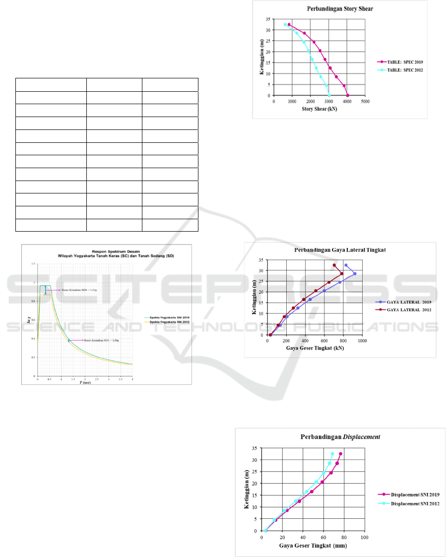
Table 1: Spectra Parameters.
PARAMETER SNI 2019 SNI 2012
Ss 1.209 1.304
S1 0.530 0.471
Fa 1.200 1.000
Fv 1.470 1.529
Sms 1.451 1.304
Sm1 0.779 0.720
Sds 0.967 0.869
Sd1 0.520 0.480
T0 0.107 0.110
Ts 0.537 0.552
TL 8 8
Figure 3: Comparison of Yogyakarta Regional Design
Spectrum Curves.
4.3 Relation of Static Earthquake
Load – Dynamic
Based on SNI 1726: 2012, the dynamic earthquake
load must not be less than 85% of the static
earthquake load, or in other words VDYNAMIC ≥
0.85VSTATIC, if these conditions are not met then
the dynamic earthquake load must be multiplied by a
scale factor of. While SNI 1726: 2019 dynamic
earthquake load must not be less than 100% static
earthquake load, or in other words VDYNAMIC /
VSTATIC, if these conditions are not met then the
dynamic earthquake load must be multiplied by a
scale factor of.
4.3.1 Sliding Force
Figure 4: Story Shear graphics on hard and medium soils.
Building Lateral Style
The lateral earthquake force of the design of each
floor is obtained from the shear force of each floor of
the design results of the previous analysis. The
earthquake force on a floor is the difference between
the shear forces between the floors, so that the
respective values can be seen in the table below.
Figure 5: Lateral Force.
4.3.2 Image Lateral Force
Service Limit Performance Analysis
Figure 6: Displacement.
iCAST-ES 2022 - International Conference on Applied Science and Technology on Engineering Science
150
4.4 Design Control
Structural design control is carried out on checking
the deviation limits between floors as regulated in
articles 7.8.6 and 7.12.1 as well as the stability due to
the P-Delta effect regulated in Indonesian article
7.8.7.
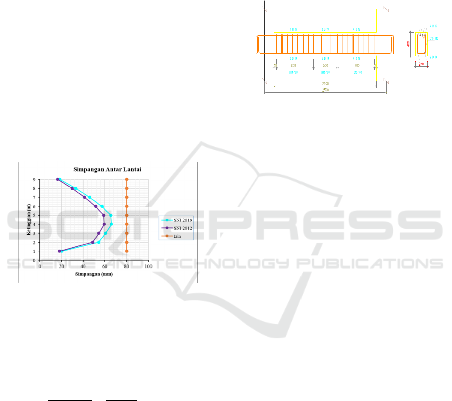
4.4.1 Deviation Between Floors of SNI 1726:
2019
Based on article 7.12.1 table 16 Deviation between
floors of SNI 1726: 2012 permit for types of
structures that fall into all other types of structures
and are in risk category II, the deviation limit between
the permit floors is 0.020 hsx. Meanwhile, SNI 1726:
2019 did not change the deviation limit between
levels from the previous SNI 2012. Based on the
results of the analysis of Etabs v.19.0.0 software, the
displacement and deviation between floors in the x
direction are obtained as shown in the table below.
Figure 7: Allowable deviation between levels.
The shear design of the beam is planned based on
the maximum flexural strength of the beam (Mpr) that
occurs in the plastic area of the beam, namely at the
critical section with a distance of 2h from the edge of
the beam. The factor shear force on the face of the
load is calculated as follows.
Ve
M
pr1
+
M
pr3
l
n
േ
Wu x ln
2
(3)
Where :
Ve = Shear force due to the plastic hinge at the ends
of the beam (kN).
Mpr = the possible bending strength of a structural
component (kNm).
Wu = Factored shear force
(kN). Ln = Length of clear span (m).
From the calculation results, the main
reinforcement is 4D19 for the upper reinforcement
and 2D19 for the lower reinforcement in the right
pedestal area, meanwhile in the left support area
4D19 is used for the top reinforcement and 2D19 for
the lower reinforcement, the middle span area uses
the 2D19 for the top and 4D19 for the lower
reinforcement. . Sengkang D10-100 mm for supports
and D10-150 for fields on beam dimensions 250 mm
x 450 mm. For details on reinforcement can be seen
in the following image.
Figure 8: Main beam reinforcement details.
SNI 2847-2013 article 23.4 explains that for
structural components in the calculation of the special
moment-bearing frame system (SRPMK), which
bears the force due to earthquake loads and receives
a factored axial load greater than 0.1., the components
of the structural elements must meet the following
requirements: first, the structural components bear a
factored axial compressive force of not less than
0.1.Ag.fc '. Second, the dimension of the shortest side
is not less than 300 mm. And third, the ratio of the
dimensions of the shortest section to the
perpendicular side is not less than 0.40. The column
is planned to be stronger than the beam (strong
column weak beam). Columns are viewed against the
wobbling or non-swaying portals, as well as for
wandering. The flexural strength of the column is
calculated based on the design of the strong column
weak beam capacity, which is as follows.
M
c
≥ 1,2 M
g
(4)
Where:
M
c
= Column nominal moment.
M
g
= Nominal moment of block.
SRPMK column shear strength occurs plastic
hinge joints at the ends of the beams that meet the
column. In column planning, the shear force is
obtained by adding the Mpr of the upper column with
the Mpr of the lower column divided by the net height
of the column. The shear force does not need to be
taken to be greater than the design shear force of the
beam-column connection strength based on the Mpr
of the beam, and cannot be less than the factored shear
force from the structural analysis. The column plan
shear force diagram can be seen in the following
Figure:
Study on the Application of Earthquake Resistant Standards (SNI 1726: 2019) Against Building in Yogyakarta City
151

Figure 9: Column Shift Style Diagram.
From the calculations, we get the main reinforcement
36D22 and stirrup 4D10-100 for the support area and
4D10-150 for the field area. Details of column
reinforcement can be seen in the following Image.
Figure 10: Column Reinforcement Details.
4.5 Beam-Column Relationships
The beam-column connection or beam-column joint
has a very important role in the planning of high-rise
building structures with the Special Moment Bearer
Frame System (SRPMK). This is because the joints
that connect the beam to the column will very often
receive the force generated by the beam and column
simultaneously. This can cause the joint that connects
the beam and column to become weak and collapse
quickly. Therefore, restraint reinforcement is needed
to be able to accept and distribute the forces generated
by beams and columns, so that the SRPMK concept
is fulfilled. We can see the freebody diagram of the
style in the following picture.
Figure 11: Forces Acting on the Beam-Column
Relationship.
From the calculation results, the D10-150 count
was designed. Details of beam-column reinforcement
can be seen in Image 11 below.
Figure 12: Details of Beam-Column Relationships.
5 CONCLUSION
From the results of the review of the City Hall Tower
building structure, in terms of the effect of changes in
design earthquake loads (changes from SNI 1726:
2012 to SNI 1726: 2019), several conclusions can be
drawn as follows:
Statically equivalent, the seismic
bottom shear force has increased quite significantly,
namely 3,572,917 kN (SNI 2012) for the x and y
directions, to 4,050.72 kN (SNI 2019), or an increase
of 113,373% in the x and y. From the results of
dynamic analysis with the analysis method of the
2012 SNI response spectrum, the seismic base shear
force is 3,036.98 kN for both x and y directions, while
the results of SNI 2019 obtained a seismic base shear
force of 4,050,720 kN for the x and y. There was an
increase in the basic dynamic shear force of 133.38%
in the x and y directions. The results of the
examination of the deviation between floors, both
according to SNI 2012 and SNI 2019 regulations, the
structure of the Yogyakarta City Hall Tower building
still shows a safe level of performance. In the next
control analysis, namely checking Stability of the
building / P-Delta effect, the structure of the City Hall
Tower building is still in stable condition.
Acceleration of rocks in the short period in
Yogyakarta City has an acceleration decrease of
0.93g. While the acceleration of the rock in a period
of 1 second, there was an increase in the acceleration
of 1.12g. The design response spectrum between SNI
2012 and the 2017 Earthquake Map in the city of
Yogyakarta, there was an acceleration increase ratio
of 1.20g. While the acceleration in the period of 1
second, there is also an increase of 1.30g. This shows
iCAST-ES 2022 - International Conference on Applied Science and Technology on Engineering Science
152

that the earthquake load of SNI 1726: 2019 is more
influential than SNI 1726: 2012.
ACKNOWLEDGEMENTS
Alhamdulillah, all praises be to Allah that has given
all the pleasures. With the gifts and conveniences that
Allah gave, so researchers can be completed this
research. Thanks to master in Civil Engineering,
Faculty of Engineering Sultan Agung Islamic
University Semarang and all parties for the
participation and support.
REFERENCES
Chock, G. Y. (2016). Design for tsunami loads and effects
in the ASCE 7-16 standard. Journal of Structural
Engineering, 142(11), 04016093.
Nasional, B. S. (2012). Tata cara perencanaan ketahanan
gempa untuk struktur bangunan gedung dan non
gedung. Sni, 1726, 2012.
Nurjaman, H. N. Beban desain minimum dan kriteria terkait
untuk bangunan gedung dan struktur lain. BSN.
Indonesia, S. N. (2013). Persyaratan beton struktural untuk
bangunan gedung. SNI, 2847, 2013.
Siswanto, A. B. (2018). Kriteria dasar perencanaan struktur
bangunan tahan gempa. Jurnal Teknik Sipil, 11, 59-72.
Hastono, B., & Syamsudin, R. (2018). Perbandingan
Ketahanan Gempa SNI 03-1726-2002 & SNI 03-1726-
2012 Pada Perencanaan Bangunan Gedung Di Kota
Aceh. Ge-STRAM: Jurnal Perencanaan dan Rekayasa
Sipil, 1(1), 1-7.
Hardianto, W., Hanintyo, A. B., Indarto, H., & Nurhuda, I.
(2014). Perencanaan Struktur Gedung Kuliah di
Yogyakart. J. Karya Tek. Sipil, 3(1), 1056-1068.
Farlianti, S., & Sapta, S. (2020). Perhitungan Respon
Spektra Percepatan Gempa Kota Palembang
Berdasarkan SNI 1726; 2019 Sebagai Revisi Terhadap
SNI 1726; 2012. TEKNIKA: Jurnal Teknik, 6(2), 167-
177.
Study on the Application of Earthquake Resistant Standards (SNI 1726: 2019) Against Building in Yogyakarta City
153
