
The Method for Generating High Resolution Images in Low Light
Conditions
Junfeng Shi
*
, Qinghua Zhu, Youlan Wu, Zhifang Cai and Dongqin Hu
The School of Electronic and Information Engineering, Beijing Polytechnic, Beijing, China
Keywords: Infrared Image, Image Fusion, Electro-Optic Image.
Abstract: This method through fusion of edges detected in an electro-optic image with a corresponding transformed
infrared image and the original infrared image. Alternatively, the method generates high resolution images in
low light conditions when an electro-optic image is not available by edge detection of an infrared image,
transformation of the infrared image and fusion of the transformed infrared image with the edges detected in
the infrared image. The method is particularly useful for night vision applications.
1 INTRODUCTION
Electro-optic ("EO") imaging techniques are capable
of achieving high-resolution images when the object
to be imaged is illuminated by adequate light of an
appropriate wavelength, as during the day. Electro-
optic imaging devices are less useful at night or in
other low light conditions. Infrared ("IR") imaging
technology is dependent upon heat emitted by the ob-
ject to be imaged and is not dependent on incident
light reflected by the object. Infrared imaging tech-
niques hence can be used in conditions of complete
darkness. Infrared imaging is inherently of lower res-
olution that electro-optic imaging and suffers from
noise in the signal. Infrared imaging is also poor at
discriminating between object having a similar tem-
perature. Night vision systems are known. For exam-
ple, it is shown that a night vision system in which
edge detection is applied to an infrared image and the
detected edges fused with an image-intensified visi-
ble light image (U.S. Patent 7,864,432 to Ottney is-
sued 2011). See literature (U.S. Patent 7,864,432 to
Ottney issued 2007, U.S. Patent 7,864,432 to Ottney
issued 2003) for the same disclosure and teaches a
head worn night vision system include image intensi-
fiers operating in the near infrared. In the literature,
see "Cognitive Image Fusion and Assessment," Alex-
ander Teot, chapter of Image Fusion, edited by
Osamu Ukimura (Ruzic, Pizurica 2012). See also
"Experimental Tests of Image Fusion for Night Vi-
sion," Y. Chen and R. Blum, available (huang,
Netravali 2012, Huang, Man, Lawrence 2012). Cop-
ies of the Teot and Chen articles are attached to this
provisional application and incorporated by reference
herein. Using current imaging techniques, it is not
possible to distinguish the edges of objects in low
light conditions, such as at night, where the objects
have a similar temperature and a similar background,
or tiny parts of any objects.
2 THE RESEARCH METHOD
2.1 First Innovative Method
The first method involves the following steps: (a)
capturing an electro-optic image of objects; (b) pro-
cessing the electro-optic image by applying edge de-
tection technology to detect the edges within the elec-
tro-optic image; (c) collecting an infrared image of
objects corresponding to the electro-optic image; (d)
transforming the infrared image by applying a Wiener
filter or an inverse filter based on the point spread
function of the thermal imaging method; (e) register-
ing the infrared and electro-optic images to match
features of one image with the other; and (f) fusing
the transformed infrared image and the detected edges
of the electro-optic image to create a composite im-
age. The composite image features better resolution
among objects than the original infrared image.
572
Shi, J., Zhu, Q., Wu, Y., Cai, Z. and Hu, D.
The Method for Generating High Resolution Images in Low Light Conditions.
DOI: 10.5220/0011752200003607
In Proceedings of the 1st International Conference on Public Management, Digital Economy and Internet Technology (ICPDI 2022), pages 572-577
ISBN: 978-989-758-620-0
Copyright
c
2023 by SCITEPRESS – Science and Technology Publications, Lda. Under CC license (CC BY-NC-ND 4.0)

The step of capturing the electro-optic image may
occur at a time different from the time that the infra-
red image is captured. For example, the electro-optic
image may be captured during daylight hours so that
the object to be imaged is adequately illuminated to
create a high resolution, low noise image having read-
ily identifiable edges. The corresponding infrared im-
age may be captured during periods of low light when
the electro-optic detector is not effective.
The step of transforming the IR image may occur
in any of several ways, either alone or in combination.
For example, the IR image may be transformed by ap-
plying an inverse filter using a Fourier transform
based on the theoretical point spread function ("PSF")
of the infrared detector. The IR image transformation
may be based on the measured, rather than theoreti-
cal, point spread function for the infrared imaging
system. The inverse filtering process utilizing either
the theoretical or measured point spread function of
the IR imaging system reduces the noise in the image
and makes the transformed infrared image look
“sharper” than the original one. The IR image may be
filtered by applying the Wiener filter as an alternative
to transform the IR image if noise is not neglectable.
The inverse filter is a special case of the more general
Wiener filter.
The step of edge detection of the EO image in-
volves applying an edge detection algorithm to the
EO image. The resulting edge-detected image com-
prises the detected edges. The step of registering the
transformed IR image and the edge-detected EO im-
age may be as simple or as complex as the data re-
quire and involves the identification and matching of
corresponding features on the IR and EO images. The
step of blending the edge-detected EO image and the
transformed IR image involves overlaying the de-
tected edges on the corresponding locations of the
transformed IR image. The blending step may include
blending of the original, un-transformed IR image
with the transformed IR image and the detected
edges.
2.2 B. Second Innovative Method
The method of the method can generate images of im-
proved resolution when only an IR image and no cor-
responding EO image is available. In this second
method, the steps include (a) capturing an IR image,
(b) transforming the IR image by applying a Wiener
filter or an inverse filter using a Fourier transform
based on either a theoretical point spread function or
a measured point spread function of the infrared im-
age, (c) applying an edge detection algorithm to de-
tect the edges in the IR image, and (d) blending the
edge-detected IR image, the original IR image and the
transformed IR image to form a fused IR image.
3 METHOD DESCRIPTION
Figs. 1 and 2 are schematic diagrams illustrating the
first method of the method. Fig. 1 shows the flow of
information in the first method while Fig. 2 shows the
method of the first method. As shown by Figs. 1 and
2, an EO sensor captures an EO image. An IR sensor
captures an IO image, either at the same or at a differ-
ent time from the capture of the EO image. The IR
and EO images are registered to match features of the
IR and EO images for use in blending the processed
images. The EO image is analyzed using an edge de-
tection algorithm to detect differences in hue, color or
intensity that may indicate an edge of an object. The
result of the edge detection is an edge-detected EO
image comprising the detected edges. The other in-
formation in the original image generally is omitted
in the edge-detected EO image. As indicated by Fig.
7, the edgedetected EO image may be further pro-
cessed by applying a small-size low pass filter to the
edgedetected image. The IR image is transformed us-
ing either a Wiener filter or an inverse filter based on
the point spread function of the IR sensor. The inverse
filter is a particular application of the Wiener filter
and comprises transforming the IR image using the
point spread function of the IR sensor. The selection
of either the Wiener filter or the inverse filter may de-
pend upon the noise level in the original IR image. If
the original IR image has a high noise level, then the
Wiener filter will be adopted to reduce that noise
level. If the original IR image has little or no noise,
then the inverse filter is the filter of choice. The
method of the method may be configured to select the
appropriate filter based on the noise level of the orig-
inal IR image. The point spread function of the IR
sensor applied in either the Wiener filter or the in-
verse filter may be either a theoretical point spread
function or a point spread function determined by
measurement. As an optional step, the transformed IR
image and the edge-detected image may be registered
to match the detected edges in the edge-detected im-
age to the edges shown by the transformed IR image.
The edge-detected EO image, the transformed IR
image, and the original, un-transformed IR image
The Method for Generating High Resolution Images in Low Light Conditions
573

Figure 1: Flow of information(self-created).
Figure 2: Flow chart(self-created).
then are blended to define a fused image. The result-
ing fused image demonstrates a better resolution
among objects shown by the images than either the IR
image or the EO image alone. For further explanation,
see the attachments.
Figs. 3-5 illustrate the second method of the
method. The second method applies when an IR im-
age, but not an EO image, is to be processed. Fig. 3
illustrates the information flow of the second method.
Fig. 4 illustrates the method of the method. From
Figs. 3 and 4, an IR sensor captures an IR image. The
IR image is processed along two different paths and
the results of the processing are blended to form a
fused image. In the first method, an edge detection al-
gorithm is applied to the IR image to determine an
edge-detected image. The edge-detected image com-
prises the detected edges and generally does not in-
clude the other information in the original IR image.
In the second path, the original IR image is trans-
formed by applying either a Wiener filter based or an
ICPDI 2022 - International Conference on Public Management, Digital Economy and Internet Technology
574
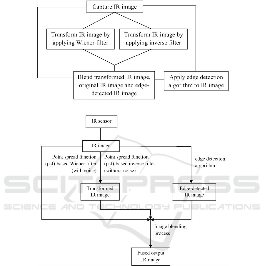
Figure 3: Flow chart(self-created).
Figure 4: Flow chart(self-created).
inverse filter comprising a Fourier transform based on
the point spread function of the IR sensor. The step of
transforming the IR image is conducted as indicated
above for the first method. The transformed IR image
is then blended with the edge-detected IR image and
the original IR image to define a fused output image.
The fused output image demonstrates a better resolu-
tion among objects shown by the images than the IR
image alone. Fig. 5 also relates to the second method
and illustrates that the filtering of the IR image shown
by Figs. 3 and 4 may be based on either a theoretical
point spread function of the IR sensor or may be based
on an actual measured point spread function of the IR
sensor.
Fig. 6 illustrates the method for the first method
of the method. The method comprises a microproces-
sor operably connected to the IR sensor, the EO sen-
sor, a computer memory and a computer display. The
method receives data from the IR sensor defining the
IR image and data from the EO sensor defining the
EO image. The microprocessor is configured to re-
ceive and manipulate the data by programming in the
computer memory. The microprocessor is configured
to perform each of the steps described above or as
The Method for Generating High Resolution Images in Low Light Conditions
575
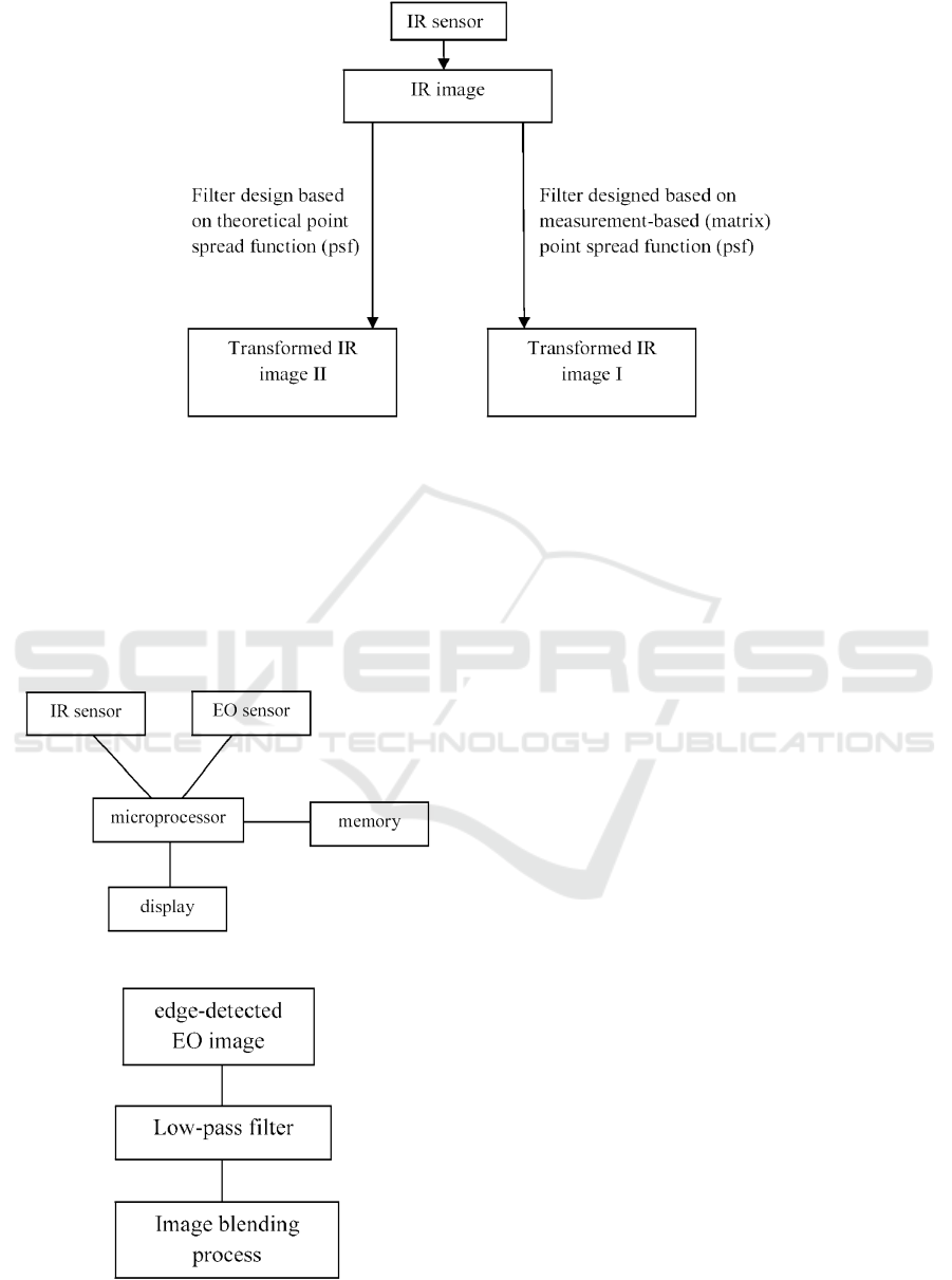
Figure 5: Flow chart(self-created).
shown in the attachments, resulting in the fused im-
age. The fused image is displayed to the user on a dis-
play. Also from Fig. 6, the method of the method for
the second method of the method has characteristics
similar those shown, except that the microprocessor
does not receive or does not process EO image data
from the EO sensor. The microprocessor is otherwise
configured to perform each of the steps set forth
Figure 6: Flow chart(self-created).
Figure 7: Flow chart(self-created).
above or in the attachments for the second method,
resulting in a fused image. The display is configured
to display the fused image to the user. Fig. 7 illus-
trates an additional filtering step that may be applied
to an edge-detected image. The additional step is
passing the edge-detected image through a small-size
low pass filter for the purpose of smoothing the de-
tected edges. The small-size low pass filter, for exam-
ple a 2 by 2 average filter as known in the art, allows
the detected edges to seamlessly match the objects
shown by the original IR image and transformed IR
image. The low pass filter must be small in size to
prevent loss of the edge information in the edge-de-
tected image. While Fig. 7 illustrates the additional
filtering step as applied in the first method of the
method as shown by Figs. 1 and 2, the technique also
may be applied to the edge-detected IR image in the
second method, shown by Figs. 3
4 CONCLUSION
This paper proposes a method of image fusion, with
combination of infrared image and the original infra-
red image. Through the above analysis, we can obtain
some useful results: the proposed method generates
high resolution images in low light conditions, partic-
ularly, edge detection of an infrared image is not
available for electro-optic image.
In the future study, our works are mainly focus on
multimedia video processing that employ image fu-
sion method proposed in this paper.
ICPDI 2022 - International Conference on Public Management, Digital Economy and Internet Technology
576

REFERENCES
U.S. Patent 7,864,432 to Ottney issued January 4, 2011.
U.S. Patent 7,307,793 to Ottney issued December 11, 2007
U.S. Patent 6,560,029 to Dobbie issued May 6, 2003
"Fusing electro-optic and infrared signals for high resolu-
tion night images," SPIE Image Processing: Algorithms
and Systems X; and Parallel Processing for Imaging
Applications II, Tijana Ruzic; Aleksandra Pizurica:
February 5, 2012.
"Improved fusing infrared and electro-optic signals for
high-resolution night images," Proceedings of SPIE,
Volume 8355 (1), Xiaopeng huang; Ravi Netravali,
May 11, 2012.
Multi-Sensor Fusion of Infrared and Electro-Optic Signals
for High Resolution Night Images, Xiaopeng Huang;
Hong Man;Victor Lawrence, 2012, 12, 10326-10338.
The Method for Generating High Resolution Images in Low Light Conditions
577
