
The Design of DC Motor for Robotic Hand to Install Strain Clamp
Cover on Live Line Voltage 20,000 Volt
I Wayan Jondra, I Gede Suputra Widharma, I Gede Nyoman Suta Waisnawa,
Ni Putu Susri Apriliana Iriani and Ni Made Amustini
Electrical Department, Politeknik Negeri Bali, Jalan Kampus Bukit Jimbaran, Kabupaten Badung, Indonesia
Keywords: Motor, Mechanism, Robot.
Abstract: Economic activities that are: office activities, shops, factories/industries (small and large scale), malls,
households, all of them need electricity. Electricity is the foundation sector for achieving development goals,
such as creating job opportunities, increasing national income, changing the economic structure and
improving people's welfare. The distribution reliability index is calculated by value of SAIDI (System
Average Interruption Duration Index) and SAIFI (System Average Interruption Frequency Index). Thus, the
value of SAIDI and SAIFI must be minimized the outage as small as possible. To minimize planned power
outages or disturbances, robotic hands are needed to install distribution line accessories such as Strain Clamp
Cover on Live Line Condition. The Analysis finding the force to close the hand robot, need 8.23 Newton was
needed with a distance between the load and the hinge that are 0.262 meters. The electric motor is installed at
a distance of 0.088 meters from the hinge, required DC motor with power more than 24.5 watts. After
matching to the specifications of the existing motors, found a DC motor with performance 48 Watt, 12 Volt,
4 amperes. To control the DC motor, it is done with a 5 Amp capacity driver at a voltage of 12 Volts. The test
results found that the maximum current is 6.6 Amperes, without any failure of operation on the motor and
driver. This 48 watt DC motor supported by 5 amperes DC Controller that are available to drive the robotic
hand.
1 INTRODUCTION
Economic activities that are: office activities, shops,
factories/industries (small and large scale), malls,
households, all of them need electricity. The growth
in electrical energy as happened in China is
dominated by consumer growth in the housing sector
(Zhaoguang et al, 2014). Indonesia is also growing in
the use of electrical energy which is quite high.
Electricity is the foundation sector for achieving
development goals, such as creating job
opportunities, increasing national income, changing
the economic structure and improving people's
welfare (Santika, 2020). The distribution reliability
system has a vital need to keep electricity on for 24
hours a day. Thus, the value of SAIDI and SAIFI
must be minimized as small as possible.
The distribution reliability index is calculated by
value of SAIDI (System Average Interupption
Duration Index) and SAIFI (System Average
Interupption Frequency Index) as reliability
indicators. In most areas in Indonesia PLN has not
been able to meet SAIDI and SAIFI standards. To
minimize planned power outages or disturbances,
robotic hands are needed to install distribution line
accessories such as Strain Clamp Cover on Live Line
Condition.
For this robotic hand driver, a driving mechanic is
needed. Thus, this study discusses the driving
mechanics needed for this robotic hand driver. It takes
a mechanical drive with a low speed but has a hard
moment. The use of a speed reducer gearbox with a
speed ratio of 20:1 will result in an increase in force
of 1:20 (Sobhan, 2015). For the robot hand driver, a
DC electric motor will also be used which is equipped
with a gearbox. The problem is how much motor
power is needed and how to control the DC motor.
2 RESEARCH METHODE
2.1 Research Approach and Concept
This quantitative research approach study to find the
design of a electro mechanism to drive the robotic
232
Jondra, I., Widharma, I., Waisnawa, I., Iriani, N. and Amustini, N.
The Design of DC Motor for Robotic Hand to Install Strain Clamp Cover on Live Line Voltage 20,000 Volt.
DOI: 10.5220/0011756100003575
In Proceedings of the 5th International Conference on Applied Science and Technology on Engineering Science (iCAST-ES 2022), pages 232-238
ISBN: 978-989-758-619-4; ISSN: 2975-8246
Copyright © 2023 by SCITEPRESS – Science and Technology Publications, Lda. Under CC license (CC BY-NC-ND 4.0)

hands. This electro mechanism will move the robot's
hand to open and close then press the cover of the
strain clamp insulator, until it closes perfectly.
The concept of this research is to convert the
required mechanical compressive force at the end of
the pressure point into the required electric motor
power. Based on the power of the electric motor
needed, research on the needs of the motor driver and
microcontroller is needed.
The test of compressive force required the based
load point is carried out by giving the load at the
based load point gradually. The weight of the load at
the based load point in the time of the robot hand
closes the cover strain clamp completely, the weight
of the load is recorded and multiplied by the
acceleration / gravity of the earth as the required
compressive force. The performance test of the DC
motor and control on the robotic hand is done by
observed the voltage and current changes in the DC
motor every 4 seconds until the robotic hand closes
completely.
2.2 Total Sample
This research was conducted with 100% sample that
are 3 set of robotic hands, the collection was carried
out with a total of 30 data. To obtain these 30 data, it
was done by loading the water load repeatedly for 10
time for each sample until the cover strain clamp
closed completely. The total of the water weight plus
the container weight multiplied by the gravitational
force of the earth is recorded as the force required to
close the robotic hand.
Data on the test result of the performance of the
DC motor and control is done by observed voltage
and current in the DC motor every 4 seconds until the
robotic hand closes completely. So that for one
observation, 13 data were obtained for each sample
because the working time was 52 seconds, the total
data became 39 data for the three samples.
2.3 Variable Operational Definition
The focus of this study to observing the magnitude of
the indicators of this research, that are: force, voltage,
current, power and battery capacity. Voltage is
amount in volt of potential test voltage between two
terminal of motor DC. The current is amount in
ampere of electron flow from battery to the motor
DC. Power in watt or newton yang calculated to real
load on the base point of load. Battery capacity was
calculated to the battery insertion in to the robotic
hands.
2.4 Data Analysis
Data obtained from the test results and nameplate are
processed quantitatively. Data processed
mathematically and statistically by finding the data
variation on the step on each water filling. The data
are processed mathematically to obtain the voltage,
current and power at the initial of the test. The output
mathematically data is processed trough statistically
to obtain the average data, data sequence, which is
also displayed graphically.
3 FORCE, DC MOTOR, DRIVER
AND BATTERY
3.1 Force
Newton’s second law of motion points out the
magnitude of force when velocity of body move in
force is proportional to impressed force.
Mathematically, can be describe Force was change in
velocity. That issue is now second law of motion is
based on definition of equation of force is weigh
multiple with velocity for horizontal move, and with
earth gravitation for vertical move, that are as
describe on this formula in below (Sarma, 2017)
𝐹 = 𝑀. 𝑎
(1)
The formula above can be explained that the value
of the force (F) is determined by the mass value (M)
of the object multiplied by the acceleration (a). The
unit of force is measured in Newtons, the unit of mass
of an object is measured in Kg and the unit of
acceleration is measured in m/s
2
(Caldwell et al.,
2020)(Ariadi & Dinata, 2018).
3.2 DC Motor for Robotic
Direct Current Motor Trough electromagnetic
converts the direct current electrical energy to
mechanic energy(Qader, 2017). Electricity in a DC
motor is flowed into the field coil so as to produce
magnetic flux, electricity is also flowed through the
charcoal brush to the rotor coil, so that the rotor coil
produces a rotor field. The size of the mechanical
power produced by the electric motor is greatly
influenced by the size of the field coil and the rotor
coil, so that the larger the coil, the greater the current
that flows and so that the electrical power consumed
is greater, resulting in large mechanical
power(Iswanto et al., 2020).
The Design of DC Motor for Robotic Hand to Install Strain Clamp Cover on Live Line Voltage 20,000 Volt
233
To reverse the rotation of the rotor can be done by
reversing the incoming current to the DC motor
terminal, which was originally positive connected to
a negative voltage source, and vice versa the negative
one was connected to a positive voltage
source(Purnata et al., 2022). This reversal of the
motor terminals will result in the reverse direction of
the current entering the motor, so that the motor
rotation is reversed. This phenomenon occurs in
accordance with the law of the left hand which reads:
the index finger indicates the direction of the current,
the thumb indicates the direction of the pulsation, and
the other three fingers indicate the direction of the
field.
3.3 Driver
There are many ways to control a DC motor. DC
motors can be controlled by switches, contactors,
relay, or electronic switches such as SCR and so on.
The DC motor controller must have a capacity greater
than the nominal current of the DC motor. Starting
current affect to driving torque can overcome the load
torque from the rolling resistance, the motor will
already start rotating(Qader, 2017).
L298 Motor Driver is a module that is often used
to control DC motors or stepper motor(Peerzada et
al., 2021). By using the L298 Motor Driver easily
control both the speed and direction of rotation of 2
motors at once. The L298 Motor Driver is designed
using the L298 Dual H-Bridge IC. The Motor Driver
contains H-Bride logic gates which are already very
popular in the electronics world as controlling the
speed and direction of motor rotation.
3.4 Battery
Batteries is energy storage for portable electrical
equipment, as well as robotic. Batteries are the critical
component for portable electric robotic live, even if
they are not connected to electric energy source.
Lithium-based batteries have many advantages over
conventional batteries such as Nickel-Cadmium,
Nickel-Metalhydrate or Lead Acid (Knowles,
M.,2013). The advantages of Lithium-based batteries
are high energy density, high power density, low self-
discharge, fast charging, high mass-to-energy ratio,
no memory effect, long lasting if the charging process
is appropriate (Xiaopeng. C. et al.,2012). However,
Lithium-based batteries also have the disadvantage of
being less tolerant, so they require accurate
monitoring and protection procedures to ensure that
one of the battery cells does not overcharge, and
ensure that the battery does not overheat which can
reduce battery life (Ranjbar, A.H., et al.,2012).
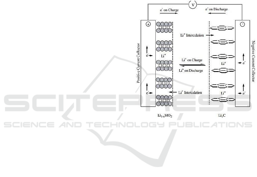
Nowadays Lithium-ion battery that is widely used
in electronic devices. The active electrode in a
Lithium-ion battery is lithium metal oxide for the
positive electrode while carbon is for the negative
electrode. This material contains a metal collector
current with a binder, usually polyvinylidene fluoride
(PVDF) or polyvinylidene fluoride-
hexafluoropropylene (PVDF-HFP) copolymer, and a
conductive diluent.
Figure 1: Electrochemical process in lithium-ion batteries.
The capacity of a battery is greatly influenced by
the quality of the material and the dimensions of the
material, so that in the same type it will appear that
the dimensions are larger for a larger battery capacity.
The capacity of the battery at a certain voltage will be
described by how much current can be stored by the
battery in ampere hours (ampere hours).
4 DC MOTOR AND CONTROL
DESIGN
4.1 DC Motor Design
The amount of DC motor power required to carry out
the robotic hand functions is influenced by the force
as the load of DC motor. The magnitude of the force
load of the DC motor (Newton) in the robotic hand is
influenced by three values, including: (1) the value of
the distance (meters) of the DC motor to the fulcrum,
(2) the value of the distance (meters) from the fulcrum
iCAST-ES 2022 - International Conference on Applied Science and Technology on Engineering Science
234
to the load point, and (3) the compressive force
(Newton) required by the load.
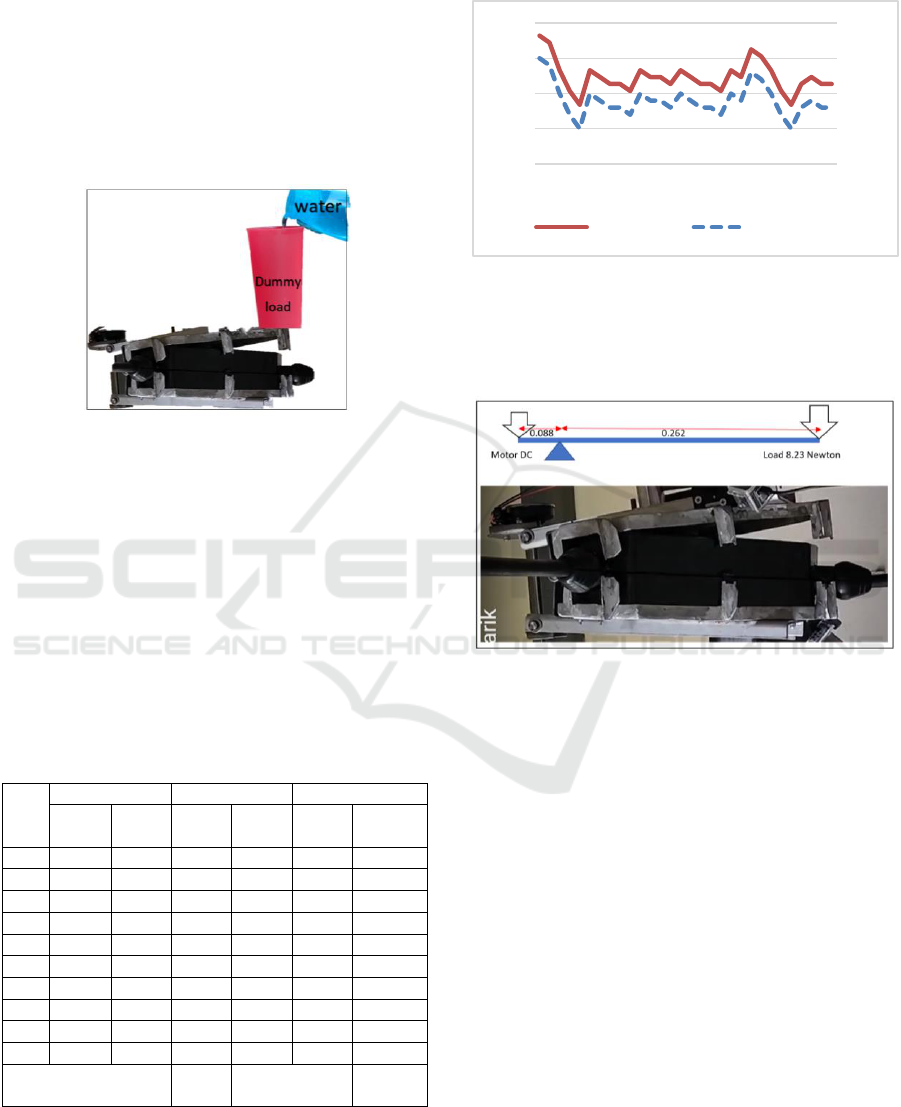
The required of compressive force of the robotic
hand to close the strain clamp cover is carried out by
tested using a dummy load by a water container. The
water container is placed at the end point of load from
the fulcrum. Water is poured into the container slowly
until the robotic hand closes to closes the strain clamp
cover. When the strain clamp cover is completely
closed, the water pouring is stopped.
Figure 2: Loading test.
The water and the container are taken from the
robotic hand to measured its weight. The weight of
the water and the container is multiplied by the earth's
gravity of 9.8 m/s2, then the value of the compressive
force required to closed the strain clamp cover
perfectly. The test results of three samples of robotic
hands, each sample was loaded 10 times, so that the
total data is 30 data were obtained. The data is
processed statistically, so the graph and the average
compressive force will be obtained. The test result
data can be shown in the table below.
Table 1: Force test result.
NO
Sample 1
Sample 2
Sample 1
Weigh
t (Kg)
Force
(N)
Weigh
t (Kg)
Force
(N)
Weigh
t (Kg)
Force
(N)
1
0.9
8.82
0.85
8.33
0.84
8.23
2
0.89
8.72
0.84
8.23
0.88
8.62
3
0.85
8.33
0.84
8.23
0.87
8.53
4
0.82
8.04
0.83
8.13
0.85
8.33
5
0.8
7.84
0.85
8.33
0.82
8.04
6
0.85
8.33
0.84
8.23
0.8
7.84
7
0.84
8.23
0.83
8.13
0.83
8.13
8
0.83
8.13
0.83
8.13
0.84
8.23
9
0.83
8.13
0.82
8.04
0.83
8.13
10
0.82
8.04
0.85
8.33
0.83
8.13
Average Weight (Kg)
0.84
Average Force
(Newton)
8.23
Based on the data at table 1, the data variation can
be describe by the chart at the figure 2 below. The
variation of the quality strain clamp cover affect to
the variation of weight of dummy load to get the
perfect closes.
Figure 3: Variation of loaded.
The placement of the DC motor and the load
point, carry out the load distributed can be explained
in the figure 3 below.
Figure 4: Robotic hand load distribution.
Like in the figure 3 can be describe (1) the value
of the distance of the DC motor to the fulcrum is
0.088 meters, (2) the value of the distance from the
fulcrum to the load point is 0.262 meters, and (3) the
required of compressive force is 8.23 Newton. Based
on this data, the DC motor power can be analysis
trough balance load principles, as describe at below.
F
1
xl
1
= F
2
x l
2
F
1
x0.008 = 8.23 x 0.262
F
1
= 8.23 x 0.262 / 0.008
F
1
= 24.5 Newton
Base on the calculation, to drive the robotic hand
the DC motor must be produce force more than 24.5
Newton, that are similar more than 24.5 watt, the
assumption is no friction loses.
Based on the calculations above, for the robotic
hand driver, a motor above 24.5 watts is needed.
Found on the market a complete DC motor gearbox,
0,75
0,8
0,85
0,9
0,95
7,00
7,50
8,00
8,50
9,00
1 3 5 7 9 111315 17 19 21232527 29
FORCE (N) WEIGTH (Kg)
The Design of DC Motor for Robotic Hand to Install Strain Clamp Cover on Live Line Voltage 20,000 Volt
235
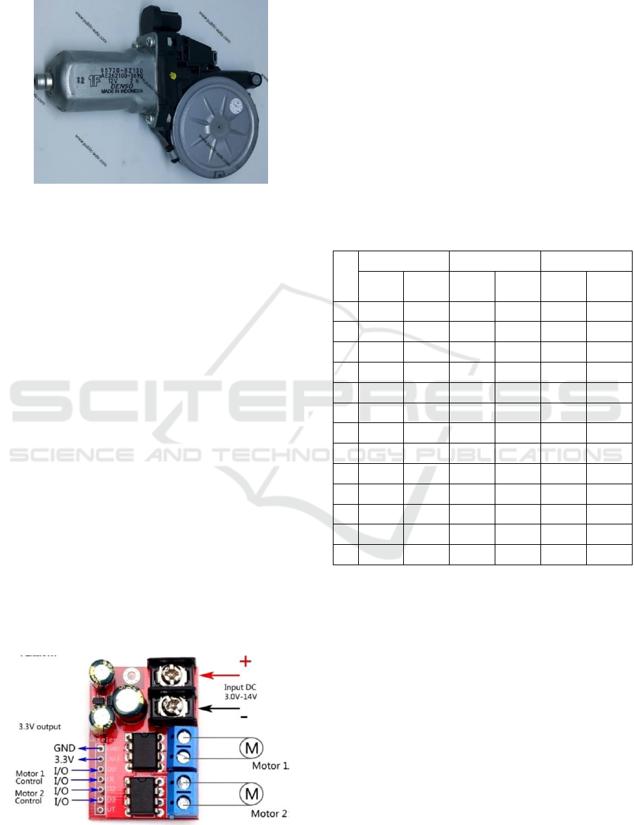
with a capacity of 48 watts, 12 volts, 4 amperes as
shown in the picture below.
Figure 5: DC motor 48 watts.
Based on the data shown in table 3 and graphs in
the figure 5, it appears that the DC motor electric
current shows an increasing trend in the process of
closing the robotic hand. The graph shows the electric
current soaring up at the end, because there is a
process of locking the strain clamp cover. The graph
also shows that the stress drops during the strain
clamp cover locking process.
4.2 Control Design
Based on the choice of the DC motor used to drive the
robotic hand, to determine the driver design, the
maximum DC motor current is calculated. The data
on the DC motor nameplate shows 12 volts of 48
watts (0.064 hp). The calculation of the maximum
motor current is calculated as below.
I = P/V
I = 48/12 = 4 Amperes
Taking the calculation results of the above, that
the nominal DC motor current is 4 amperes, the driver
to control it must have a capacity higher than 4
amperes. Searches in the market show 4 amperes
drivers which are easily available are drivers with a 5
amperes capacity, as shown in the image below.
Figure 6: DC motor controller l298.
5 RESULT AND DISCUSSION
The results of the research are shown in numbers
arranged in a table. The data from the test results are
discussed by mathematically and statistically
analysed, which is finally displayed in the form of a
graph.
5.1 Result
To drive the robotic hand, the gearbox motor is
coupled with a trapezoidal thread to propel the arm.
The performance tested of the DC motor in the
robotic hand, to determine the electric power
consumption.
Table 2: Voltage and current test result.
NO
Sample 1
Sample 2
Sample 1
Voltage
(V)
Current
(A)
Voltage
(V)
Current
(A)
Voltage
(V)
Current
(A)
1
5,3
1,34
5,4
1,35
5,2
1,38
2
9,6
1,34
9,6
1,35
9,7
1,34
3
9,7
1,7
9,8
1,7
9,8
1,7
4
9,6
1
9,7
1,2
9,6
1,23
5
9,8
1,68
9,8
1,68
9,9
1,66
6
9,6
1,9
9,6
1,9
9,6
1,9
7
9,7
1,66
9,8
1,68
9,8
1,68
8
9,5
1,7
9,5
1,7
9,6
1,65
9
9,6
1,8
9,6
1,8
9,7
1,78
10
9,5
1,79
9,4
1,81
9,5
1,78
11
9,1
2,1
9
2,3
9,2
2,26
12
9,5
2,15
9,4
2,17
9,6
2,14
13
6,5
2,69
6,7
2,66
6,6
2,68
5.2 Discussion
Observing the data in table 2, it is necessary to do
statistical processing, to find the average voltage and
current. The DC motor terminal voltage up and down
according to the magnitude of the load current at
every moment of the robotic hand closing process.
Each change in the voltage value of the three samples
is added up and then divided by three, then the
average voltage is obtained so do that for current
flowed to the DC Motors. The results of this
processing will contain 13 voltage data and 13 current
data, respectively. The data explained the
performance of DC motor to drive the robotic hands.
Through statistical processing, can be obtained the
data contained in table 3.
iCAST-ES 2022 - International Conference on Applied Science and Technology on Engineering Science
236
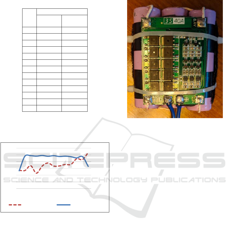
Table 3: Current and voltage analysed.
NO
Average
Voltage
(V)
Current
(A)
1
5,30
1,36
2
9,63
1,34
3
9,77
1,70
4
9,63
1,14
5
9,83
1,67
6
9,60
1,90
7
9,77
1,67
8
9,53
1,68
9
9,63
1,79
10
9,47
1,79
11
9,10
2,22
12
9,50
2,15
13
6,60
2,68
Based on the data at table 3, the data variation can
be describe by the chart at the figure 5 below. The
variation of the current affect to the voltage of battery
for every step of closing process.
Figure 7: Current trend.
The drivers l298 was installed to control DC
Motor, with a 5 amperes capacity, rated voltage 3
Volt up to 12 Volt. The choice of the l298 driver is
the right and safe choice. With a nominal current
capacity of 5 amperes, this driver will easily control a
DC motor that works with an average maximum
current of 2.8 Amperes.
To support the performance of this robotic hand,
3 pieces 4.5 Volt 3ah batteries are used, connected in
series. This battery was chosen because the DC motor
current is close to 3 amperes. With this battery, the
robotic hand will be able to operate for 45 minute
non-stop. This battery is also equipped with a battery
management system, with a nominal current
capability of 30 Amperes as shown in the image
below. Battery must be
Figure 8: Battery.
6 CONCLUSIONS
Based on the results of testing and analysis can be
concluded as follows:
1. To drive for robotic hand with 8.23 Newton
workload, are sufficient a DC motor 48 watts 12
volt.
2. Drivers at a capacity of 5 Amperes are sufficient
to controlled DC motor for a robotic hand with
a maximum working current of 2.98 Amperes.
3. The battery 12 volt, with a capacity of 3 ah, is
enough to supply 75% of its capacity to a DC
motor with a maximum operating time of 45
minutes non-stop.
ACKNOWLEDGEMENTS
This research was funded by Lembaga Pengelola
Dana Pendidikan dan Direktorat Jenderal Pendidikan
Vokasi Kementerian Pendidikan, Kebudayaan, Riset,
dan Teknologi Year 2021. We thank Project
Management Office of Domestic Vocational
Higher Education Program Implementation of the
Applied Scientific Research in 2021 for his support to
this research..
0,00
2,00
4,00
6,00
8,00
10,00
12,00
0,00
0,50
1,00
1,50
2,00
2,50
3,00
1 2 3 4 5 6 7 8 9 10 11 12 13
CURRENT (AMP) VOLTAGE (VOLT)
The Design of DC Motor for Robotic Hand to Install Strain Clamp Cover on Live Line Voltage 20,000 Volt
237

REFERENCES
Ariadi, P., & Dinata, C. (2018). Students’ Mental Model
About Newton’ S Third Law in Indonesia: Analysis and
Suggestion To Overcome It. Unnes Science Education
Journal (USEJ), 7(2), 146–155.
Caldwell, G. E., Robertson, D. G. E., & Whittlesey, S. N.
(2020). Forces and Their Measurement. In Research
Methods in Biomechanics (Issue March).
https://doi.org/10.5040/9781492595809.ch-004
Knowles, M. (2013). Through-life management of electric
vehicles. International through-life engineering
services conference, Procedia CIRP 11 (2013) 260 –
265 2nd.
Iswanto, Ma’arif, A., Puriyanto, R. D., Raharja, N. M., &
Rahmadhia, S. N. (2020). Arduino Embedded Control
System of DC Motor Using Proportional Integral
Derivative. International Journal of Control and
Automation, 13(4), 658–667.
Peerzada, P., Larika, W. H., & Mahar, A. A. (2021). DC
Motor Speed Control Through Arduino andL298N
Motor Driver Using PID Controller. International
Journal of Electrical Engineering & Emerging
Technology, 04(2), 21–24.
Purnata, H., Ramadan, S., Hidayat, M. A., & Maulana, I.
(2022). PID Control Schematic Design for Omni-
directional Wheel Mobile Robot Cilacap State of
Polytechnic. 12(2), 89–94.
Qader, M. R. (2017). Identifying the Optimal Controller
Strategy for DC Motors. IAES International Journal of
Robotics and Automation (IJRA), 6(4), 252.
https://doi.org/10.11591/ijra.v6i4.pp252-268
Ranjbar, A.H., Anahita Banei, Amir Khoobroo, and Babak
Fahimi. (2012) Online estimation of state of charge in
Li-Ion batteries using implse respone concept. IEEE
Transactions on Smart Grid, Vol. 3, No. 1. March 2012.
Santika Wayan G. TaniaUrme, elizSimseka, Parisa
A.Bahri, and M.Anisuzzaman. (2020) An assessment of
energy policy impacts on achieving Sustainable
Development Goal 7 in Indonesia. International Energy
Initiative. Volume 59, December 2020, Pages 33-48.
Published by Elsevier Inc. All rights reserved.
https://www.sciencedirect.com/science/article/pii/S097
3082620302921.
Sarma, A. (2017). TECHNOLOGY. International Journal
of Engineering Sciences & Research Technology,
6(12), 57–79
Sobhan, P. (2015). Design and Assembly of Worm Gear
Reducer. Global Journal For Research Analysis,
Volume-4, Issue-4, April-2015 • ISSN No 2277 - 8160
Xiaopeng. C., Weixiang Shen, Thanks Tu VO, Zhenwei
Caoi, and Ajay Kapoor. (2012). An overview of
lithium-ion batteries for electric vehicles. International
power & energy conference, December 2012.
Zhaoguang Hu, Xiandong Tan and Zhaoyuan Xu. (2014).
A Review of china’s economic development and
electricity consumption, An Exploration into China's
Economic Development and Electricity Demand by the
Year 2050. Cambridge: Elsevier Inc.
iCAST-ES 2022 - International Conference on Applied Science and Technology on Engineering Science
238
