
The Design Prime Mover for Mechanical Hand Installer Pull
Clamp Isolator
I Gede Nyoman Suta Waisnawa
a
, I Wayan Jondra
b
, I Gede Suputra Widharma
c
,
I Komang Kantun, I Putu Agus Haryawan and I Dewa Made Haruna Putra
Mechanical Engineering Department, Politeknik Negeri Bali, Jalan Kampus Bukit Jimbaran, Kabupaten Badung,
Indonesia
agusharyawan08@gmail.com, Dewaharuna@gmail.com
Keywords: Electric Motor, Mechanical Hand, Isolator, Efective, Times.
Abstract: PLN has not been able to meet the SAIDI (System Avarage Interupption Duration Index) and SAIFI (System
Avarage Interupption Frequency Index) standards. One of the causes of the non-fulfillment of SAIDI and
SAIFI standards in Indonesia is external disturbances, namely disturbances caused by nature or outside the
system, for example trees that are towering up to touch the connection point so as to cause a short circuit. The
presence of tekep insulators gives hope to PLN to overcome natural external disturbances caused by trees,
animals and so on.The previous installation of the insulator is done by cutting off the electricity in the network
cable. The power outage during the installation of the insulator is certainly detrimental to the customer. This
condition gave rise to the idea of making mechanical aids for the installation of insulators to make installation
easier without breaking the electricity supply to the network cable. The components purchased include an
electric motor as a driving force, a screw transmission. While the components made are pressure plates, drive
arms, hinges, motor mounts, clutches, and locking axles.The results of tests carried out by installing an
insulator using a mechanical hand on the cable connection on the power pole. The installation of the insulator
plug by mechanical hand was tested on 3 connections and carried out 5 times on 1 connection on the power
pole. The test results of installing an insulator on 1 connection using a mechanical hand obtained an average
time of 8 minutes 40 seconds.
1 INTRODUCTION
Economic activities that are: office activities, shops,
factories/industries (small and large scale), malls,
households, all of them need electricity. The growth
in electrical energy as happened in China is
dominated by consumer growth in the housing sector
(Zhaoguang, Xiandong, & Zhaoyuan, 2014).
Indonesia is also growing in the use of electrical
energy which is quite high. Electricity is the
foundation sector for achieving development goals,
such as creating job opportunities, increasing national
income, changing the economic structure and
improving people's welfare (Santika Wayan G, Urme,
Eliz, A.Bahri, & Anisuzzaman, 2020). The
distribution reliability system has a vital need to keep
a
https://orcid.org/0000-0001-7163-6813
b
https://orcid.org/0000-0001-6800-6415
c
https://orcid.org/0000-0002-7090-545x
electricity on for 24 hours a day. Thus, the value of
SAIDI and SAIFI must be minimized as small as
possible.
The distribution reliability index is calculated by
value of SAIDI (System Average Interupption
Duration Index) and SAIFI (System Average
Interupption Frequency Index) as reliability
indicators. In most areas in Indonesia PLN has not
been able to meet SAIDI and SAIFI standards (Math,
2013). To minimize planned power outages or
disturbances, mechanical hands are needed to install
distribution line accessories such as Strain Clamp
Cover on Live Line Condition.
For this mechanical hand driver, a driving
mechanic is needed. Thus, this study discusses the
driving mechanics needed for this mechanical hand
252
Waisnawa, I., Jondra, I., Widharma, I., Kantun, I., Haryawan, I. and Putra, I.
The Design Prime Mover for Mechanical Hand Installer Pull Clamp Isolator.
DOI: 10.5220/0011756700003575
In Proceedings of the 5th International Conference on Applied Science and Technology on Engineering Science (iCAST-ES 2022), pages 252-257
ISBN: 978-989-758-619-4; ISSN: 2975-8246
Copyright © 2023 by SCITEPRESS – Science and Technology Publications, Lda. Under CC license (CC BY-NC-ND 4.0)

driver. It takes a mechanical drive with a low speed
but has a high torque. The use of a speed gearbox
reducer with a speed ratio of 20:1 will result in an
increase in force of 1:20 (Sarma, 2017). For the robot
hand driver, a DC electric motor will also be used
which is equipped with a gearbox (Peerzada, Larika,
& Mahar, 2021). The problem is how much motor
power is needed and how much dimention or
diameter of shaft drive.
2 RESEARCH METHODE
2.1 Research Approach and Concept
Descriptive qualitative research was carried out with
an approach study to plan the mechanism of
mechanical hand movements. The compressive force
required to move this mechanical hand so that it is
able to close and open properly. The estimation of the
determination of the compressive force is carried out
by simulating loading by pouring water into a vessel
that is supported directly above the mechanical hand
until it is able to close the insulator clamp clamp
properly..
The concept of this research is to convert the
required mechanical compressive force at the end of
the pressure point into the required electric motor
power. Based on the power of the electric motor
needed, research on the needs of the motor driver and
drived shaft is needed.
The test of compressive force required the based
load point is carried out by giving the load at the
based load point gradually. The weight of the load at
the based load point in the time of the mechanical
hand closes the cover strain clamp completely, the
weight of the load is recorded and multiplied by the
acceleration / gravity of the earth as the required
compressive force.
2.2 Sample
This study uses a mechanical hand prototype as a
sample in testing the pressure force on a mechanical
hand, determining motor power. In this research using
3 sample mechanical hand prototype. Mechanical
hand function test to determine the time required to
install an insulator cap on a 20 kV medium voltage
distribution network cable. Time measurement was
carried out 15 times for each line, namely line R, line
S and line T. Water loading are 10 times for each
sample.
2.3 Variable Operational Definition
The focus of this study to observing the magnitude of
the indicators of this research, that are : force, power,
and battery capacity. Voltage is amount in volt of
potential test voltage between two terminal of motor
DC. The current is amount in amper of electron flow
from battery to the motor DC. Power in watt or
newton yang calculated to real load on the base point
of load. Battery capacity was calculated to the battery
insertion in to the mechanical hands (Xiaopeng.,
Weixiang, Tu, Zhenwei, & Kapoor, 2012).
2.4 Data Analysis
Data obtained from the test results and nameplate
are processed quantitatively. Data processed
mathematically and statistically by finding the data
variation on the step on each water filling. The data
are processed mathematically to obtain the power of
electric motor needed for prime mover, nominal drive
shaft diameter, rotation drive shaft, current and power
supplay. The output mathematically data is processed
trough statistically to obtain the average data, data
sequence, which is also displayed graphically.
3 RESULT AND DISCUSSION
3.1 Force, Torque, DC Motor Power,
and Drive Shaft
3.1.1 Force
Newton’s second law of motion points out the
magnitude of force when velocity of body move in
force is proportional to impressed force.
Mathematically, can be describe Force was change in
velocity. That issue is now second law of motion is
based on definition of equation of force is weigh
multiple with velocity for horizontal move, and with
earth gravitation for vertical move, that are as
describe on this formula in below (Sarma, 2017)
𝐹=𝑚.𝑎
(1)
The formula above can be explained that the value
of the force (F) is determined by the mass value (m)
of the object multiplied by the acceleration (a). The
unit of force is measured in Newtons, the unit of mass
of an object is measured in kg and the unit of
acceleration is measured in m/s
2
(Caldwell,
Robertson, & Whittlesey, 2020)(Ariadi & Dinata,
2018).
The Design Prime Mover for Mechanical Hand Installer Pull Clamp Isolator
253

The required of compressive force of the robotic
hand to close the strain clamp cover is carried out by
tested using a dummy load by a water container. The
water container is placed at the end point of load from
the fulcrum. Water is poured into the container slowly
until the robotic hand closes to closes the strain clamp
cover. When the strain clamp cover is completely
closed, the water pouring is stopped.
Figure 1: Loading test.
The loading test by pouring water into the vessel as
shown in Figure 1 obtained the weight of water
(dummy load) until it was able to press the
mechanical hand to close the insulator cover clamp
properly was 0.84 kg. The weight of this water is then
multiplied by the acceleration of gravity as shown in
table 1
Table 1: Force test result.
No Sample 1 Sample 2 Sample 1
Weight
(Kg)
Forc
e
(N)
Wei
ght
(Kg)
Forc
e
(N)
Wei
ght
(Kg)
Force
(N)
1 0.9 8.82 0.85 8.33 0.84 8.23
2 0.89 8.72 0.84 8.23 0.88 8.62
3 0.85 8.33 0.84 8.23 0.87 8.53
4 0.82 8.04 0.83 8.13 0.85 8.33
5 0.8 7.84 0.85 8.33 0.82 8.04
6 0.85 8.33 0.84 8.23 0.8 7.84
7 0.84 8.23 0.83 8.13 0.83 8.13
8 0.83 8.13 0.83 8.13 0.84 8.23
9 0.83 8.13 0.82 8.04 0.83 8.13
10 0.82 8.04 0.85 8.33 0.83 8.13
Average Weight (Kg)
0.84
Average
Force
(Newton) 8.23
3.1.2 Pressing Moment
The compressive moment is determined based on the
compressive force that has been obtained using the
moment equilibrium principle as shown in Figure 2
Figure 2: Hand Mechanic Load Distribution.
The compressive force obtained from the test results
of 8.23 N is F2, F1 is the force that is in the position
of the driving motor. F1 is calculated using the
moment equilibrium concept as follows:
MP=F1
0.342 m
2
MP = 24.51 N. 0.171 m
MP = 4.1895 Nm
Tightening Moment is assumed as Torque (T) in
determining power drive motor.
3.1.3 DC Motor for Prime Mover
Direct Current Motor Trough electromagnetic
converts the direct current electrical energy to
mechanic energy (Qader, 2017). Electricity in a DC
motor is flowed into the field coil so as to produce
magnetic flux, electricity is also flowed through the
charcoal brush to the rotor coil, so that the rotor coil
produces a rotor field. The size of the mechanical
power produced by the electric motor is greatly
influenced by the size of the field coil and the rotor
coil, so that the larger the coil, the greater the current
that flows and so that the electrical power consumed
is greater, resulting in large mechanical power
(Iswanto, Ma’arif, Puriyanto, Raharja, & Rahmadhia,
2020; Ranjbar, Anahita Banei, & Fahimi, 2012).
To reverse the rotation of the rotor can be done by
reversing the incoming current to the DC motor
terminal, which was originally positive connected to
a negative voltage source, and vice versa the negative
one was connected to a positive voltage source
(Purnata, Ramadan, Hidayat, & Maulana, 2022). This
reversal of the motor terminals will result in the
reverse direction of the current entering the motor, so
iCAST-ES 2022 - International Conference on Applied Science and Technology on Engineering Science
254
that the motor rotation is reversed. This phenomenon
occurs in accordance with the law of the left hand
which reads: the index finger indicates the direction
of the current, the thumb indicates the direction of the
pulsation, and the other three fingers indicate the
direction of the field.
The motor power (P) required to move the
mechanical hand so that it is able to press the insulator
cover clamp properly is as follows
P =
2πnT
60
P=
2 x 3.14 x 86.2 x 4.1985
60
P = 37.798 watt
Nominal power obtained P = 37,798 watts
The design power (Pd) is multiplied by the
correction factor (fc), for the average power the
correction factor is chosen 1.2 (Sularso & Suga,
2004). Power Design (Pd) can be obtain is 45,3585
watt
Based on the calculations above, for the
mechanical hand driver, a motor above 24.5 watts is
needed. Found on the market a complete DC motor
gearbox, with a capacity of 48 watts, 12 volts, 4
amperes as shown in the picture below.
Figure 3: DC Motor 48 watts.
To drive the mechanical hand, the gearbox motor
is coupled with a trapezoidal thread to propel the
robotic arm. Tested is Installed the performance of the
motor in the mechanical hand, to determine its
electrical power consumption.
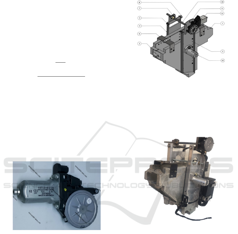
3.2 Mechanical Hand Prototype Design
Mechanical hand prototype design with electric
motor as prime mover. This mechanical hand is used
to attach the pull clamp isolator cap.
1. Fixed clamping press
plate
2. Movable clamping press
plate
3. Fixed hand
4. Hands move
5. Hinge
6. Electric motor moun
t
7. Threaded transmission
nut holder
8. Locking pen
9. Rings and snap rings
10. Threaded transmission
11. Electric motor
12. Clutch
Figure 4: Prototype Design of Mechanical Hand.
Figure 5: Prototype of Mechanical Hand.
3.3 Power, Rotation and Torque Test
Results
Direct Current Electric Motor Performance
Testing.The DC motor is coupled with a trapezoidal
thread shaft for opening and closing of the
mechanical hand. The DC motor that has been
determined is then tested for mechanical hand closing
movement. When installing the insulator cover, the
data taken are Power, Rotation of the drive shaft and
the time of installing the insulator cover.
Table 2 show that the measurement and
calculation data that show the relationship between
power, rotation and torque. The lowest rotation is
25.94 rpm with a torque of 11.83 Nm
The Design Prime Mover for Mechanical Hand Installer Pull Clamp Isolator
255
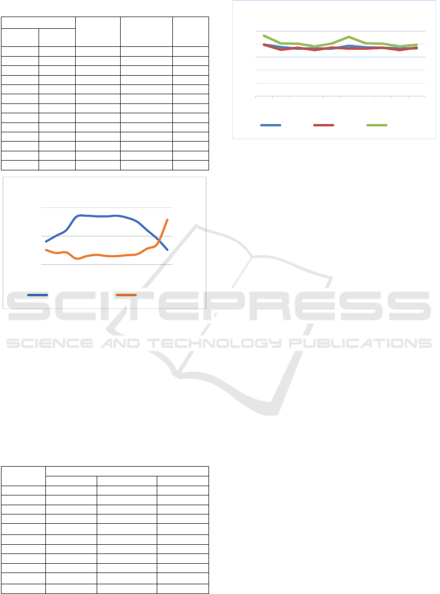
Table 2: Power, Rotation and Torque Test Result.
Avera
g
e
Power
(Watts)
Rotation
(Rpm)
Torque
(Nm)
Voltage
(Volt)
Current
(Amp)
5,30 1,36 16,28 40,53 3,84
9,63 1,34 16,12 50,65 3,04
9,77 1,70 20,40 60,54 3,22
9,63 1,48 17,80 84,00 2,02
9,83 1,67 20,08 85,84 2,23
9,60 1,90 22,80 84,73 2,57
9,77 1,67 20,08 84,62 2,27
9,53 1,68 20,20 85,84 2,25
9,63 1,79 21,52 82,45 2,49
9,47 1,79 21,52 75,42 2,73
9,10 2,22 26,64 60,22 4,23
9,50 2,15 25,84 45,30 5,45
6,60 2,68 32,12 25,94 11,83
Figure 6: Relatian between Rotation – Torque.
Figure 6 show that the relationship between
rotation and torque that occurs when installing the
insulator cover when tightening is when the rotation
goes down, it means the torque increases because the
power required is the same for tightening the insulator
clamps evenly.
While the duration of time in the process of
installing the insulator cover by mechanical hand is
shown in Table 3 below.
Table 3: Duration Time Installing Insulator Cover.
No
Duration Time (Second)
Line 1 Line 2 Line 3
1 39,71 39,61 46,59
2 37,73 35,7 40,57
3 36,55 37,29 40,41
4 36,76 35,51 38,23
5 36,59 37,38 40,51
6 38,71 36,61 45,58
7 37,57 36,58 40,67
8 37,14 37,29 40,41
9 36,75 35,51 38,23
10 36,79 37,36 39,55
Average 37,43 36,884 41,075
Figure 7: Duration Time Installing Insulator Cover.
The graph in Figure 7 shows that there is a time
difference in the process of installing the insulator
cover by mechanical hand for each line, but the time
difference is small, so it can be stated that the
installation time is almost the same.
4 CONCLUSIONS
Based on the results of testing and analysis can be
concluded as follows:
1. The working load on the mechanical arm is 8.23
Newtons. The main driving power from the
calculation results is 45.3585 watts. The DC motor
selected according to availability in the market is a
12 Volt, 48 Watt DC Motor.
2.The maximum torque required to drive the
mechanical hand is :5.45 Nm at 25.94 rpm.
3.The average time of installing the insulator cover is
38,463 seconds.
ACKNOWLEDGEMENTS
This research was funded by Lembaga Pengelola
Dana Pendidikan dan Direktorat Jenderal Pendidikan
Vokasi Kementerian Pendidikan, Kebudayaan, Riset,
dan Teknologi Year 2021. We thank Project
Management Office of Domestic Vocational Higher
Education Program Implementation of the Applied
Scientific Research in 2021 for his support to this
research..
REFERENCES
Ariadi, P., & Dinata, C. (2018). Students’ Mental Model
About Newton’ S Third Law in Indonesia: Analysis and
0,00
5,00
10,00
15,00
0,00
50,00
100,00
12345678910111213
Realtion Between Rotation - Torque
Rotation (Rpm) Torque (Nm)
0
10
20
30
40
50
12345678910
Duration Times
Line 1 Line 2 Line 3
iCAST-ES 2022 - International Conference on Applied Science and Technology on Engineering Science
256

Suggestion To Overcome It. Unnes Science Education
Journal (USEJ), 7(2), 146–155.
Caldwell, G. E., Robertson, D. G. E., & Whittlesey, S. N.
(2020). Forces and Their Measurement. In Research
Methods in Biomechanics. https://doi.org/10.5040/
9781492595809.ch-004
Iswanto, Ma’arif, A., Puriyanto, R. D., Raharja, N. M., &
Rahmadhia, S. N. (2020). Arduino Embedded Control
System of DC Motor Using Proportional Integral
Derivative. International Journal of Control and
Automation, 13(4), 658–667.
Math, K. (2013). Through-life management of electric
vehicles. International Through-Life Engineering
Services Conference, Procedia CIRP 11 ( 2013 ) 2nd.,
260 – 265.
Peerzada, P., Larika, W. H., & Mahar, A. A. (2021). DC
Motor Speed Control Through Arduino andL298N
Motor Driver Using PID Controller. International
Journal of Electrical Engineering & Emerging
Technology, 04(2), 21–24.
Purnata, H., Ramadan, S., Hidayat, M. A., & Maulana, I.
(2022). PID Control Schematic Design for Omni-
directional Wheel Mobile Robot Cilacap State of
Polytechnic. 12(2), 89–94.
Qader, M. R. (2017). Identifying the Optimal Controller
Strategy for DC Motors. IAES International Journal of
Robotics and Automation (IJRA), 6(4), 252.
https://doi.org/10.11591/ijra.v6i4.pp252-268
Ranjbar, A. H., Anahita Banei, A. K., & Fahimi, B. (2012).
Online estimation of state of charge in Li-Ion batteries
using implse respone concept. IEEE Transactions on
Smart Grid, 3(1).
Santika Wayan G, Urme, T., Eliz, S., A.Bahri, P., &
Anisuzzaman, M. (2020). An assessment of energy
policy impacts on achieving Sustainable Development
Goal 7 in Indonesia. International Energy Initiative.,
59(December), 33–48. Retrieved from https://www.
sciencedirect.com/science/article/pii/S0973082620302
921
Sarma, A. (2017). TECHNOLOGY. International Journal
of Engineering Sciences & Research Technology,
6(12), 57–79.
Sularso, & Suga, K. (2004). Dasar Perencanaan dan
Pemilihan Elemen Mesin. Jakarta. Jakarta: Pradnya
Paramita.
Xiaopeng., C., Weixiang, S., Tu, V. T., Zhenwei, C., &
Kapoor, A. (2012). An overview of lithium-ion
batteries for electric vehicles. Nternational Power &
Energy Conference, December 2012.
Zhaoguang, H., Xiandong, T., & Zhaoyuan, X. (2014). A
Review of china’s economic development and
electricity consumption, An Exploration into China’s
Economic Development and Electricity Demand by the
Year 2050. Cambridge: Elsevier Inc.
The Design Prime Mover for Mechanical Hand Installer Pull Clamp Isolator
257
