
Implementation of Low Cost Real Time GPS
Using the Haversine Method in Fishermen Electronic Navigation
Noviarianto Noviarianto
1
, Turahyo Turahyo
2
, P. Tony Kusumartono
1
and Amthori Anwar
1
1
Politeknik Maritim Negeri Indonesia, Indonesia
2
Sekolah Tinggi Teknologi Bontang, Indonesia
Keywords: GPS, Microcontroller, Ublox Neo-6M, Satellite, Fishing Boat.
Abstract: Fishermen who sail to catch fish in the sea generally already use electronic navigation in the form of the
Global Positioning System (GPS). This tool is utilized to assist in determining the position of the ship at sea.
Currently, GPS used by fishermen is still relatively expensive and quite difficult to operate. In this paper, GPS
is designed using the Haversine method and uses electronic components that are easily got on the market at a
price that is quite cheap and easy to use. In this system, the Ublox Neo-6M Module is used for communication
with the satellite to determine the position point. While the Atmega328 microcontroller on the Arduino Uno
board is used as the main controller of the system. To facilitate position monitoring, a LCD display with a
screen size of 20x4 is used. The display on the LCD screen is in the form of real time position in DMS,
distance in meters and directions to specify points, speed in knots and calendar. GPS design has been trials to
carry out the reference points with a distance of 10 meters to 300 meters. Built on the test results, it was found
that this GPS was able to show the position, direction of movement, ship speed and calendar quite accurately.
However, the accuracy of the GPS positioning point is also determined by the weather.
1 INTRODUCTION
Navigation equipment such as GPS plays a major
role in navigating the ocean (Sweet, 2003). It is easy
to determine the position of the archipelagic
boundaries by using GPS-assisted equipment
(Yulius & Salim, 2013). As one of the navigation
equipment, the use of GPS on modern ships is very
widespread, but the price of this navigation
equipment is quite expensive. Various brands and
types of navigation tools have been sold in the
market and are used extensively.
Research and design of GPS equipment to be
applied in several places such as the installation of
GPS modules to determine national boundaries
(Arfianto et al., 2018). However, in this study, the
modeling of regional boundaries still uses proximity
sensors mounted on microcontroller equipment. In
addition to point positions, directions to specify
points, speed of movement and calendars, are
discussed in this paper. In this paper, reference
points are also determined that serve as the basis for
calculations in the microcontroller program.
Monitoring of position points can be seen using the
20x4 LCD screen which contains quite a lot of the
required characters.
2 THEORETICAL BASIS
GPS is an electronic equipment used to determine
the position of a place (E. Ceruzzi, 2018). GPS
receivers work by figuring out how far from a
number of satellites that are located in Earth orbit.
This GPS is planned to find out which gps satellites
are at a certain time. Satellites transmit information
in the form of digital data wrapped in radio signals
about the current position and time. This signal
identifies the satellite and tells the receiver where it
locates.
The radio receiver's electronic equipment
calculates how far each satellite is by figuring out
how long it takes for the signal to be provided. Once
you have that information about the GPS can
pinpoint your exact location on Earth. In general, no
less than 3 satellites are accustomed. This process is
commonly known as Trilateration (Engineers, n.d.)
as showed in Figure1.
284
Noviarianto, N., Turahyo, T., Kusumartono, P. and Anwar, A.
Implementation of Low Cost Real Time GPS Using the Haversine Method in Fishermen Electronic Navigation.
DOI: 10.5220/0011760500003575
In Proceedings of the 5th International Conference on Applied Science and Technology on Engineering Science (iCAST-ES 2022), pages 284-289
ISBN: 978-989-758-619-4; ISSN: 2975-8246
Copyright © 2023 by SCITEPRESS – Science and Technology Publications, Lda. Under CC license (CC BY-NC-ND 4.0)

Figure 1: Trilateration GPS.
2.1 Ublox Neo-6M Module
In this paper, the satellite receiver module used is the
Ublox Neo-6M module. This module is useful in
modeling electronic devices to determine the position
(Yulius &Salim, 2013), as well as position tracking
(Budiman et al., 2020). This gps module has the
advantage of being able to prove the fixed position in
cold start conditions for about 27 seconds with a 50
channel receiver type. The sensitivity of the module
in tracking and navigation conditions is -161 dBm.
While the level of accuracy of the GPS horizontal
position of this module is 2.5 m. communication
systems interfaces and protocols that can be used are
UART, USB and serial peripheral interface (SPI).
The operating voltage of this module is a maximum
of 3.6 V and a current of 100 mA (U-blox, 2017). The
accuracy level of the Ublox Neo-6M module is quite
mild compared to the Neo-M8N module (Firdaus &
Ismail, 2020). The Ublox Neo-6M satellite signals
receiver module and pin positions are shown in
Figure 2. 3.
The pins contained in the Ublox Neo-6M module
are 4 consisting of: (1) GND (ground) connected to
Arduino ground, (2) TX (transmitter) is used for serial
communication, (1) RX (receiver) is used for serial
communication, (4) VCC is connected to the power
supply or can be directly connected to 5V on the
Arduino pin. The communication system between the
Ublox Neo-6M Module and the microcontroller uses
UART. This module supports baud rate 4800bps –
230400bps with the default baud rate of 9600. On the
module there is also a LED that will flash every
Figure 2: Ublox Neo-6M Module.
1 second if the satellite is fixed. In addition there is a
battery that can be charged, and a 3.3V voltage
regulators. The module is further equipped with a
serial EEPROM with a memory capacity of 4KB
which is connected to the NEO-6M chip using I2C
communication. In this module there is likewise a
satellite receiving antenna with a sensitivity of -161
dBm. This antenna is attached to a U.FL cable and
connector. Serial data generated from the Ublox Neo-
6M module is in the form of NMEA sentences.
NMEA is submitted to National Marine Electronics
Association which is the standard format on all GPS
receivers. The NMEA standard is in the form of rows
of data called sentences. Each sentence is delimited
by a comma to facilitate the parsing of data on a
computer or microcontroller. This NMEA sentence
will be transmitted in a certain interval called the
update rate. Information updated by default on the
Neo-6M module is one per second or 1Hz frequency,
but can be set to 5 data per second or 5Hz frequency.
The most common is $GPRMC (Global
Positioning Recommended Minimum Coordinates)
which provides time, date, latitude, longitude and
estimated speed. $GPGGA This sentence presents an
essential data fix that provides 3D location and data
accuracy.
2.2 Microcontroller
The microcontroller device is used as a controller and
signal processor from the GPS receiver module. This
microcontroller is Atmega328 which is built-in an
Arduino Uno development board as showed in Figure
Implementation of Low Cost Real Time GPS Using the Haversine Method in Fishermen Electronic Navigation
285
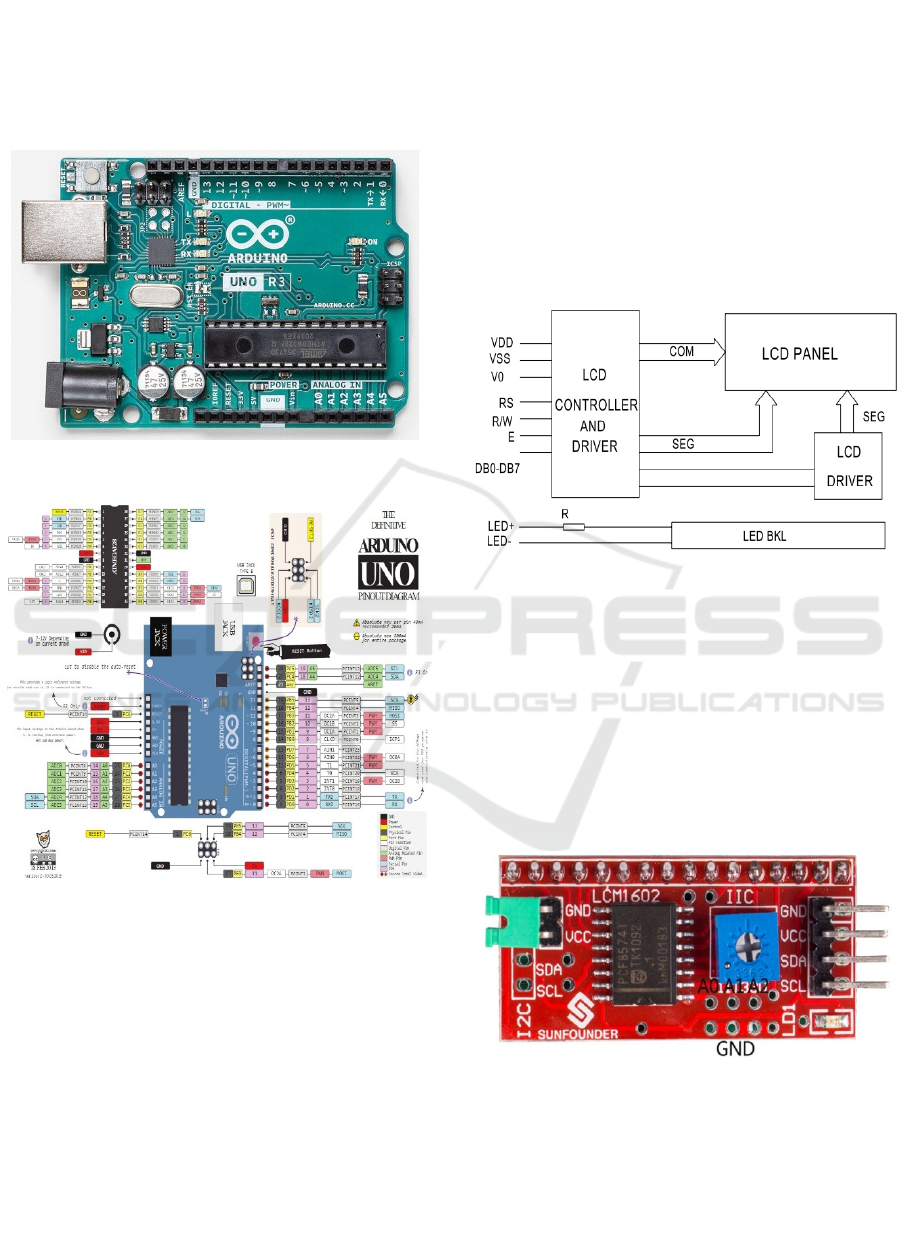
3. The operating voltage of this board is 5V. It has 32
KB of flash memory, and 2KB as a boot loader. The
clock speed is 16 Mhz. This microcontroller is
equipped with digital I/O, Analog IN, and PWM
output pins (Arduino, 2021). In detail pins found on
the Arduino Uno can be observed in Figure 4.
Figure 3: Arduino Uno Board.
Figure 4: Pinout Arduino Uno.
Arduino Uno will process serial data from Ublox
Neo-6M. The data will be processed and displayed on
the LCD screen. Positioning modeling (Arfianto et
al., 2018) is not equipped with a screen that shows the
position directly. In this paper, because it serves as a
navigational aid, a position indicator in the form of a
screen is necessary. The addition of a 20x4 character
LCD screen is supposed to be sufficient to display the
required data.
2.3 LCD
The LCD module in this paper is a 20x4 LCD type.
This LCD has 20 character columns and 4 rows. Each
character makes up to 5x8 dots. Built-in controller
with S6A0069 series or equivalent. Supply voltage
5V and fitted with LED backlight. This LCD module
has 16 pins that are utilized to display characters on
the screen. LCD is likewise composed of several
blocks consisting of controller, driver, led backlight,
and LCD panel. The block diagram can be viewed in
Ga Figure 5. (Ocular, 2003). Turning on a 20x4 LCD
requires a lot of cables to connect. To reduce the need
for cables and pins on the microcontroller, in this
paper the LCD is connected to the I2C serial interface
module. The I2C serial interface module used has a
PCF8574T chip (Semiconductors, 2002).
Figure 5: LCD Block Diagram.
The use of the I2C serial interface on the 2004
LCD only requires 4 pins to carry on the LCD. The
four pins are: (1) GND which is connected to the
microcontroller ground, (2) VCC is connected to a 5V
voltage source, (3) SDA is connected to Analog pin
4, (4) SCL is connected to Analog pin 5. The shape of
the I2C board can be observed in Figure 7. On the
PCF8574T chip, the address for I2C is of the format:
0 1 0 0 A2 A1 A0. The factory default address is 0x27.
While the address ranges is between 0x20 - 0x27.
Figure 6: I2C Serial LCD Board.
2.4 DMS Conversion
Decimal Degree (DD) is a notation for expressing
geographic coordinates of latitude and longitude as a
decimal fraction of a degree. Decimal degrees are
used in various geographic information systems
iCAST-ES 2022 - International Conference on Applied Science and Technology on Engineering Science
286
(GIS), web mapping applications such as Open Street
Map, and GPS devices. Decimal degrees are an
alternative to using sexagesimal degrees (degrees,
minutes, and seconds - DMS notation). As with
latitude and longitude, values are limited by ±90 and
±180, respectively (Wikipedia, 2022). Converting
DMS coordinates to decimal degrees is a work of
converting the minute and second components to
decimal degrees. Converting minutes and seconds to
degrees are equal to turning minutes and seconds into
hours. Where 1 minute = 1/60 hour and 1 second =
1/3600 hour.
Positive latitudes are north of the equator. Negative
latitudes are south of the equator. Positive longitude
is east of the Prime Meridian while negative longitude
is west of the Prime Meridian. Latitude and longitude
are usually expressed in order of latitude before
longitude. Nautical Miles is 60 miles = 1° flat = 1°
long at the equator. If 1 degree latitude is 111.3 km at
the equator, then the change in a fraction of a minute
is: (1) 1 degree = 60 minutes, (2) 1 minute = 1
degree/60 = 111.32km / 60 = 1,855km, (3) 1 minute
= 1855m, (4) 0.1min = 185.5m, (5) 0.01min =
18.55m, (6) 0.001min = 1.855m, (7) 0.0001min =
0.1855m = 185.5mm, (8) 0.00001min = 0.0185m =
18.55mm = 1.855cm. The more decimal places
behind the comma, the higher the GPS accuracy will
be.
Conversion of DD to DMS can be done as in the
example: on GPS the geographical position is -
7.020222 110.401566 then if converted to DMS is: -
7.020222= 7(0.02022*60) = 1.21332=
1(0.21332*6)= 12.7992 S is written 7° 1 12.7992″ S
110.401566 = 110, 0.401566*60 = 24.09396 =24
0.09396*60 = 5.6376 E is written 110° 24′ 5.6376″ E.
So the position in DMS is 7° 1′ 12.7992″ South
Latitude 110° 24′ 5.6376″ East. In this paper, the
position point display is displayed on the LCD screen
in DMS format. It is intended to make it easier to read
the position according to the paper map. Some
characters such as degrees, minutes, and seconds are
not part of the library. In this study, a special character
was in addition to display it.
2.5 Haversine Method
In this paper, the Haversine method is utilized to
calculate calculate the distance between coordinates
in a geographic projection system (decimal
degrees/DD). This method calculates the shortest
distance between two points on a curved surface by
utilizing the latitude (Y-value) and longitude (X-
value) values at that point. This calculation is of great
importance to use in navigation (Yulianto,
Ramadiani, & Kridalaksana, 2018). Haversine own
formula is as following:
𝑎=𝑠𝑖𝑛
∆𝜑
2
+𝑐𝑜𝑠𝜑
.𝑐𝑜𝑠𝜑
.𝑠𝑖𝑛
∆
2
(1)
𝑐 = 2.𝑎𝑡𝑎𝑛
√
𝑎,
√
(1−𝑎)
(2)
d = R.c
(3)
The following information: (1) 𝜑 = latitude, (2) λ =
longitude, (3) R = earth radius/ mean radius =
6.371km. In order for trigonometric functions to work
properly, the angle values must be in radians.
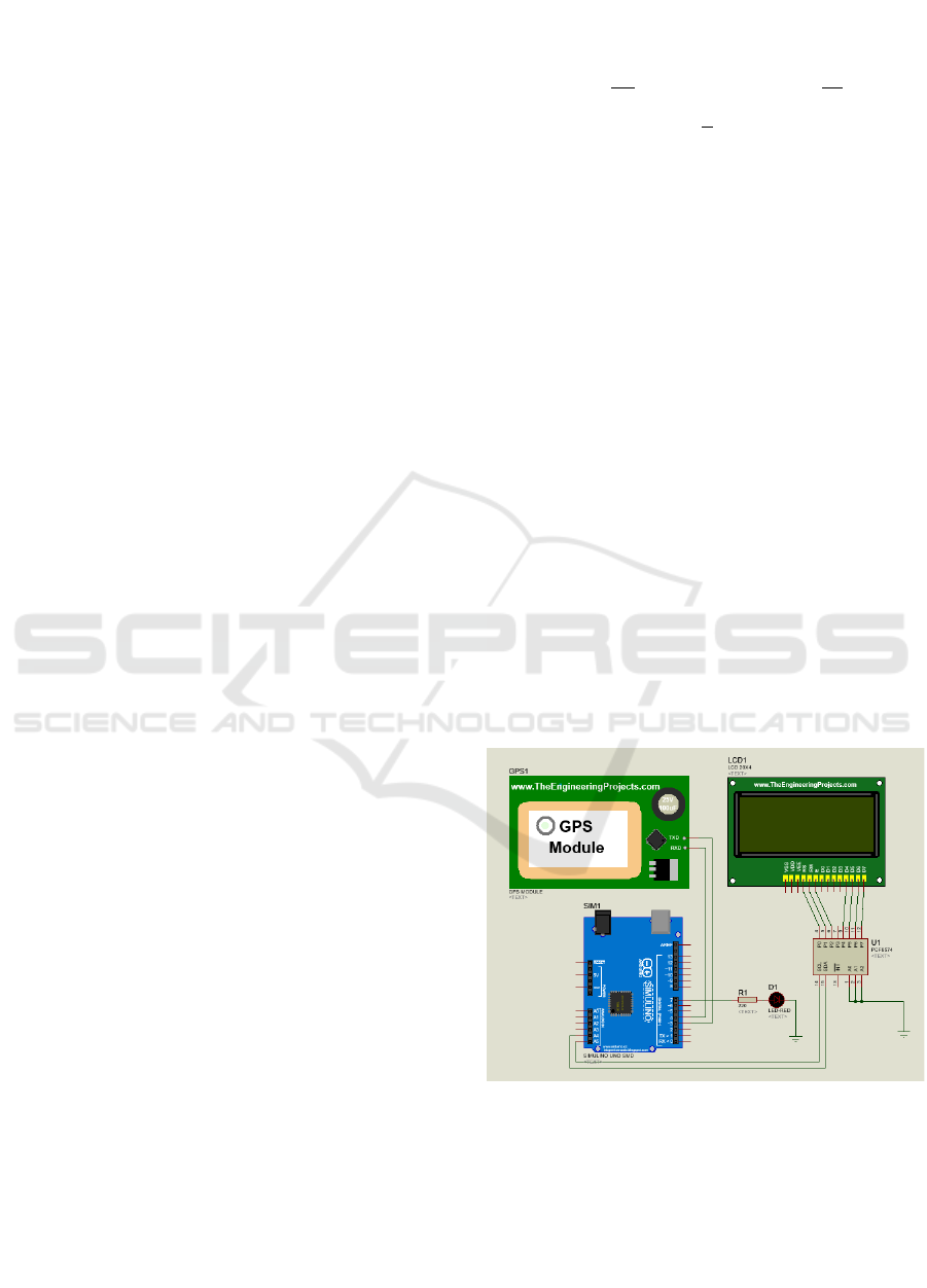
3 PROPOSED SYSTEM
In this paper, a schematic of the low cost GPS circuit
design is shown as showed in Figure 7. In the figure,
it consists of a Ublox Neo-6M GPS module
connected to a microcontroller. The Tx data pin of the
Ublox Neo-6M module is attached to pin 3 and the
Rx data pin is connected to pin 4 of the Arduino Uno.
The 20x4 LCD is utilized to display the current
position and is connected to the PCF8574 I2C
module. On the SCL and SDA pins of the I2C
module, they are connected to pins on A5 and pins A4
of Arduino Uno, respectively. The indicator in the
form of a LED that will flash when approaching the
reference point at a distance of less than 300m is
connected to pin 7.
Figure 7: GPS circuit schematic.
In addition, to simplify the system design, a system
architecture is made. This GPS architecture consists
of a GPS module as an input signal to the
microcontroller, a voltage source from 2 of 18650
batteries, and at the output of a LED lamp and a 20x4
character LCD module as showed in Figure 8.
Implementation of Low Cost Real Time GPS Using the Haversine Method in Fishermen Electronic Navigation
287
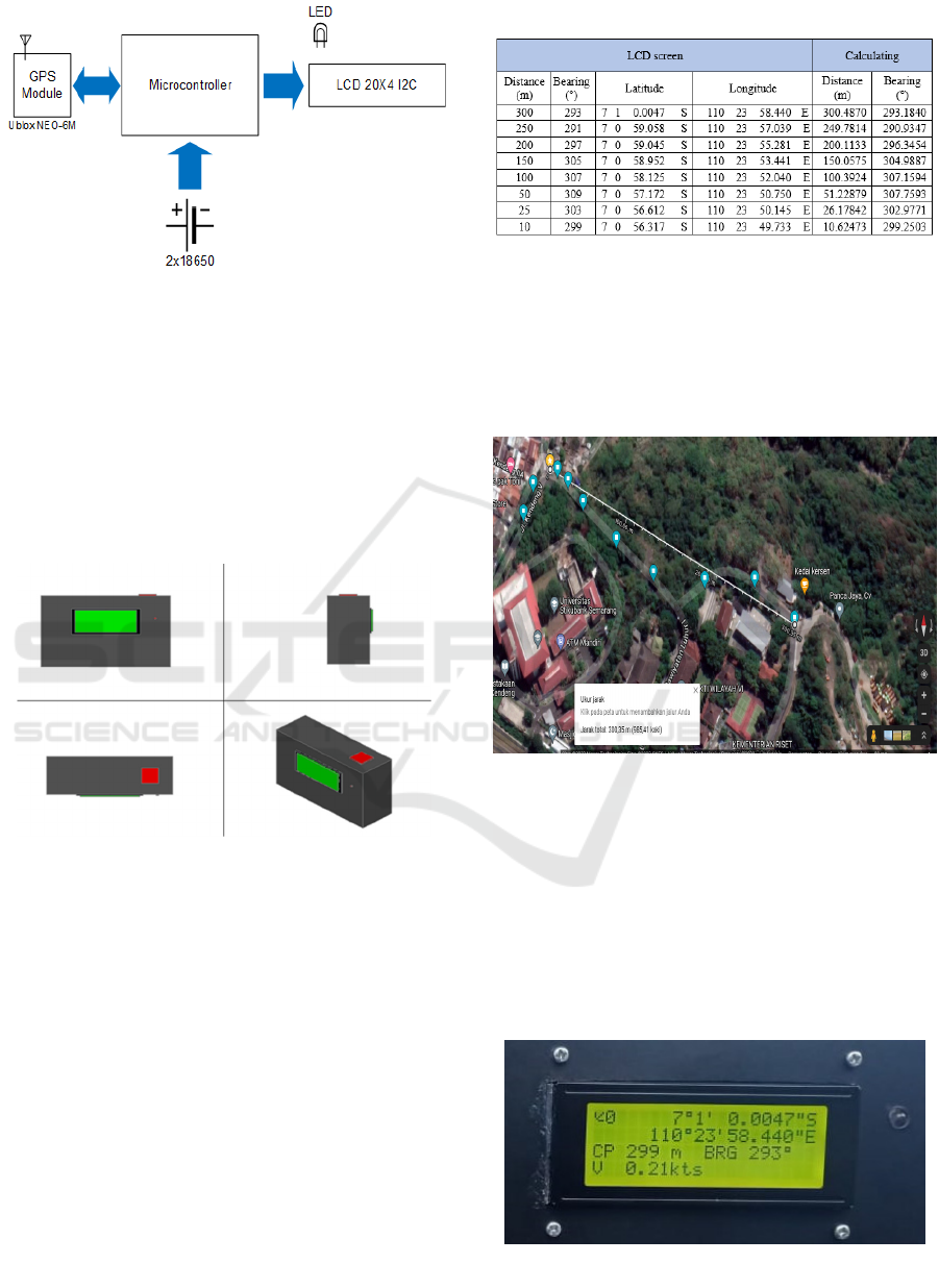
Figure 8: GPS architecture.
In this paper, all existing electronic components are
contained in the X6 black plastic box. The design of
the GPS box that makes as in Figure 9. On the front
are placed a 20x4 LCD and LED indicators. The top
is placed on the GPS signal receiving antenna. The
voltage source to run all the equipment is obtained
from 2 Lithium ions 18650 batteries. Both batteries
are installed in series and each has a voltage of 3.7V,
so the available voltage is around 7.4V.
Figure 9: GPS box design model.
4 RESULT AND ANALYSIS
Data retrieval is achieved by bringing the GPS
equipment that has been made close to the reference
points that have been determined. After that, the
coordinates are shown at that distance. The data
generated in the position towards the reference points
as indicated in Table 1. In the table the results of the
display on the LCD screen are recorded. The resulting
data are latitude and longitude positions in DMS
format. On the screen will show the distance and
bearing. In the column on the right are included in the
results of calculations using the Haversine formula.
The indication on the LCD screen and the calculation
results is not too far apart.
Table 1: Data to reference points.
To make it easier to analyze the test results. It is
illustrated using a Google Map. The measurement
position point is indicated by a blue marking on the
Google map. Figure 10 indicates the position of the
marking points to the reference points. Measurements
are taken by walking along the road and getting closer
to the points as a reference.
Figure 10: Plotting to reference points on Google Map.
In addition, the 20x4 LCD screen display can be seen
as showed in Figure 11. The first row on the left is the
number of satellites. The first and second rows
indicate the latitude and longitude positions. CP or
closes point shows the distance to the nearest point.
BRG is the bearing to the nearest point in degrees.
Data display on the LCD screen. Calculation results,
and plotting on Google map shows the appropriate
distance and bearing.
Figure 11: GPS LCD screen display.
iCAST-ES 2022 - International Conference on Applied Science and Technology on Engineering Science
288

5 CONCLUSIONS
Testing and data retrieval using the GPS design has
been executed. The GPS design created can display
the position in real time and is presented on a 20x4
LCD screen. The displayed position is in DMS
format, making it more convenient for fishermen to
read the position. In addition, in this paper, a point is
determined as a reference point and the results of the
data can show the distance to the reference points
with results that is not too far apart. In this paper, the
distance and bearing measurements are not more than
300m and not less than 10m.
REFERENCES
Arduino, C. (2021). Arduino Nano.
Arfianto, A. Z. ;, Gunantara, N., Rahmat, M. B., Setiyoko,
A. S., Handoko, C. R., Hasin, M. K., … Aminudin, A.
(2018). Perangkat Informasi Dini Batas Wilayah
Perairan Indonesia Untuk Nelayan Tradisional Berbasis
Arduino Dan Modul Gps Neo-6M. Joutica, 3(2), 163–
167.
Budiman, M. A., Harefa, A. Z., Shaka, D. V., Studi, P.,
Informatika, T., Informasi, F. T., … Print, F. (2020).
Perancangan sistem pelacak gps dan pengendali
kendaraan jarak jauh berbasis arduino, 978–979.
E. Ceruzzi, P. (2018). GPS. Massachusetts Institute of
Technology.
Engineers, L. M. (n.d.). Interface ublox NEO-6M GPS
Module with Arduino. Retrieved from
Firdaus, F., & Ismail, I. (2020). Komparasi Akurasi Global
Posistion System (GPS) Receiver U-blox Neo-6M dan
U-blox Neo-M8N pada Navigasi Quadcopter.
Elektron : Jurnal Ilmiah, 12(1), 12–15.
https://doi.org/10.30630/eji.12.1.137
Ocular, X. (2003). GDM2004D. Data Sheet.
Pangaribuan, P., & Rusdinar, A. (2016). Design and
Implementation of Prototypes Monitoring System
Position Boat Fishing in Sea Water using GPS System
Based Arduino with Kalman Filter Method. e-
Proceeding of Engineering (Vol. 3, pp. 4097–4102).
Semiconductors, P. (2002). Data Sheet PCF8574. Retrieved
from
Sweet, R. J. (2003). GPS for Mariners. The McGraw_Hill
Companies.
U-blox. (2017). NEO-6 u-blox 6 GPS Modules. Www.U-
Blox.Com
Wikipedia. (2022). Decimal degrees. Retrieved from
https://en.wikipedia.org/wiki/Decimal_degrees
Yulianto, Y., Ramadiani, R., & Kridalaksana, A. H. (2018).
Penerapan Formula Haversine Pada Sistem Informasi
Geografis Pencarian Jarak Terdekat Lokasi Lapangan
Futsal. Informatika Mulawarman : Jurnal Ilmiah Ilmu
Komputer, 13(1),14. https://doi.org/10.30872/jim.v13
i1.1027
Yulius, & Salim, H. L. (2013). Aplikasi GPS dalam
Penentuan Posisi Pulau di Tengah Laut Berdasarkan
Metode Toponimi (Studi Kasus Pulau Morotai dan
Sekitarnya). In Seminar Nasional Pemberdayaan
Informasi Geospatial untuk Optimalisasi otonomi
daerah 2013 (pp. 104–108).
Implementation of Low Cost Real Time GPS Using the Haversine Method in Fishermen Electronic Navigation
289
