
Analysis on Distance Relay Setting and Coordination at 150 KV
High Voltage Transmission Line Kentungan Godean Bantul Semanu
Yusnan Badruzzaman and Afrizal Fawaid Fasihfauzi Ahmad
D3 Electrical Engineering Study Program, Electrical Engineering Department, Semarang State Polytechnic,
Jl. Prof. H. Soedarto, SH Tembalang Kota Semarang 50275, Indonesia
Keyword: Distance Relay, Setting, Impedance, Coordination.
Abstract: High voltage power lines of 150 kV are one part of the electric power transmission system that has a fairly
large potential for disturbance. The relevancy of a protection system on the High Voltage Power Lines of
150 kV. Distance relays are commonly used as the main protection of device on high-voltage power lines of
150 kV. Determining the distance relay setting requires calculating the zona impedance value and
coordination, as well as simulating short circuit faults on each line to determine each distance relay
operation. The method used is a comparative method that compares the calculation results with the settings
from PLN and is assisted by the DigSILENT software to make it easier to analyze. The results of
calculations and simulations are compared with setting from PLN. From this comparison, it is obtained the
settings form PLN got zona-3 overlapping at Substation Kentungan in the direction of Godean with zona-3
Substation Godean in the direction of Substation Bantul, the selection of zona impedance values is not
optimal in zona-2 Substation Godean in the direction of Bantul, zona-3 Substation Semanu in the direction
of Bantul and zona -3 Substation Bantul Arah GI Godean, and zona-1 Substation Kentungan in the direction
of Godean does not reach 80% of the main line.
1 INTRODUCTION
An electric power system consists of three main
parts, namely power generation, transmission system
and distribution system. The transmission system is
an important part in the distribution of electrical
energy from power plants to load centers or
consumers. The long distance between the power
plant and the load center makes the transmission
system have the potential for large disturbances.
Disturbances that occur can be caused by system
errors, as well as non-system disturbances such as
natural disturbances such as lightning strikes, fallen
trees, and storms. The fault causes a short circuit of
three phases, three phases to ground, two phases,
two phases to ground and one phase to ground.
The protection system is mandatory in the
electric power system in order to secure equipment
and separate disturbed areas. A very vital component
in the protection system is the relay. The protection
relay is one of the main components in the electric
power system that can have a major impact on the
electric power system. The protection relay will
identify a disturbance in the system by measuring
the electrical quantity that is read by a measuring
instrument which is always read in normal or fault
conditions. The relay will instruct the PMT to trip to
cut off electricity if it detects a fault condition. One
of the protection relays that are often used is the
distance relay which protects the transmission from
short circuit interference.
Distance relays are usually used as the main
safety of overhead lines on transmission networks
both at 150 kV and 500 kV voltages. The way the
distance relay works is to use the current and voltage
measurements obtained from current transformers
and voltage transformers to determine the
impedance value of a transmission line. The distance
relay will work if the impedance value read is less
than the relay setting value. If the read impedance
value exceeds the setting value, the distance relay
will not work.
Setting the distance relay greatly affects the
reliability of the relay itself, with the right setting
value, the distance relay can work optimally and
quickly in separating disturbed parts from other parts
that are still healthy and at the same time securing
healthy parts from damage or greater losses. .
Badruzzaman, Y. and Ahmad, A.
Analysis on Distance Relay Setting and Coordination at 150 KV High Voltage Transmission Line Kentungan Godean Bantul Semanu.
DOI: 10.5220/0011764400003575
In Proceedings of the 5th International Conference on Applied Science and Technology on Engineering Science (iCAST-ES 2022), pages 307-312
ISBN: 978-989-758-619-4; ISSN: 2975-8246
Copyright © 2023 by SCITEPRESS – Science and Technology Publications, Lda. Under CC license (CC BY-NC-ND 4.0)
307
Therefore, the value of the distance relay setting
must be considered properly so that the relay can
work optimally
2 RESEARCH METHODS
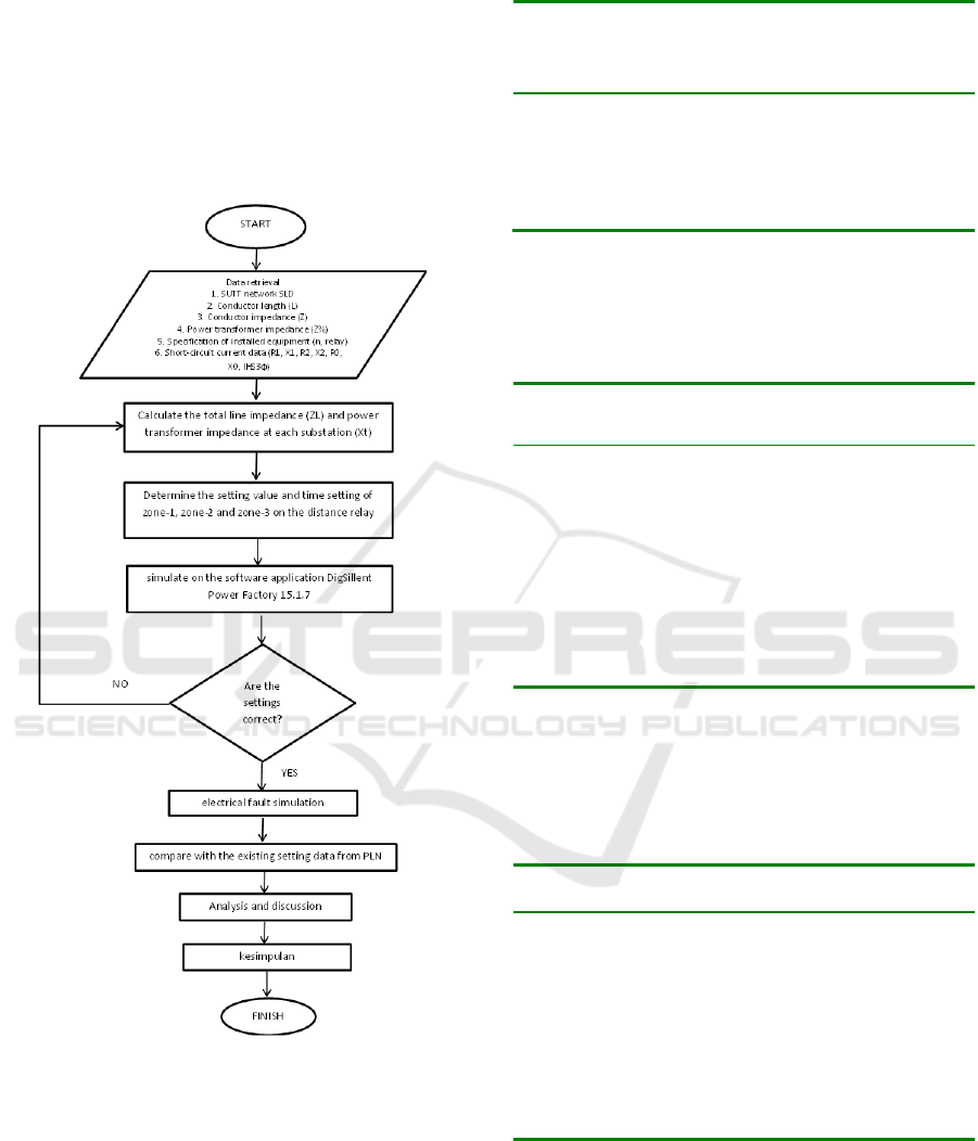
2.1 Research Step
Figure 1: Diagram Alir Penelitian.
2.2 Research Data
There are 6 distance relays to protect the studied
channel. The relays include GI Kentungan arag
Godean, GI Godean to Bantul, GI Godean to
Kentungan, GI Bantul to Godean, GI Bantul to
Semanu, and GI Semanu to Bantul. To be able to
calculate the setting, the following data is needed for
the conductor.
Table 1: Conductor Data.
Line Length
(km)
Positive
Sequence
Impedance
(Ω/km)
Zero
Sequence
Impedance
(Ω/km)
Kentungan -
Godean
9,1771 0,137 + j
0,3966
0,287+j
1,19
Godean -
Bantul
13,211 0,137 + j
0,3966
0,287+j
1,19
Bantul -
Semanu
39,043 0,137 + j
0,3966
0,287+j
1,19
To change the value on the primary side of the
conductor into the value of the relay side, the ratio of
the measurement tool is needed as follows.
Table 2: Ratio of Measurement Tools.
Substation Protection
Direction
Ratio
Measurement Transformer
Kentungan Godean CT 800/1 A
CVT 150.000/100V
Godean Kentungan CT 600/1 A
CVT 150.000/100V
Bantul CT 600/1 A
CVT 150.000/100V
Bantul Godean CT 1000/1 A
CVT 150.000/100V
Semanu CT 500/1 A
CVT 150.000/100V
Semanu Bantul CT 500/1 A
CVT 150.000/100V
In setting the distance relay also consider the
impedance of the power transformer in the front
substation. The following is the power transformer
impedance data at each substation:
Table 3: Power Transformer Impedance Data.
Substation Power
Transformer
Impedance (pu)
Kentungan Trafo 2 11,93 %
Trafo 3 12,06 %
Trafo 4 12,13 %
Godean Trafo 1 12,25 %
Trafo 2 12,11 %
Bantul Trafo 1 11,92 %
Trafo 2 11,51 %
Trafo 3 11,86 %
Semanu Trafo 1 12,18 %
Trafo 2 11,31 %
The distance relay works based on the read
impedance. If the read impedance is less than the
setting impedance, the relay will work, but if the
read impedance is more than the setting impedance,
the relay will not work. To be able to determine the
setting on the distance relay, the following equation
is used.
iCAST-ES 2022 - International Conference on Applied Science and Technology on Engineering Science
308

1. Total Impedance of Conductor
In determining the setting required the total line
impedance obtained from the equation:
ZL = Z × L (1)
Where:
ZL = Total Conductor Impedance (Ω)
Z = Impedance of conductor (Ω/km)
L = conductor length (km)
1. Power Transformer Impedance
Setting the distance relay must pay attention to
the impedance of the power transformer at the
front substation. The data taken from PLN is still
in the form of pu, so it must be converted into
ohms with the equation:
Xt =
% ×
(2)
Where:
Xt = Transformer impedance (Ω)
Zt = transformer impedance (pu)
V = nominal voltage (kV)
S = Transformer capacity (MVA)
1. Ratio of CT and CVT
To change the impedance that is read on the
primary side, it is necessary to transform the
impedance to the relay side using the existing CT
and CVT ratios with the equation:
n =
(3)
Where:
n = Ratio of measuring tool
kCT = CT ratio
kCVT = CVT ratio
1. Setting Zone-1
To determine the impedance setting zone-1 can
use the following equation:
Zone-1 = n × 0.8 × ZL1 (4)
Where:
n = Ratio of measuring tool
ZL1 = Total impedance of main conductor
Zone-1 working time also needs to be set with a
working time of 0 seconds (instant)
2. Setting Zone-2
To determine the impedance setting for zone-2,
you can use the following equation:
Zona-2
min
= n × 1,2 × ZL1 (5)
Zona-2
mak1
= n × 0,8 (ZL1+0,8.ZL2) (6)
Zona-2
mak2
= n × (ZL1+0,5Xt) (7)
Where:
n = Ratio of measuring tool
ZL1 = Total impedance of main conductor
ZL2 = Total impedance of front GI shortest
conductor
Xt = Power transformer impedance
From equations (5) and (6) the largest value is
chosen but it should not exceed the impedance
value (7). Zone-2 working time also needs to be
set with a working time of 0.3-0.8 seconds.
1. Setting Zone-3
To determine the impedance setting for zone-3,
you can use the following equation:
Zona-3
min
= n × 1,2 (ZL1+ZL3) (8)
Zona-3
mak
= n × 0,8 (ZL1+0,5.Xt) (9)
Where:
n = Ratio of measuring tool
ZL1 = Total impedance of main conductor
ZL3 = Total impedance of front GI longest
conductor
Xt = Power transformer impedance
From equations (5) and (6) the largest value is
chosen. Zone-3 working time also needs to be set
with a working time of 0.8-1.6 seconds.
3 RESULTS AND DISCUSSION
3.1 Distance Relay Setting
From the results of calculations with the equations in
chapter 2, the results of the settings are as follows:
Table 4: Calculation Results of Distance Relay Settings.
Substation Protection
Direction
Zone Impedance
(Ω)
Working
Time
Kentungan Godean Zona-1 1,643 0 s
Zona-2 3,535 0,4 s
Zona-3 11,256 1,6 s
Godean Kentungan Zona-1 1,232 0 s
Zona-2 2,753 0,4 s
Bantul Zona-1 1,774 0 s
Zona-2 3,405 0,4 s
Zona-3 10,524 1,2 s
Analysis on Distance Relay Setting and Coordination at 150 KV High Voltage Transmission Line Kentungan Godean Bantul Semanu
309
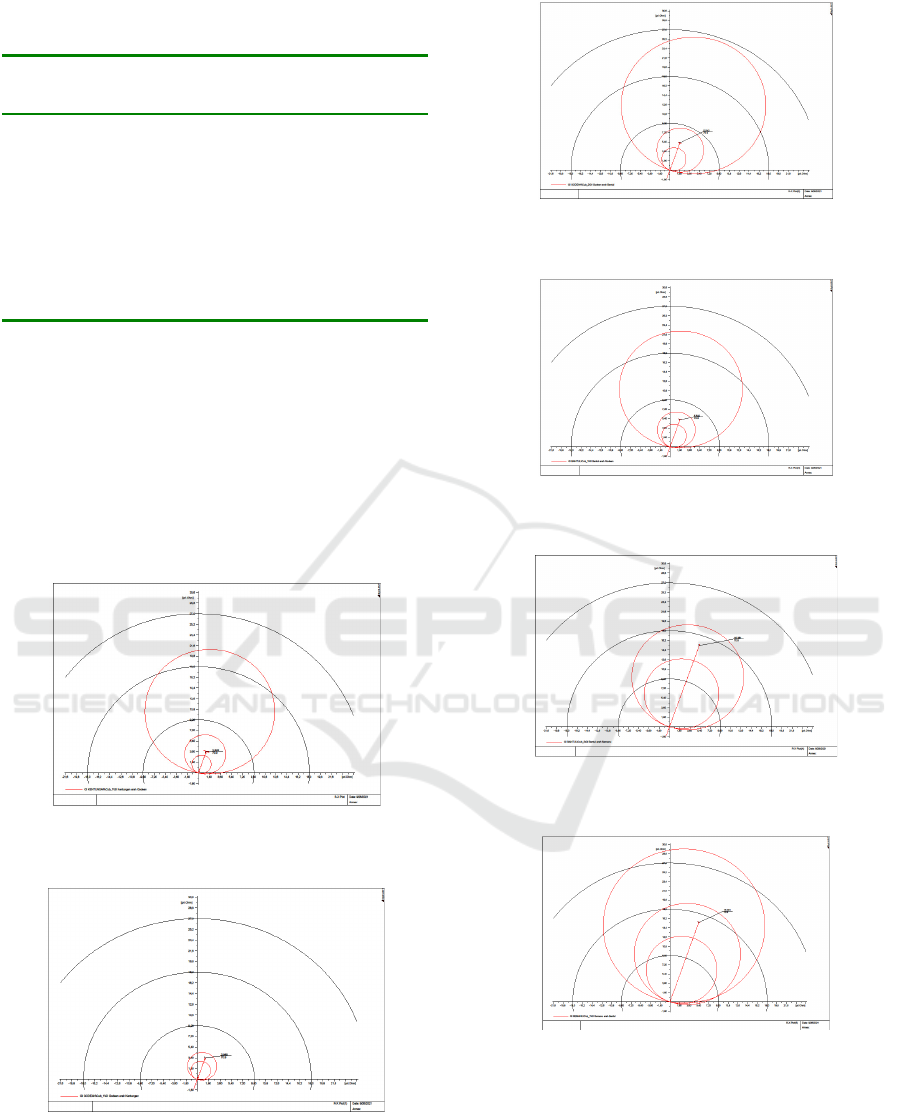
Table 4: Calculation Results of Distance Relay Settings
(cont.).
Substation Protection
Direction
Zone Impedance
(Ω)
Working
Time
Bantul Godean Zona-1 2,956 0 s
Zona-2 4,599 0,4 s
Zona-3 14,939 1,2 s
Semanu Zona-1 4,369 0 s
Zona-2 6,553 0,4 s
Semanu Bantul Zona-1 4,369 0 s
Zona-2 6,553 0,4 s
Zona-3 9.987 1,6 s
From the table, the impedance setting and working
time of zone-1, zone-2, and zone-3 are obtained for
each relay for each substation.
3.2 R-X Plot Diagram
The setting results that have been obtained are
entered in the DigSILENT software simulation
program and an R-X Plot Diagram is obtained as
shown in the following figure:
Figure 2: R-X Plot Diagram of GI Distance Relay
Kentungan direction Godean.
Figure 3: R-X Plot Diagram of GI Godean Distance Relay
in Kentungan direction.
Figure 4: R-X Plot Diagram of the Godean GI Distance
Relay in the direction of Bantul.
Figure 5: R-X Plot Diagram of the Distance Relay of GI
Bantul in Godean direction.
Figure 6: R-X Plot Diagram of the Distance Relay of GI
Bantul in Semanu direction.
Figure 7: R-X Plot Diagram of the Semanu GI Distance
Relay in Bantul.
From Figure 3 to Figure 8, the protection area of
each zone is shown in a circle.
iCAST-ES 2022 - International Conference on Applied Science and Technology on Engineering Science
310
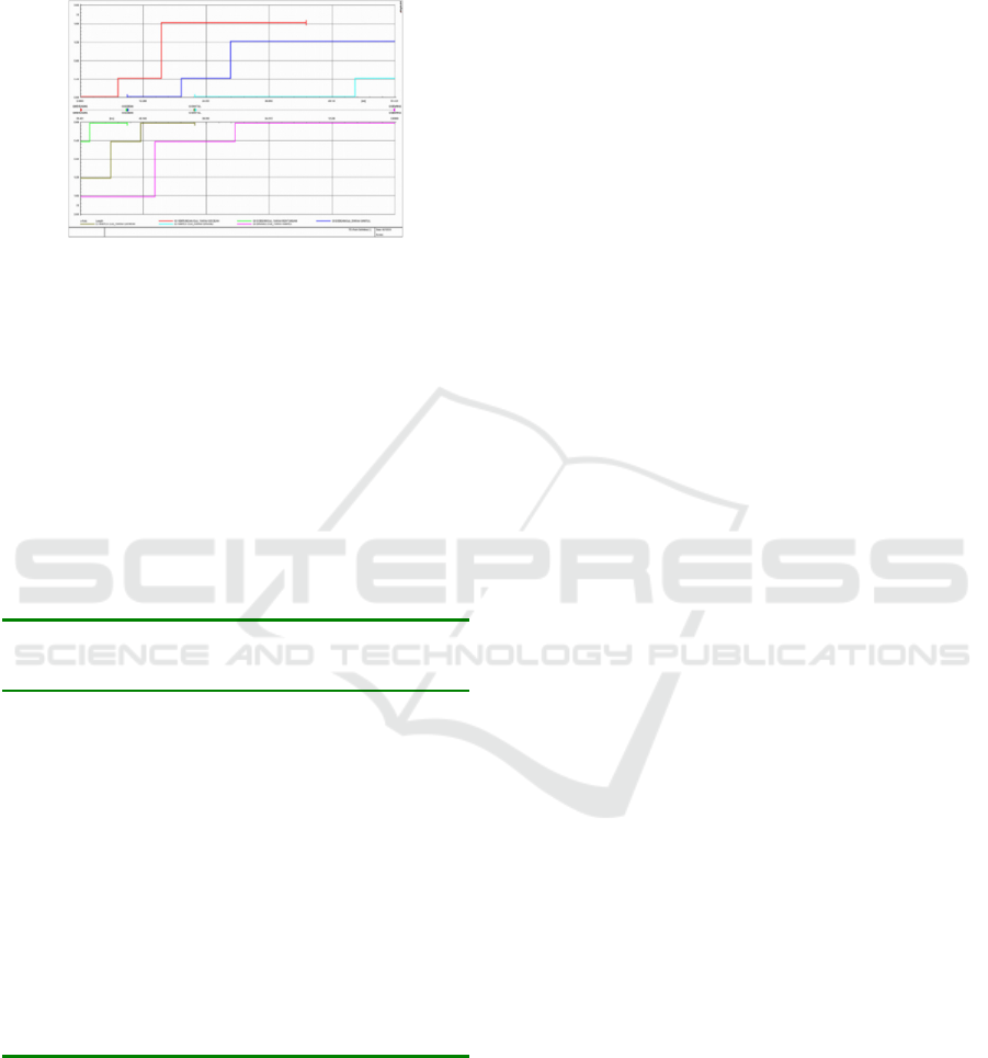
3.3 Time Distance Diagram
The following is the Time-Distance diagram of the
simulation results using the DigSILENT software.
Figure 8: Time-Distance Diagram Setting Calculation
Results.
From Figure 8, it can be seen that the distance relay
coordination between substations is correct.
3.4 Comparison with PLN's Existing
Settings
Setting the calculation results in theory compared to
the existing PLN settings can be seen in the
following table:
Table 5: Comparison of Calculation Settings with PLN.
Substations
Direction
of
Protection
Zone
Calculation
Setting (Ω)
PLN
Setting
(
Ω
)
Kentungan Godean Zona-1 1,643 1,55
Zona-2 3,535 3,34
Zona-3 11,256 11,23
Godean Kentungan Zona-1 1,232 1,232
Zona-2 2,753 14,151
Bantul Zona-1 1,774 1,774
Zona-2 3,405 4,169
Zona-3 10,524 10,637
Bantul Godean Zona-1 2,956 3,138
Zona-2 4,599 4,841
Zona-3 14,939 7,7
Semanu Zona-1 4,369 4,567
Zona-2 6,553 8,194
Semanu Bantul Zona-1 4,369 4,369
Zona-2 6,553 6,553
Zona-3 9.987 14,082
From the comparison above, it can be seen that there
are existing PLN settings that are less than optimal
and there is still overlapping in the distance relay of
the Kentungan GI in the Godean direction, the
Godean GI in the Bantul direction, the Bantul GI in
the Godean direction, and the Semanu GI in the
Bantul direction.
4 CONCLUSION
1. a. Zone-1 range of distance relay protection is
80% of the main line length with formula 0.8
× ZL1.
b. The protection area from zone-2 must reach
the substation in front of it and take into
account the transformer impedance, which is
50% of the transformer impedance of the
substation in front of it with the formula ZL1
+ 0.5 Xt, and in determining the impedance
value choose the largest value between zone-
2 at least 120 % main line (1.2 × ZL1) with
zone-2 maximum (0.8 (ZL1 + 0.8 ZL2)
which pays attention to the shortest line
connected to the substation in front of it.
c. The protection area from zone-3 must cover 2
(two) substations in front of it, and in
determining the impedance value choose the
largest value between zone-3 at least (1,2
(ZL1 + ZL3) which considers the longest line
connected to the substation in front of it, with
a maximum-3 zone (0.8 (ZL1 + 0.5 Xt) with
and considering the transformer impedance at
the front substation.
d. The choice of working time for each zone
must be considered to obtain good
coordination to avoid overlapping and
optimize the performance of the protection
zone on each secured channel, namely in
zone-1 working 0 seconds (instant), in zone-2
working 0.3 - 0.8 seconds (as needed) and in
zone-3 it works 0.8 – 1.6 seconds (as
needed).
2. In the PLN settings, it is found that the protection
zone is less than optimal and overlapping,
namely at
a. zone-3 GI Kentungan is directed to GI Godean
with zone-3 GI Godean to GI Bantul with a
working time of 1.6 seconds, so it needs to be
reset.
b. In the PLN setting, it was found that zone-1
did not reach 80% of the main line, namely
the distance relay from GI Kentungan to GI
Godean with a range of 75%, so resetting was
necessary.
c. The value of the PLN zone-3 setting on the
distance relay of the Semanu GI to the Bantul
GI is 4.095 less than the calculation results,
because in determining the longest line (L3)
connected to the substation in front of it, data
is not in accordance with current conditions,
so the performance of the protection zone is
not optimal.
Analysis on Distance Relay Setting and Coordination at 150 KV High Voltage Transmission Line Kentungan Godean Bantul Semanu
311

d. The PLN setting for zone-2 relay distance
from the Godean GI to the Bantul GI
direction is greater than 0.764 because it does
not consider the High Voltage Cable Channel
(SKTT) as the shortest line, thus allowing
overlapping with the Bantul GI zone-2 in the
Wirobrajan GIS direction using SKTT.
e. The PLN setting value for zone-3 relay
distance from the Bantul GI to the Godean GI
is 7.293 less than the calculation results,
because in determining the impedance value
for zone-3, the zone-3mak does not take into
account the transformer impedance.
REFERENCES
Barahim, Hamzah. 2011. Teknik Tenaga Listrik Dasar.
Yogyakarta. Graha Ilmu.
Jamaah, Akhmad. 2020. Proteksi Sistem Tenaga Listrik.
Semarang.
Mardensyah, Adrial. 2008. Studi Perencanaan Koordinasi
Setelan Rele Proteksi Pada Saluran Udara Tegangan
Tinggi Gardu Induk Gambir Lama – Pulomas. Tugas
Akhir. Depok: Fakultan Teknik Universitas Indonesia.
Program Pendidikan D1 Bidang Operasi dan Pemeliharaan
Gardu Induk Undip – Udiklat PLN. Sistem Proteksi
Gardu Induk.
Program Pendidikan D1 Bidang Operasi dan Pemeliharaan
Gardu Induk Undip – Udiklat PLN. Peralatan Gardu
Induk.
PT. PLN (Persero) P3B Jawa – Bali. 2013. Pedoman dan
Petunjuk Sistem Proteksi Transmisi dan Gardu Induk
Jawa Bali. Jakarta.
PT. PLN (Persero) Pusat Pendidikan dan Pelatihan. 2010.
Perhitungan Setting Relai Proteksi SUTT.
SK Direksi PT. PLN (Persero) No. 520-1.K/DIR/2014.
2014. Buku Pedoman Pemeliharaan SUTET/SUTT.
SK Direksi PT. PLN (Persero) No. 520-2.K/DIR/2014.
2014. Buku Pedoman Pemeliharaan Transformator
Tenaga.
SK Direksi PT. PLN (Persero) No. 520-3.K/DIR/2014.
2014. Buku Pedoman Proteksi dan Kontrol
Penghantar.
iCAST-ES 2022 - International Conference on Applied Science and Technology on Engineering Science
312
