
Wind Energy Conversion System Using Finite Control Set Method:
Predictive Control Model Connected to the Grid
Hendi Purnata
a
, Galih Mustiko Aji
b
, Afrizal Abdi Musafiq
c
, Saepul Rahmat
and Asni Tafrikhatin
Department of Electronics Engineering, State Polytechnic of Cilacap, Indonesia
Keywords: Wind Energy, Converter, FCS, MPC, FCS-MPC.
Abstract: The development of Wind Energy Conversion System (SKEA) technology is quite significant as seen from
the advance-ment of power electronics technology in turbines and generators. Power electronics technology
has been applied to save energy and obtain quality electricity. Quality electricity will affect the load used. To
achieve quality electricity in the SKEA system, this study aims to apply the Finite Control Set - Model
Predictive Control method in order to obtain quality electricity results or obtain voltage and frequency
according to the needs in Indonesia. The results of the study have obtained wind speed data in 2020, namely
min 5.34 m/s, average 7.4 m/s, and max 9.4 m/s. When the wind speed is 5.34 m/s the speed of the generator
is 18 rad/s when the wind speed is 7.4 m/s the speed of the generator is 31 rad/s and when the wind speed is
9.4 m/s the speed of the generator is 50 rad /s. The electricity to be distributed is based on the DC voltage
generated by the conversion of wind energy. This method is applied to produce a voltage of 600 Volts, a phase
difference of 120°, and a frequency of 50 Hz which will enter the electricity grid in Indonesia.
1 INTRODUCTION
Energy POLICY (KEN) and the Paris Agreement are
step transition Indonesia 's energy towards use energy
new and updated. Policy National Energy (KEN) and
the Paris Agreement are step transition Indonesian
energy going to use energy new and updated. For
prepare for the future 2025, the NRE mix must
reached at 23 with adoption generator electricity
power wind (PLTB) 1,807 MW. Energy wind is
source energy supplied by the wind (Teknologi et al.,
n.d.). wind power is one _ type energy new for replace
ingredient burn the fossil the more thinning. Use
power wind as generator power electricity is very fast
development for Fulfill needs power continuous
electricity increase every year (Generation & Design,
2011). Potency wind determined by speed wind.
Potency the wind in Indonesia has potency enough
wind big in the coastal area Island Java part south and
part of Indonesia east, with speed wind average above
5 m/s to 8 m/s. With potency enough wind big,
a
https://orcid.org/0000-0003-2047-816X
b
https://orcid.org/ 0000-0002-1582-9597
c
https://orcid.org/ 0000-0002-8241-1000
Indonesia has also develop utilization power wind as
generator power electricity (IRENA, 2020).
Development technology System Conversion
Energy Wind (SKEA) is enough significant.
Development this cover technology electronics
power on turbines and generators (Mahela & Shaik,
2016). In development this, characteristic turbine
wind and turbine wind is very complex in operation
on microgrids. Speed the wind that doesn't
determined will impact on current electricity and
system network. Fluctuation power on grid could
produce voltage and frequency that are not
determined (Faisal et al., 2018). one solution
application technology electronics power is with keep
energy and is possible solution for increase quality,
efficiency use electricity and reliability network
(Faisal et al., 2018).
A number of studies discuss quality electricity
generated During conversion power wind. In study
(Al-falahi et al., 2017), evaluation technology system
conversion energy wind and sun independent done.
System conversion power wind could shared
358
Purnata, H., Aji, G., Musafiq, A., Rahmat, S. and Tafrikhatin, A.
Wind Energy Conversion System Using Finite Control Set Method: Predictive Control Model Connected to the Grid.
DOI: 10.5220/0011802900003575
In Proceedings of the 5th International Conference on Applied Science and Technology on Engineering Science (iCAST-ES 2022), pages 358-365
ISBN: 978-989-758-619-4; ISSN: 2975-8246
Copyright © 2023 by SCITEPRESS – Science and Technology Publications, Lda. Under CC license (CC BY-NC-ND 4.0)

Becomes a number of next category shared Becomes
a number of class depending on converter energy
used and compared based on volume, weight, cost,
efficiency, reliability, system and capacity. Change
speed turbine wind with PMSG and converter scale
big is the most popular and interesting technology.
Research (Lamsal et al., 2019) has develop output
power smoothing (OPS) method using capacitor.
System conversion power wind this using PMSG and
for achieve maximum output, speed PMSG rotation
set use controller based on prediction speed wind and
difference speed wind (turbine torque wind and
generator torque). Prediction speed wind use method
square smallest. Converter power adjust the generator
torque to the reference torque through PWM settings.
Moment speed wind increases, the torque difference
between turbines and generators will more big from
zero, so you need increase generator speed. Based on
results simulation, the generator torque can be
refined. Research (Atherton et al., 2017; Lamsal et al.,
2019; Ren et al., 2017; Wang et al., 2020) Review and
analysis of different energy leveling strategies for
system conversion energy wind. Method purification
electricity shared Becomes two type, that is method
using _ device storage energy like supercapacitor,
battery, flywheel, cell ingredient burn and methods that
don't use device storage energy. Method smoothing
power that is not stored including correct kinetic,
correction angle, and setting voltage circuit medium.
Methods involved in storage energy efficient, but
increase cost installation and maintenance. On the
other hand, the method non-energy storage could by
significant reduce cost. A number of method has
considered, but method using correct energy kinetic is
method smoothing most power efficient.
In studies this our discuss converter power.
Research (Meghni et al., 2017; Putri et al., 2018)
analyze two structure control generator electricity
power wind using PMSG: control speed and torque
control. PMSG always connected with AC/DC
converter because voltage and frequency output
depends on speed wind. Based on results simulation,
control speed is scheme control best for applied
because use algorithm control traditional like PI
controller for make system stable and easy operated.
Controlling torque for create a stable system, on the
other hand, is very difficult. Turbine wind little
standing alone suitable for bring power wind to area
secluded outside network. Control strategy required for
could produce high efficiency because must notice a
number of factor that is efficiency and cost economical.
Also, trouble with output converter is that switching
causes harmonics. On research this (Multazam et al.,
2017), connection switching network overcome with
use Suite control power direct frequency constant
(DPC). Research (Zhang et al., 2017), constant
switching frequency could overcome but use large
calculations and complicated methods. Research
(Tarisciotti et al., n.d.) made scheme finite control set
– predictive control model (FCS-MPC) for scar direct
conversion for get constant frequency.
For get good FCS-MPC calculation, this need
time execution outside transition phase locked loop
(PLL) and monitoring power maximum. For resolve
limitations, there is a modulated MPC (M2MPC) with
use constant switching frequency (Tarisciotti et al.,
n.d.; Y. Zhang et al., 2016). M2MPC designed for
move rectifier active three phase use seven Step Step
H-Bridge and converter matrix, so that burden
computing use method this is huge.
In research (Yang et al., 2017) FCS-MPC uses
switching so that the existing network could balanced.
Performance in the form of reduction arc on the off grid
inverter can be used for Settings speed on machine
permanent synchronous motor (PMSM) based on
Torque and flux control. In order this, the inverter
switchboard order is not taken into account (Ali et al.,
2021; Guo et al., 2017; Nadour et al., 2020).
Research combines method hysteresis and
svpwm for rectify current and voltage(Purnata et al.,
2017) . Enhancement current use method hysteresis
band whereas SVPWM uses method strengthening
voltage. From the above study, research this want to
knowing energy wind in the district Cilacap
especially on location Cilacap State Polytechnic and
implement with FCS-MPC method as control
conversion energy wind to energy electricity.
2 RESEARCH METHODS
For knowing conversion energy wind Becomes
power electricity apply FCS MPC method on the
connected converter with network. As for the block
diagram system conversion energy wind shown in
Figure 1.
Figure 1: System Conversion Energy Wind.
Based on Figure 1 can is known that there is the
four main steps of implementation system conversion
energy wind. As for the explanation of each step
development the in detail as following:
Wind Energy Conversion System Using Finite Control Set Method: Predictive Control Model Connected to the Grid
359
1) Determination Speed Wind
Determination speed wind on research this to do
observation directly on the NASA database. Data
obtained on satellite data nasa with position at
Cilacap State Polytechnic latitude -7.7178 and
longitude 109.0201 with speed wind range 50
meters.
2) Modeling Turbine Wind
Turbine wind is one component important in system
conversion energy wind (SKEA). Technology
turbine wind has developed and can categorized
as based on orientation round axis turbine wind
and speed rotation. Turbine model wind state
connection Among input turbine wind in the form
of speed wind and torque power generated by the
turbine wind that. Energy wind generated by
speed wind v (m/s) hitting area of A ( 𝑚
) can be
expressed by the equation
𝑃
=
1
2
𝜌𝐴𝑣
(1)
𝑃
=𝐶
(
𝜆,𝛽
)
𝜌𝐴
2
𝑣
(2)
Where 𝑃
is the mechanical power of the turbine
(W), cp coefficient of performance on the turbine,
air density ( 𝑘𝑔/𝑚
), A turbine area ( 𝑚
),
𝑣
Wind speed (m/s), Tip speed ratio on blade
to wind speed, Blade pitch angle (degrees).
3) PMSG Modell
convert power mechanic Becomes energy
electricity. Permanent magnet synchronous
generator (PMSG) is a generator that uses
permanent magnets for system excitation
(producing magnetic field). PMSG dynamic
model can be declared with use Suite equivalent
dq as shown in Figure 2. In the rotor circuit model,
the current Medan in stated rotor winding as
source current constant (If) in Suite axis d. Based
on Suite the equality voltage for synchronous
generator could declared with
Figure 2: PMSG series.
𝑣
=−𝑖
.𝑅𝑠+𝜔
.𝐿
.𝑖
−𝑝.𝐿
.𝑖
(3)
𝑣
=−𝑖
.𝑅𝑠−𝜔
.𝐿
.𝑖
+𝑝.𝐿
.𝑖
(4)
Where id is d- axis stator current, iq is q - axis
stator current, vd is the stator voltage on the d-
axis, 𝑣
is the stator voltage on the q-axis, Rs is the
resistance of the windings (Ω), Ld is the
inductance of the windings on the d-axis (H), Lq
is the inductance of the windings on the q(H) axis,
p is the number of poles and r is speed rotation
PMSG electricity (rad/s). The electromagnetic
torque generated by PMSG can be calculated with
use equality like following:
𝑇
=
3𝑃
2
𝑖
𝜆
−𝑖
𝜆
=
3𝑃
2
𝑖
𝜆
+𝑖
𝑖
𝐿
+𝐿
(5)
PMSG rotor speed can be determined with equation:
𝜔
=
𝑃
𝐽𝑆
(
𝑇
−𝑇
)
(6)
Power electricity (P) generated could declared with
equality
𝑃=1,5
(
𝑣
.𝑖
+𝑣
.𝑖
)
(7)
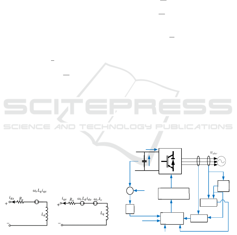
1) FCS MPC Power Converter
Rectifier is converter that converts voltage and
current alternating ( AC ) to voltage and current
direct (DC). Converter power used in research _
this isa converter full scale power because simple,
efficient and easy natural settings. Converter full
scale power used consist from converter rotor and
converter side grid side. Converter the side of the
rotor consists of from rectifier 3 - phase diode and
boost converter while converter the grid side is a
voltage source inverter (VSI)
Figure 3: Converter FCS MPC.
Reference current moment time short
(
𝐾+1
)
on
the current prediction block according to the
following equation:
𝑣
𝑖
Inverter
DC/AC
Grid
𝑣
𝑣
∗
𝑒
𝑖
∗
𝑖
∗
𝑣
𝑣
𝑖
𝑖
(𝑘 + 1)
𝑆
PI
Cost Function
Optimization
Predictive
Model
PLL
abc/dq
abc/dq
𝜃
iCAST-ES 2022 - International Conference on Applied Science and Technology on Engineering Science
360

𝑖
𝑑
∗
(
𝑘+1
)
=3𝑖
𝑑
∗
(
𝑘
)
−3𝑖
𝑑
∗
(
𝑘−1
)
−3𝑖
𝑑
∗
(
𝑘−2
)
(8)
𝑖
𝑞
∗
(
𝑘+1
)
=3𝑖
𝑞
∗
(
𝑘
)
−3𝑖
𝑞
∗
(
𝑘−1
)
−3𝑖
𝑞
∗
(
𝑘−2
)
(9)
Just like above, when prediction moment
(
𝐾+2
)
𝑖
𝑑
∗
(
𝑘+2
)
=3𝑖
𝑑
∗
(
𝑘+1
)
−3𝑖
𝑑
∗
(
𝑘
)
−3𝑖
𝑑
∗
(
𝑘−1
)
(10)
𝑖
𝑞
∗
(
𝑘+2
)
=3𝑖
𝑞
∗
(
𝑘+1
)
−3𝑖
𝑞
∗
(
𝑘
)
−3𝑖
𝑞
∗
(
𝑘−1
)
(11)
Current prediction moment
(
𝑘+1
)
𝑖
𝑑
(
𝑘+1
)
=3𝑖
𝑑
(
𝑘
)
−3𝑖
𝑑
(
𝑘−1
)
−3𝑖
𝑑
(
𝑘−2
)
(12)
𝑖
𝑞
(
𝑘+1
)
=3𝑖
𝑞
(
𝑘
)
−3𝑖
𝑞
(
𝑘−1
)
−3𝑖
𝑞
(
𝑘−2
)
(13)
Already know current from prediction, then
there is repair which current is the real current
compared with prediction current, for generated
current _ follow the equation below this:
𝑖
𝑑
𝑞
(
𝑡
)
=
𝐴
sin 𝜔𝑇
(14)
In time discrete, then:
𝑖
𝑑
𝑞
(
𝑘
)
=
𝐴
sin𝜔𝑇
𝑠
(15)
𝑖
𝑑𝑞
(
𝑘−1
)
=
𝐴
sin𝜔𝑇
𝑠
(𝑘 − 1)
𝑖
𝑑𝑞
(
𝑘−1
)
=
𝐴
sin 𝜔𝑇
𝑠
𝑘−𝜔𝑇
𝑠
=
𝐴
sin𝜔𝑇
𝑘cos𝜔𝑇
−
𝐴
sin𝜔𝑇
cos𝜔𝑇
𝑘
(16)
𝑖
𝑑𝑞
(
𝑘−2
)
=
𝐴
sin𝜔𝑇
𝑠
(𝑘 − 2)
𝑖
𝑑𝑞
(
𝑘−2
)
=
𝐴
sin 𝜔𝑇
𝑠
𝑘−2𝜔𝑇
𝑠
=
𝐴
sin𝜔𝑇
𝑘cos2𝜔𝑇
−
𝐴
sin2𝜔𝑇
cos𝜔𝑇
𝑘
(17)
From equation (16) we get
cos𝜔𝑇
𝑠
𝑘=
1
𝐴
sin 𝜔𝑇
𝑠
(
𝐴
sin 𝜔𝑇
𝑠
𝑘cos𝜔𝑇
𝑠
−𝑦(𝑘−1))
(18)
Equality (17) eliminated _
𝑦
(
𝑘−2
)
=
𝐴
sin𝜔𝑇
𝑘−2𝜔𝑇
=𝑖
(𝑘)cos2𝜔𝑇
−
𝐴sin2𝜔𝑇
𝐴sin𝜔𝑇
(𝑖
(𝑘)cos𝜔𝑇
−𝑖
(𝑘− 1))
= 𝑖
𝑑𝑞
(
𝑘
)
cos2𝜔𝑇
−
sin2𝜔𝑇
cos𝜔𝑇
sin𝜔𝑇
𝑖
𝑑𝑞
(
𝑘
)
+
sin2𝜔𝑇
sin𝜔𝑇
𝑖
𝑑𝑞
(𝑘 − 1)
(19)
Equality (19) simplified with suppose
cos2𝜔𝑇
𝑠
=𝑝
sin 2𝜔𝑇
𝑠
cos𝜔𝑇
𝑠
sin 𝜔𝑇
𝑠
=𝑞
And
sin 2𝜔𝑇
𝑠
sin 𝜔𝑇
𝑠
=𝑟
So t 𝑖
𝑑𝑞
(
𝑘−2
)
=𝑝 𝑖
𝑑𝑞
(
𝑘
)
−𝑞 𝑖
𝑑𝑞
(
𝑘
)
−
𝑟 𝑖
𝑑𝑞
(
𝑘−1
)
hat equation (19) could written repeat
be:
𝑖
𝑑𝑞
(
𝑘−2
)
=
(
𝑝−𝑞
)
𝑖
𝑑𝑞
(
𝑘
)
−𝑟𝑖
𝑑𝑞
(
𝑘−1
)
(
𝑝−𝑞
)
𝑖
𝑑𝑞
=−𝑟 𝑖
𝑑𝑞
(
𝑘−1
)
+𝑖
𝑑𝑞
(𝑘
−2)
𝑖
𝑑𝑞
(
𝑘
)
=−
𝑟
𝑝−𝑞
𝑖
𝑑𝑞
(
𝑘−1
)
+
1
𝑝
−
𝑞
𝑖
𝑑𝑞
(𝑘 − 2)
(20)
Equality (20) substituted will be:
𝑖
(
𝑘
)
=−
sin2𝜔𝑇
sin𝜔𝑇
cos2𝜔𝑇
−
sin2𝜔𝑇
cos𝜔𝑇
sin𝜔𝑇
𝑖
(
𝑘−1
)
+
1
cos2𝜔𝑇
−
sin2𝜔𝑇
cos𝜔𝑇
sin𝜔𝑇
𝑖
(𝑘 − 2)
𝑦
(
𝑘
)
=−
sin2𝜔𝑇
sin𝜔𝑇
cos2𝜔𝑇
−sin2𝜔𝑇
cos𝜔𝑇
𝑦
(
𝑘−1
)
+
sin𝜔𝑇
sin𝜔𝑇
cos2𝜔𝑇
−sin2𝜔𝑇
cos𝜔𝑇
𝑦
(
𝑘−2
)
𝑖
(
𝑘
)
=−
sin2𝜔𝑇
sin(𝜔𝑇
−2𝜔𝑇
)
𝑖
(
𝑘−1
)
+
sin𝜔𝑇
sin(𝜔𝑇
−2𝜔𝑇
)
𝑦
(
𝑘−2
)
𝑖
𝑑𝑞
(
𝑘
)
=−
sin 2𝜔𝑇
𝑠
−sin𝜔𝑇
𝑠
𝑖
𝑑𝑞
(
𝑘−1
)
+
sin 𝜔𝑇
𝑠
−sin𝜔𝑇
𝑠
𝑖
𝑑𝑞
(
𝑘
−2
)
𝑖
𝑑𝑞
(
𝑘
)
=
sin2𝜔𝑇
𝑠
sin 𝜔𝑇
𝑠
𝑖
𝑑𝑞
(
𝑘−1
)
−𝑖
𝑑𝑞
(
𝑘−2
)
(21)
𝑖
𝑑𝑞
(
𝑘+1
)
=
sin 2𝜔𝑇
𝑠
sin 𝜔𝑇
𝑠
𝑖
𝑑𝑞
(
𝑘
)
−𝑖
𝑑𝑞
(
𝑘−1
)
(22)
Wind Energy Conversion System Using Finite Control Set Method: Predictive Control Model Connected to the Grid
361

Repair current compare Among current that has
been predictable with generated current _ before enter
to in cost functions. Repair current here too can in
prediction moment 𝑖
𝑑𝑞
(
𝑘−2
)
.𝑖
𝑑𝑞
(𝑘 − 1) up to
𝑖
𝑑𝑞
(
𝑘+1
)
. From equations (22) and (13) then
obtained results prediction based on the forward euler
approach.
𝑢
∗
(
𝑘+1
)
𝑢
∗
(
𝑘+1
)
=
⎣
⎢
⎢
⎡
𝑅
−
𝐿
𝑇
−𝜔
𝐿
𝜔
𝐿
𝑅
−
𝐿
𝑇
⎦
⎥
⎥
⎤
𝑖
(
𝑘+1
)
𝑖𝑞
(
𝑘+1
)
+
⎣
⎢
⎢
⎡
𝐿
𝑇
0
0
𝐿
𝑇
⎦
⎥
⎥
⎤
𝑖
∗
(
𝑘+2
)
𝑖
∗
(
𝑘+2
)
+
0
𝜔
𝜑
(23)
after determine repair current and prediction
current, output from prediction that is cost function in
accordance with vector in the appropriate converter
with equality following:
𝑔=
|
𝑢
∗
(
𝑘+1
)
−𝑢
(𝑘 + 1)
|
+𝑢
∗
(
𝑘+1
)
−𝑢
(𝑘 + 1)
(24)
Matlab /Simulink programming is used for
demonstrate on the app use FCS MPC method. The
simulation results obtained with parameters like table
following this, Table 1 is the system parameters for
implementation of FCS MPC. Implementation
system could seen in Figure 4 , which is a flow chart
implementation . The stages in the flow chart first
from calculation current until with get cost function
value.
Table 1: System Parameter.
Parameter Unit Value
DC Voltage
𝑣
𝑑𝑐
900 V
Grid-voltage amplitude
𝑣
𝑔
230
√
2
Converter Side Inductor
𝐿
1
20 mH
Grid Side Inductor
𝐿
2
1.6 mH
Filter Capacitor 𝐶 65.25 𝜇𝐹
Capacitor Resistance
𝑅
𝑐
5Ω
3 RESULTS AND DISCUSSION
On research this conducted measurement speed wind
with use satellite nasa on the web
https://power.larc.nasa.gov/data-access-viewer/ on
site Cilacap State Polytechnic. Measurement Results
speed wind for 1 year in 2020 is shown in Figure 4
which is average profile in per month.
Figure 4: Average speed results wind in the district Cilacap.
Based on speed the wind in figure 4, the average
month speed at Cilacap State Polytechnic which is the
highest in the month December of 9.12 m/s and the
lowest speed in the month February of 5.34. The
average speed in 2020 is of 7.40 m/s and with a
median of 7.52. This data then processed for
determine the Weibull distribution at speed wind.
With speed maximum in month December of 9.12
m/s for determination of nominal mechanical power
on turbine speed wind like shown in figure 5.
Figure 5: Connection Among power mechanic turbine wind
and speed turbine wind.
Figure 6. Show Weibull distribution for take into
account condition wind external. The resulting power
output is results from the average value obtained by
the turbine wind. Election Weibull distribution can
model variance wind with utilise function from
density probability.
0 0.2 0.4 0.6 0.8 1 1.2 1.4
Turbine speed (pu of nominal generator speed)
-0.2
0
0.2
0.4
0.6
0.8
1
Turbine Power Characteristics (Pitch angle beta = 0 deg)
1 pu
Max. power at base wind speed (9.12 m/s) and beta = 0 deg
4 m/s
5.024 m/s
6.048 m/s
7.072 m/s
8.096 m/s
9.12 m/s
iCAST-ES 2022 - International Conference on Applied Science and Technology on Engineering Science
362

Figure 6: Weibull Distribution of Wind Speed.
After knowing profile energy the wind at the
Cilacap State Polytechnic, stages next enter into the
PMSG modelling for knowing comparison Among
speed wind and generator speed generated. The speed
of the generator depends on the wind speed obtained
by the wind turbine. As shown in Figure 7, the higher
the wind speed, the greater the power generated.
Figure 7: Comparison Wind speed and Generator Speed.
Figure 7 is comparison speed wind with generator
speed, speed wind taken in 2020, which is 5.34 m/s
min, 7.4 m/s average and 9.4 m/s max. Moment speed
wind at 5.34 m/s generator speed is 18 rad/s, when
speed wind 7.4 m/s generator speed of 31 rad/s and
moment speed wind 9.4 m/s generator speed of 50
rad/s. This result It is known in Figure 10 that the
more big wind so the more the speed of the rotor on
the generated generator is also large. Stages next that
is enter converter control. Key main for get results
voltage output from the converter that is from voltage
output rectifier shown in Figure 8.
Figure 8: Voltage Output Rectifier.
Figure 8 is voltage rectifier that will processed for
determine results from inverter output. Speed given
wind so that like picture 8 that is of 7.4 m/s according
to with monthly average in 2020. Voltage in the
direction shown in Figure 8, namely of 890 Volts with
the desired from voltage unidirectional as big as 900
volts or have steady state error of 1%.
Figure 9: Output Voltage Source Inverter.
For get voltage the output of the inverter depends
on 𝑣
𝑑𝑐
the DC link. How big is the DC input voltage it
will be the equivalent AC voltage. The inverter output
is not a pure sine wave but a sine signal of the form
box generated by switching power electronics
components, namely IGBT. Figure 9 shows output of
the inverter with apply FCS MPC method with
without a filter with an amplitude of 600 volts,
different fasa 120 °and a frequency of 50 Hz. Figure
10 shows voltage and current output of the phase
inverter. sine wave va that is as big as 600 volts and
he of 1200 Ampere.
4 CONCLUSION
By results research that has been conducted for
convert energy wind to energy electricity and apply
FCS-MPC method, first get speed data wind in 2020,
the minimum is 5.34 m/s, the average is 7.4 m/s and
Amplitude
Amplitude
Amplitude
Wind Energy Conversion System Using Finite Control Set Method: Predictive Control Model Connected to the Grid
363

the max is 9.4 m/s. Moment speed wind at 5.34 m/s
generator speed is 18 rad/s, when speed wind 7.4 m/s
generator speed of 31 rad/s and moment speed wind
9.4 m/s generator speed of 50 rad/s. For get voltage
the output of the inverter depends on 𝑣
𝑑𝑐
the DC link.
How big voltage DC input then will Becomes
equivalent AC voltage. Result of application FCS
MPC method with without filter get 600 Volt
amplitude, different fasa 120 °and a frequency of 50
Hz.
ACKNOWLEDGEMENTS
The author acknowledgements State Polytechnic of
Cilacap for supporting the author’s internal research
with the DIPA funding. The author thanks colleagues
who support and assist research directly.
REFERENCES
Al-falahi, M. D. A., Jayasinghe, S. D. G., & Enshaei, H.
(2017). A review on recent size optimization
methodologies for standalone solar and wind hybrid
renewable energy system. Energy Conversion and
Management, 143, 252–274. https://doi.org/10.1016/
j.enconman.2017.04.019
Ali, M., Haitao, Y., Yao, W., & Yilin, Y. (2021). Control
of linear generator based on hysteresis-SVPWM
current rectification and bidirectional buck/boost
converter used for energy storage. IET Renewable
Power Generation, 15(14), 3282–3295.
https://doi.org/10.1049/rpg2.12251
Atherton, J., Sharma, R., & Salgado, J. (2017). Techno-
economic analysis of energy storage systems for
application in wind farms. Energy, 135, 540–552.
https://doi.org/10.1016/j.energy.2017.06.151
Faisal, M., Hannan, M. A., Ker, P. J., Hussain, A., Mansor,
M. bin, & Blaabjerg, F. (2018). Review of energy
storage system technologies in microgrid applications:
Issues and challenges. IEEE Access, 6, 35143–35164.
https://doi.org/10.1109/ACCESS.2018.2841407
Generation, W. P., & Design, W. T. (2011). Wind power
generation and wind turbine design. In Choice Reviews
Online (Vol. 48, Issue 07). https://doi.org/10.5860/
choice.48-3904
Guo, L., Zhang, X., Yang, S., Xie, Z., Wang, L., & Cao, R.
(2017). Simplified model predictive direct torque
control method without weighting factors for
permanent magnet synchronous generator-based wind
power system. IET Electric Power Applications, 11(5),
793–804. https://doi.org/10.1049/iet-epa.2015.0620
IRENA. (2020). Global Renewables Outlook: Energy
transformation 2050. In International Renewable
Energy Agency (p. 292). https://www.irena.org/
publications/2020/Apr/Global-Renewables-Outlook-
2020
Lamsal, D., Sreeram, V., Mishra, Y., & Kumar, D. (2019).
Output power smoothing control approaches for wind
and photovoltaic generation systems: A review.
Renewable and Sustainable Energy Reviews, 113(July),
109245. https://doi.org/10.1016/j.rser.2019.109245
Mahela, O. P., & Shaik, A. G. (2016). Comprehensive
overview of grid interfaced wind energy generation
systems. Renewable and Sustainable Energy Reviews,
57, 260–281. https://doi.org/10.1016/j.rser.2015.12.0
48
Meghni, B., Dib, D., & Azar, A. T. (2017). A second-order
sliding mode and fuzzy logic control to optimal energy
management in wind turbine with battery storage.
Neural Computing and Applications, 28(6), 1417–
1434. https://doi.org/10.1007/s00521-015-2161-z
Multazam, T., Putri, R. I., Pujiantara, M., Priyadi, A., &
Mauridhi Hery, P. (2017). Wind farm site selection base
on fuzzy analytic hierarchy process method; Case study
area Nganjuk. Proceeding - 2016 International Seminar
on Intelligent Technology and Its Application, ISITIA
2016: Recent Trends in Intelligent Computational
Technologies for Sustainable Energy, 545–550.
https://doi.org/10.1109/ISITIA.2016.7828718
Nadour, M., Essadki, A., & Nasser, T. (2020). Improving
low-voltage ride-through capability of a multimegawatt
DFIG based wind turbine under grid faults. Protection
and Control of Modern Power Systems, 5(1).
https://doi.org/10.1186/s41601-020-00172-w
Purnata, H., Rameli, M., & Effendie Ak, R. (2017). Speed
control of three phase induction motor using method
hysteresis space vector pulse width modulation. 2017
International Seminar on Intelligent Technology and Its
Application: Strengthening the Link Between
University Research and Industry to Support ASEAN
Energy Sector, ISITIA 2017 - Proceeding, 2017-
Janua(Ilc), 199–204. https://doi.org/10.1109/
ISITIA.2017.8124080
Putri, R. I., Pujiantara, M., Priyadi, A., Ise, T., & Purnomo,
M. H. (2018). Maximum power extraction
improvement using sensorless controller based on
adaptive perturb and observe algorithm for PMSG wind
turbine application. IET Electric Power Applications,
12(4), 455–462. https://doi.org/10.1049/iet-epa.2017.0
603
Ren, G., Liu, J., Wan, J., Guo, Y., & Yu, D. (2017).
Overview of wind power intermittency: Impacts,
measurements, and mitigation solutions. Applied
Energy, 204(October), 47–65. https://doi.org/10.1016/
j.apenergy.2017.06.098
Tarisciotti, L., Zanchetta, P., Watson, A., Clare, J., Degano,
M., & Bifaretti, S. (n.d.). Modulated Model Predictve
Control (M 2 PC) for a 3-Phase Active Rectifier.
Teknologi, P., Indonesia, E., Surya, T., Charging, E.,
Pengkajian, P., Proses, I., Pengkajian, B., Bppt, T., &
Habibie, G. B. J. (n.d.). OUTLOOK ENERGI
INDONESIA 2021.
Wang, M., Mu, Y., Li, F., Jia, H., Li, X., Shi, Q., & Jiang,
T. (2020). State Space Model of Aggregated Electric
iCAST-ES 2022 - International Conference on Applied Science and Technology on Engineering Science
364

Vehicles for Frequency Regulation. IEEE Transactions
on Smart Grid, 11(2), 981–994. https://doi.org/
10.1109/TSG.2019.2929052
Yang, Y., Wen, H., & Li, D. (2017). A Fast and Fixed
Switching Frequency Model Predictive Control with
Delay Compensation for Three-Phase Inverters. IEEE
Access, 5, 17904–17913. https://doi.org/10.1109/
ACCESS.2017.2751619
Zhang, Y., Wu, X., Yuan, X., Wang, Y., & Dai, P. (2016).
Fast Model Predictive Control for Multilevel Cascaded
H-Bridge STATCOM with Polynomial Computation
Time. IEEE Transactions on Industrial Electronics,
63(8), 5231–5243. https://doi.org/10.1109/TIE.2016.25
72662
Zhang, Z., Fang, H., Gao, F., Rodriguez, J., & Kennel, R.
(2017). Multiple-vector model predictive power control
for grid-tied wind turbine system with enhanced steady-
state control performance. IEEE Transactions on
Industrial Electronics, 64(8), 6287–6298.
https://doi.org/10.1109/TIE.2017.2682000
Wind Energy Conversion System Using Finite Control Set Method: Predictive Control Model Connected to the Grid
365
