
Smart Control Ice Tube Machine Using PLC and HMI with
Superheat Method Based on Compressor Low Pressure Parameters
Basuki Winarno, Budi Triyono, Yuli Prasetyo, Agus Choirul Arifin, Yoga Ahdiat Fakhrudi,
Eva Mirza Syafitri and Muhammad Hanif Nur Kholiq
State Polytechnic of Madiun, Serayu Street No. 84, Madiun City, Indonesia
Keywords: Smart Control, Ice Tube Machine, Superheat, PLC, HMI.
Abstract: Ice tube is a variant of ice cubes in the form of a tube or cylinder that has a hole in the middle with certain
diameters and lengths. Ice tube machine is a cooling machine that has the main function of cooling substances
so that the temperature is lower than the ambient temperature. The main components of the ice tube machine
are the compressor, condenser, and evaporator as the working fluid that circulates on the parts of the ice tube
machine. However, the average ice tube machine in operation is carried out by human operators, this can slow
down the production process of the ice produced. Smart control system is needed so that ice production can
be maximized every day called Smart Control PLC (Programmable Logic Controller) Based Ice Tube
Machine. This control ice tube machine can work automatically and also no longer requires an operator in the
work process of making ice tubes and this control system can be designed according to the needs of the
machine. We can monitor the ice tube machine specifically when the machine process is working on the HMI
(Human Machine Interface). This can make it easier to operate the Ice tube Machine.
1 INTRODUCTION
Ice tube is a variant of ice cubes in the form of a tube
or cylinder with a hole in the middle with certain
dimensions, diameters and lengths. Ice tube is in great
demand by the public, in addition to its easy-to-use
shape to mix various foods and drinks. This ice tube
or ice crystal is more hygienic with a clearer and
neater appearance. With a very wide market share,
this ice making business can be said to be very
potential, still wide open and very promising.
Indonesia has many companies or home industries
that use tube ice as a temporary cooler when shipping
to various places (Triyono et al., 2019). Because it
will not be possible if the freezer is also included
during shipping. Thus, ice tube flakes are one of the
shortcuts needed during the delivery process of frozen
food or beverage products, so that the product will be
maintained at low temperatures, and of course the
freshness of the product will not be disturbed. In
addition to shipping, it can also be used for storage of
products and raw materials that will be used to make
these food products. At this time, the demand for tube
ice is very much in demand by the public. Therefore,
an ice tube maker was made that has a large income
capacity, in order to meet the needs of the community.
The current tube ice machine can produce
approximately up to 1 ton for 24 hours. With an ice
tube machine, the process of making tube ice does not
require a long time and the ice produced is more
hygienic (Eidan et al., 2021; Hervatte, 2021; Salim et
al., 2018). However, there will be not many people
who understand the working principle of this tube ice
machine, there must be an operator to run the ice tube
machine.
Program Logic Controller (PLC) is a tool that is
able to control the control system on a machine that
can be adjusted automatically (Prasetyo, Triyono, et
al., 2021). Human Machine Interface (HMI) is a
communication medium for the processes that occur
in the PLC (Mendoza et al., 2021; Prasetyo,
Hidayatullah, et al., 2021; Triyono et al., 2021). One
of the functions of HMI is as monitoring data that can
be designed according to the needs of the machine
used. PLC and HMI can be combined in the operation
of the tube ice machine. The ice tube machine can
work automatically and also no longer requires an
operator in the process of making tube ice. The
benefit of this PLC and HMI is that all the programs
we want can be set in the PLC, and we can monitor
specifically when the machine process works on the
404
Winarno, B., Triyono, B., Prasetyo, Y., Arifin, A., Fakhrudi, Y., Syafitri, E. and Kholiq, M.
Smart Control Ice Tube Machine Using PLC and HMI with Superheat Method Based on Compressor Low Pressure Parameters.
DOI: 10.5220/0011811200003575
In Proceedings of the 5th International Conference on Applied Science and Technology on Engineering Science (iCAST-ES 2022), pages 404-408
ISBN: 978-989-758-619-4; ISSN: 2975-8246
Copyright © 2023 by SCITEPRESS – Science and Technology Publications, Lda. Under CC license (CC BY-NC-ND 4.0)
HMI. This can facilitate the operation of the tube Ice
Machine.
2 MANUSCRIPT PREPARATION
2.1 Schematic Diagram
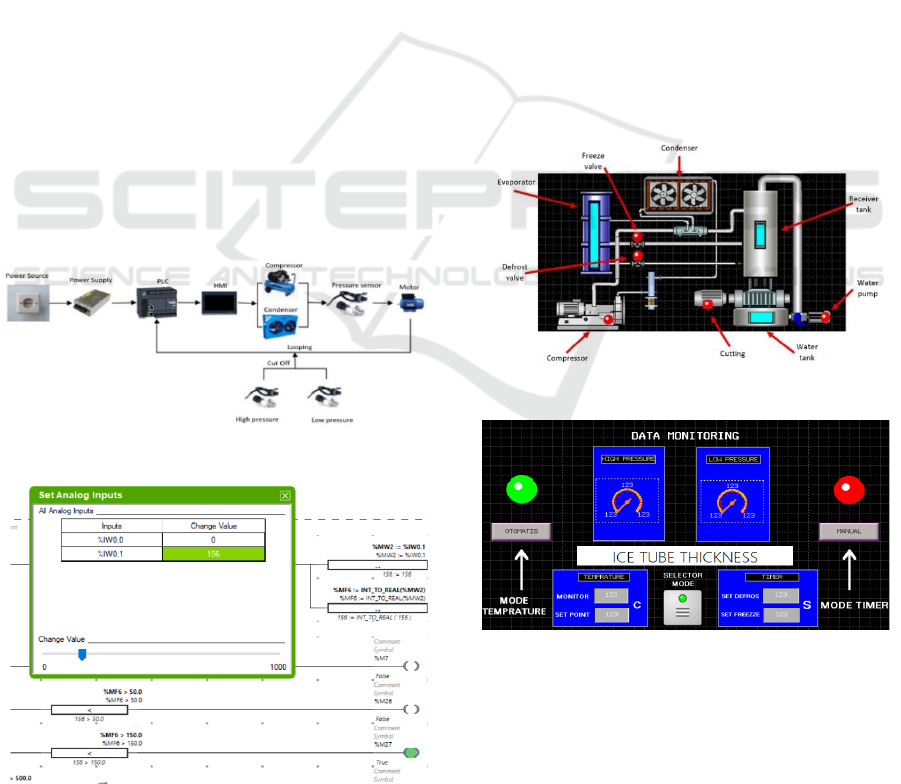
The design model of the PLC program is connected
to a 220V AC source as shown in Figure 1. To start
the circuit work, when the ON button is pressed it will
send a signal to the PLC and start the work process.
The stages of the ice tube machine work process are
starting with filling the water tank, then the tank
enters the freezing tank, namely the evaporator, along
with the compressor and condenser turning on. When
the filling is complete the Freeze process starts, this
process will stop when the temperature in the
evaporator reaches -9
0
C. When the sensor detects it,
the freeze process will stop and change to a defrost
process in which the evaporator will be sprayed with
hot wind to melt the ice cubes so that they are released
from the evaporator and will go down to the ice
storage container. The falling ice will be received by
the cutting motor and cut the ice into small shapes.
After the ice is cut out, the cutting motor will stop
then the working system will loop and start again at
filling the water tank with the compressor running
continuously.
Figure 1: Schematic diagram of ice tube machine.
Figure 2: PLC program reads the data from sensors.
Testing using a PLC Schneider Modicon with a
working step that is in the PLC program with
temperature mode. The temperature mode working
system is when the ON button is pressed, the
compressor, condenser, pump, freeze will work. Then
when the pressure sensor reads the pressure as shown
in Figure 2. Temperature – 9
0
C is configured as
pressure, the process will move to the second stage,
namely the defrost process and ice cutting.
2.2 HMI Design
Making the HMI program using the Schneider type,
namely HMI Magelis as shown in figure 3. The ice
tube machine works in 2 stages, namely stage 1 of the
ice making process and stage 2 of the ice cutting
process starting with the compressor on, followed by
the condenser, pump, and valve defrosting, then after
the sensor or timer works then stage 1 is complete and
turns off. Then stage 2 of the cutting process starts
with Valve defrost flashing (on – off repeatedly) after
a while followed by cutting lit at the specified time
and after the process is complete the machine will
loop back to the stage 1 process.
Figure 3: First view of HMI design of ice tube machine.
Figure 4: Second view of HMI design of ice tube machine.
Parts of tube ice machine
1. Compressor: serves to supply air to the engine.
2. Evaporator: air tank from freeze and defrost.
3. Condenser: a fan that serves to help the freeze
process
4. Receiver tank: ice tube formation.
Smart Control Ice Tube Machine Using PLC and HMI with Superheat Method Based on Compressor Low Pressure Parameters
405
5. Water pump: a water pump that delivers water to
the receiver tank
6. Water tank: a water reservoir.
7. Motor cutting: serves to cut the ice that falls from
Receiver tank.
8. Valve freeze: serves as a regulator of the cold
wind pressure opening valve for the
freezing process.
9. Valve defrost: serves as a regulator of the hot air
pressure opening valve for the
defrosting process.
The second display consists of set points for the
timer and temperature as well as monitoring for the
sensors used and then there are manual and automatic
buttons for switching panels/pages as shown in Figure
4.
3 RESULTS
3.1 Specification Data on Pressure
Sensor
The bit value is the configuration value to be entered
on the PLC. Here, the test is carried out when the
sensor is given wind pressure, the maximum bit value
that is read in the PLC is 106bit. Because the bit value
is unstable up and down, the bit value is rounded up
to 100. This value will later be used as the basis for
calculating the PLC configuration.
The sensor voltage value is the value that becomes
the basis for calculating other values. Here the test is
carried out when the sensor is given a maximum wind
pressure, the voltage value that can be read on the
sensor is 3 Volt with a maximum wind pressure of
110 Psi as shown in table 1.
1 psi = 0.06 bar
110 psi x 0,06 bar = 6,6 bar
3 V: 100 bit = 0,03 V
Output voltage in PLC is 110 psi: 100bit = 1.1bit
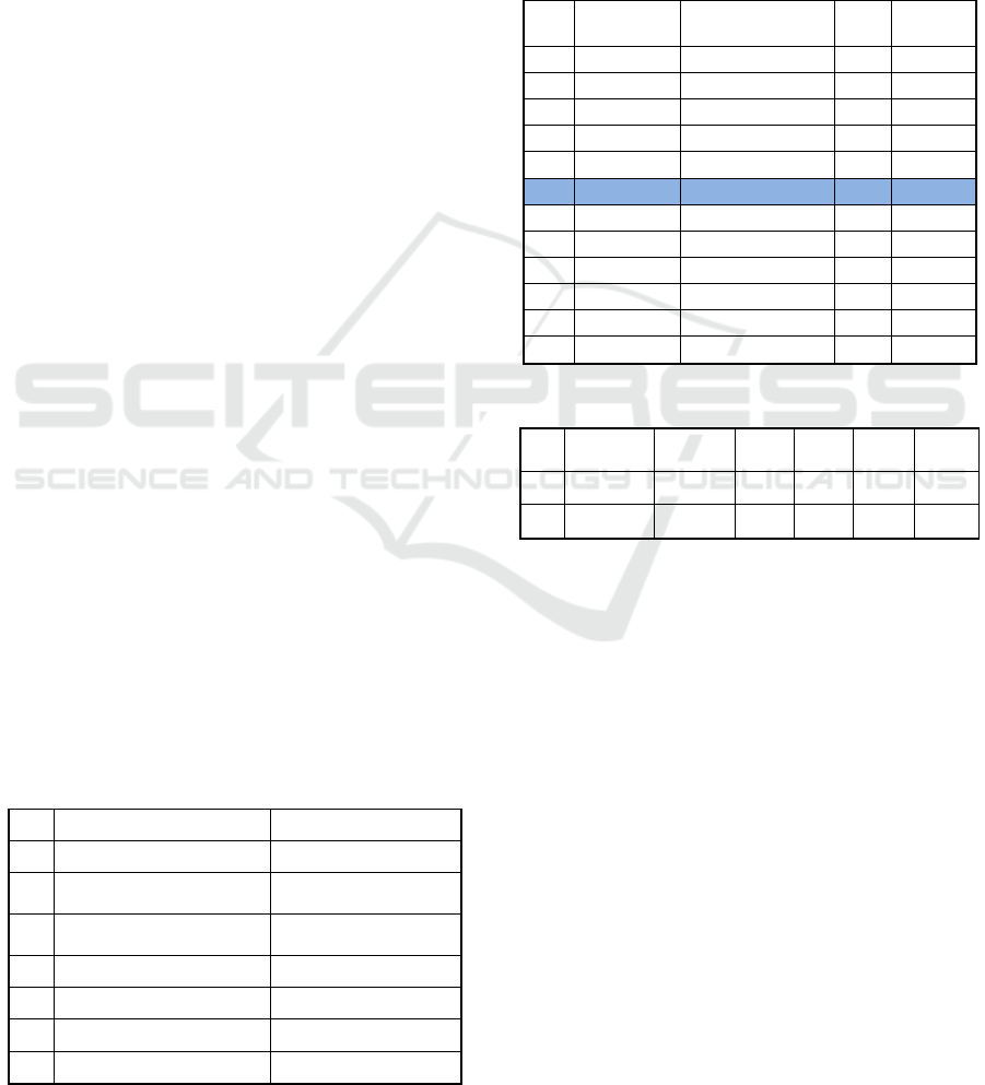
Table 1: Test Specification Data.
No Test Data Condition value
1 Pressure sensor capacity 110 Psi/6,6 Bar
2
Maximum output voltage
on senso
r
10-13 Volt
3
Maximum output pressure
on senso
r
110 Psi
4 Range bit read by sensor 100
5 Measurable voltage 3 Volt
6 1 bit in PLC 0,03 Volt
7 1.1 bit in PLC 1 Psi
Maximum low pressure on the compressor 110 psi =
11
0
C. Sensor read data on refrigerant R404A Ice tube
freezing temperature -9
0
Celsius = 50 Psi as shown in
table 2.
The working process of the tool is sequential with
stages starting with stage 1 of the freezing process
then after stage 1 is complete proceed to stage 2 of the
defrost process and the program will loop back to the
beginning as in table 3.
Table 2: Calibration sensor on compressor.
No
Pressure
(Psi)
Temperature
(
0
C)
Bit
Voltage
(volt)
1
1 -50 1,1 0,03
2
10 -35 11 0,33
3
20 -27 22 0,66
4
30 -20 33 0,99
5
40 -14 44 1,32
6
50 -9 55 1,65
7
60 -5 66 1,98
8
70 -1 77 2,31
9
80 3 88 2,64
10
90 6 99 2,97
11
100 9 110 3
12
110 11 220 3,3
Table 3: Calibration sensor on compressor.
Step Compressor Condenser Cutting Pump
V.
Freeze
V.
Defrost
1 1 1 0 1 1 0
2 1 0 1 0 0 1
3.2 PLC Program Testing in
Temperature Mode
System testing using PLC Modicon and HMI
Magelis. The test runs according to the working
stages of the tool. When the temperature mode must
wait until the adjusted temperature is reached. The
results of parameter testing on the PLC in temperature
mode are as in table 4.
Temperature Mode Stages:
a. Display the monitoring data page on the HMI by
pressing the DATA button.
b. Select in the selector to temperature mode.
c. Select the thickness of the ice tube on the
selection buttons provided on the HMI monitor,
namely 2cm, 3cm, 4cm, before running the
program.
d. When the selection is correct and the ON button
is pressed then the program can run. The effect
of temperature on the ice machine is that it can
iCAST-ES 2022 - International Conference on Applied Science and Technology on Engineering Science
406
adjust the thickness of the ice using the bit value
setting point on the PLC control in the HMI as
shown in table 5.
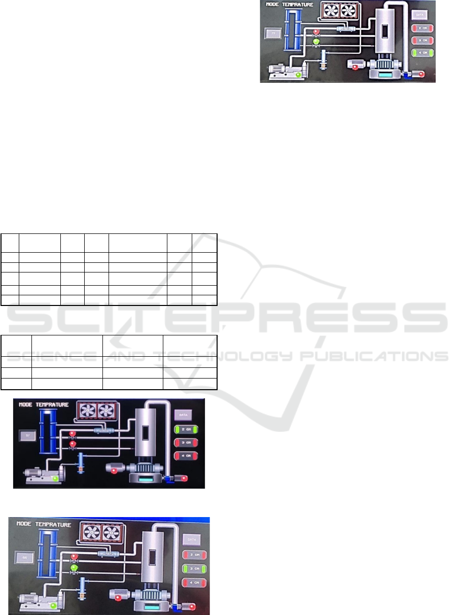
Set points are entered on the HMI monitor when you
want to make changes to the thickness of the ice tube.
The following is a display of the thickness of the ice
tube on the HMI monitor. When the ice thickness is
set to a thickness of 2 cm with a temperature of -1
0
C,
the sensor will read the bit value at 55bit and display
it on the HMI monitor as shown in Figure 5.
When the ice thickness is set at a thickness of
3 cm with a temperature of -5
0
C, the sensor will read
the bit value at 66bit and display it on the HMI
monitor as shown in Figure 6. When the ice thickness
is set at a thickness of 4 cm with a temperature of -
9
0
C, the sensor will read bit value in the 77bit number
and displayed on the HMI monitor figure 7.
Table 4: Test parameters on PLC in temperature mode.
No.
Pressure
(Psi)
High Low Temperature Step 1 Step 2
1 > 350 1 0 0 0 0
2 < 20 0 0 0 0 0
Temp. (
0
C) High Low Temperature Step 1 Step 2
1 < -9 0 0 0 1 0
2 > -9 0 0 1 0 1
Table 5: Result in mode temperature.
No
Thickness of
ice tube (cm)
Temperature
Bit value
in PLC
1 2 -1 55
2 3 -5 66
3 4 -9 77
Figure 5: HMI display when the ice tube thickness is 2 cm.
Figure 6: HMI display when the ice tube thickness is 3 cm.
Figure 7: HMI display when the ice tube thickness is 4 cm.
4 CONCLUSIONS
The ladder diagram program in the PLC and the tool
design display in the HMI work smoothly according
to the working stages of the ice tube machine. The
effect of temperature on the ice tube machine is as a
regulator of the thickness parameter on the ice tube in
temperature mode. The effect of wind pressure on the
ice tube machine is that it functions as a helper for the
freezing process and the melting process of tube ice
formation and is also one of the main components of
the tube ice machine.
ACKNOWLEDGEMENTS
Financial support for this paper is supported by the
Ministry of Education, Culture, Research and
Technology as well as the Collaboration of Dudi
Partners with the Education Fund Management
Institute (LPDP) through the 2021 Applied Scientific
Research Program Funding Program, for this
gratefully acknowledged.
REFERENCES
Eidan, A. A., Alshukri, M. J., Al-fahham, M., AlSahlani,
A., & Abdulridha, D. M. (2021). Optimizing the
performance of the air conditioning system using an
innovative heat pipe heat exchanger. Case Studies in
Thermal Engineering, 26, 101075. https://doi.org/
10.1016/j.csite.2021.101075
Hervatte, A. M. (2021). CFD Simulation of a Fin-Tube
evaporator under icing. 64.
Mendoza, E., Andramuño, J., Núñez, J., & Córdova, L.
(2021). Human machine interface (HMI) based on a
multi-agent system in a water purification plant. Journal
of Physics: Conference Series, 2090(1), 012122.
https://doi.org/10.1088/1742-6596/2090/1/012122
Prasetyo, Y., Hidayatullah, N. A., Artono, B., & Danu S, B.
(2021). Power Factor Correction Using Programmable
Logic Control Based Rotary Method. Journal of
Smart Control Ice Tube Machine Using PLC and HMI with Superheat Method Based on Compressor Low Pressure Parameters
407

Physics: Conference Series, 1845(1), 012045.
https://doi.org/10.1088/1742-6596/1845/1/012045
Prasetyo, Y., Triyono, B., & Kusbandono, H. (2021). Dual
Axis Solar Tracker Using Astronomic Method Based
Smart Relay. JAREE (Journal on Advanced Research
in Electrical Engineering), 5(1). https://doi.org/
10.12962/jaree.v5i1.156
Salim, A. T. A., Prasetyo, Y., & Fakhrudin, Y. A. (2018).
Study of Effect Comparison Thermoelectric
Characteristics of TEC and TEG by Considering the
Difference in Temperature and Variable Resistant. 3(4),
4.
Triyono, B., Prasetyo, Y., Subkhan, M. F., & Haryo, J. K.
(2019). Air Conditioning Modification into Crystal Ice
Machine with Fast Cooling Based on Smart Relay. 4(4),
3.
Triyono, B., Prasetyo, Y., Winarno, B., & Wicaksono, H.
H. (2021). Electrical Motor Interference Monitoring
Based On Current Characteristics. Journal of Physics:
Conference Series, 1845(1), 012044. https://doi.org/
10.1088/1742-6596/1845/1/012044
iCAST-ES 2022 - International Conference on Applied Science and Technology on Engineering Science
408
