
SCADA Control System Through Servomotor with PLC Monitored
by Software Application on Automatic Rolling Door
Imam Sutrisno
1
, Rahmadika Akbar
1
, Muhammad Reza Pahlevi
1
, Anisa Fitri Santosa
1
,
Perwi Darmajanti
1
, Didik Dwi Suharso
2
, Ignatius Kristianto Agung Nugroho
3
, Muji Setiyono
4
,
Fadel Muhammad
4
and Muhammad Idris
4
1
Politeknik Perkapalan Negeri Surabaya, Indonesia
2
Politeknik Pelayaran Surabaya, Indonesia
3
Sekolah Tinggi Ilmu Pelayaran, Indonesia
4
Politeknik Pelayaran Sorong, Indonesia
Keywords: SCADA, Servomotor, PLC.
Abstract: Automation is a basic technology in the digital era especially in industrial revolution 4.0 so as a human is a
shared responsibility between the workers and engineers who are specifically authorized to maintain the
stability of the technology. For example, a rolling door in an industrial warehouse is a way to make the
distribution possible from inside to outside the room or vice versa. But the implementation of the industrial
warehouse rolling door is still operated manually. So this study aims to create a control system for the
industrial warehouse rolling door like a Supervisory Control and Data Acquisition (SCADA) and it’s
controlled automatically through Servomotor with Programmable Logic Controller (PLC) and also to monitor
the system to inform certain conditions by using a software application. The purpose making of the automatic
rolling door for industrial warehouses with monitor software application itself is to construct everything from
the loading distribution to the shipment automatically without doing it manually and also at the same moment
can be monitored every time.
1 INTRODUCTION
The increasing need for automation in every life
aspect has made a lot of industry to develop many
automatic standards and implementations. The
engineer and the workers have a challenge so that it
meets the technical requirements as regulated by each
of the tools and component manual. The vehicle
should be considered first if it fits the regulation to
pass the rolling door and made it through the room for
loading. The automatic rolling door opens when the
door controller receives an activation signal from the
sensor and activates the gear motor to drive the belt
and pulley. When no one is detected inside the
activation area, the door starts closing after a
designated period of time. An automatic rolling door
operator is a set of driving devices and controllers that
opens/closes the door. It includes components such as
a gear motor and door controller. The power to the
door operator can be turned on/off easily during the
maintenance of the door. Activation sensors are used
to activate the door's openings and closings by
sending a signal to the door operator. The software
application is connected to every component of the
automatic rolling door so it can be controlled through
Human Machine Interface (HMI) and monitored in a
device such as a personal computer or laptop. The
challenges of the applied systems using this
technology have already been reported in some early
research. And some techniques used have been
considered useful candidates for the vehicle-to-
infrastructure context. Our paper proposed the
implementation of a basic rolling door controller as a
fixed infrastructure automated by common
distribution and transition vehicles used such as pick-
up trucks or cargo trucks.
Sutrisno, I., Akbar, R., Pahlevi, M., Santosa, A., Darmajanti, P., Suharso, D., Nugroho, I., Setiyono, M., Muhammad, F. and Idris, M.
SCADA Control System Through Servomotor with PLC Monitored by Software Application on Automatic Rolling Door.
DOI: 10.5220/0011812000003575
In Proceedings of the 5th International Conference on Applied Science and Technology on Engineering Science (iCAST-ES 2022), pages 437-441
ISBN: 978-989-758-619-4; ISSN: 2975-8246
Copyright © 2023 by SCITEPRESS – Science and Technology Publications, Lda. Under CC license (CC BY-NC-ND 4.0)
437
2 MANUSCRIPT PREPARATION
2.1 Literature Review
2.1.1 SCADA
SCADA (supervisory control and data acquisition) is
a category of software applications for controlling
industrial processes, which is the gathering of data in
real-time from remote locations in order to control
equipment and conditions. SCADA provides
organizations with the tools needed to make and
deploy data-driven decisions regarding their
industrial processes (Peter Loshin, 2021).
2.1.2 Servomotor
A servo motor is an electromechanical device that
produces torque and velocity based on the supplied
current and voltage. A servo motor works as part of a
closed loop system providing torque and velocity as
commanded by a servo controller utilizing a feedback
device to close the loop. The feedback device supplies
information such as current, velocity, or position to
the servo controller, which adjusts the motor action
depending on the commanded parameters
(Kollmorgen Experts, 2020).
2.1.3 Authors
A Programmable Logic Controller is a small
industrial computer originally designed to perform
the logic functions executed by electrical hardware
(relays, switches, and mechanical timer/counters), as
defined by The U.S. Department of Commerce
National Institute of Standards & Technology
(NIST). PLCs have evolved to control complex
processes and are used in supervisory control and data
acquisition (SCADA) systems and Distributed
Control Systems (DCS). PLCs are used in almost all
industrial processes. PLCs have user-programmable
memory for storing instructions for specific
functions, including I/O control, logic, timing,
counting, three mode (PID) control, communication,
arithmetic, and data and file processing. Unlike
SCADA and DCS, PLCs usually do not have a central
control server and HMI and, therefore, they
“primarily provide closed-loop control without direct
human involvement.”. This kind of automation
allows engineers with a limited knowledge of
computers and computing languages to operate the
systems easily, as PLCs are generally considered
intuitive (Cristina Tuser, 2022).
2.2 Research Method
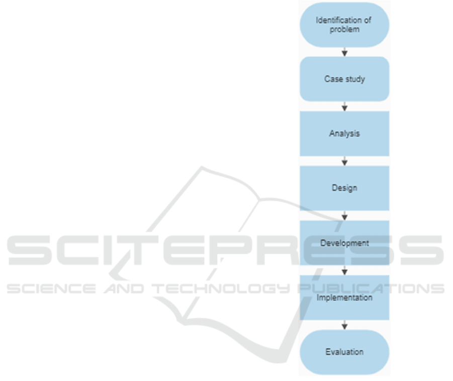
In the process of making a prototype, it is necessary
to design and flow to be able to know the
development and progress of the prototype as follows
Figure 1: Flowchart.
2.2.1 Identification of Problems
To start the method, first we should know the industry
need how the efficiency must be and how practically
could be of the use of rolling doors automatically.
Measure the width of the sensor placement and also
where the control panel should be placed. And then
configure the placement of the wiring how to connect
the control panel to the object.
2.2.2 Case Study
Based on the majority of user requests, this case
requires various actuator sensors and control systems
iCAST-ES 2022 - International Conference on Applied Science and Technology on Engineering Science
438

to run automatic rolling door systems such as load
cells, relays, mini-circuit breakers, motor drivers,
power supply, PLC, and HMI.
2.2.3 Analysis
The step requires designing a series of automatic
rolling door control systems, system design, design
a set of supporting tools, control panel design, and
diagram wiring. Also, there is an analysis of non-
functional requirements. Hardware: Personal
computer (PC/Laptop), communication cable,
control panel. Software: EasyBuilder Pro
application for HMI designing and connecting HMI
to the program, PANATERM application for
monitoring the Servomotor, FPWIN GR application
for the PLC programming, and AutoCAD
application for various designing (Sutrisno, 2019).
2.2.4 Design
A hardware design from control panel.
Figure 2: Control panel wiring.
The control panel contains a 24VDC power
supply, 6A mini-circuit breaker, Panasonic PLC
FP0R, PLC CPU, and terminals. The mini-circuit
breaker to turns on the power source. The Power
supply supplies the DC current to the PLC. Terminals
to connect various wiring.
Picture of one of the HMI design windows.
The HMI is designed to make it easier to control
and monitor the object. There are many various
windows included in the HMI display like parameter
window, monitor window, input window, and many
others.
Figure 3: HMI Display.
2.2.5 Development
Hardware and software development as follows:
Determine which components to use, designing
wiring, make ladder program on PLC FP0R, creating
HMI display for operator convenience, trial run of the
entire automatic rolling door system such as checking
servomotor, PLC, and also HMI.
2.2.6 Implementation
At this stage, testing of the tool and a trial run of the
servomotor through the PANATERM application is
carried out by running for several hours to ensure that
the servomotor is safe. Checking the program if it
connected with sensor & actuator. If all the
requirement is ready and safe, the simulation can be
started. The vehicle will drive through the near edge
of the door. And if the sensor detected, the
servomotor will work which means the rolling door is
open (Sutrisno, 2014).
2.2.7 Evaluation
This evaluation stage where the author sees the
success rate of the simulation after passing the trial
and will be used to develop the next automatic rolling
door process.
2.3 Program Logic Ladder
The following figure shows the program used to
program the PLC FP0R.
Figure 4: Command button rung network.
SCADA Control System Through Servomotor with PLC Monitored by Software Application on Automatic Rolling Door
439
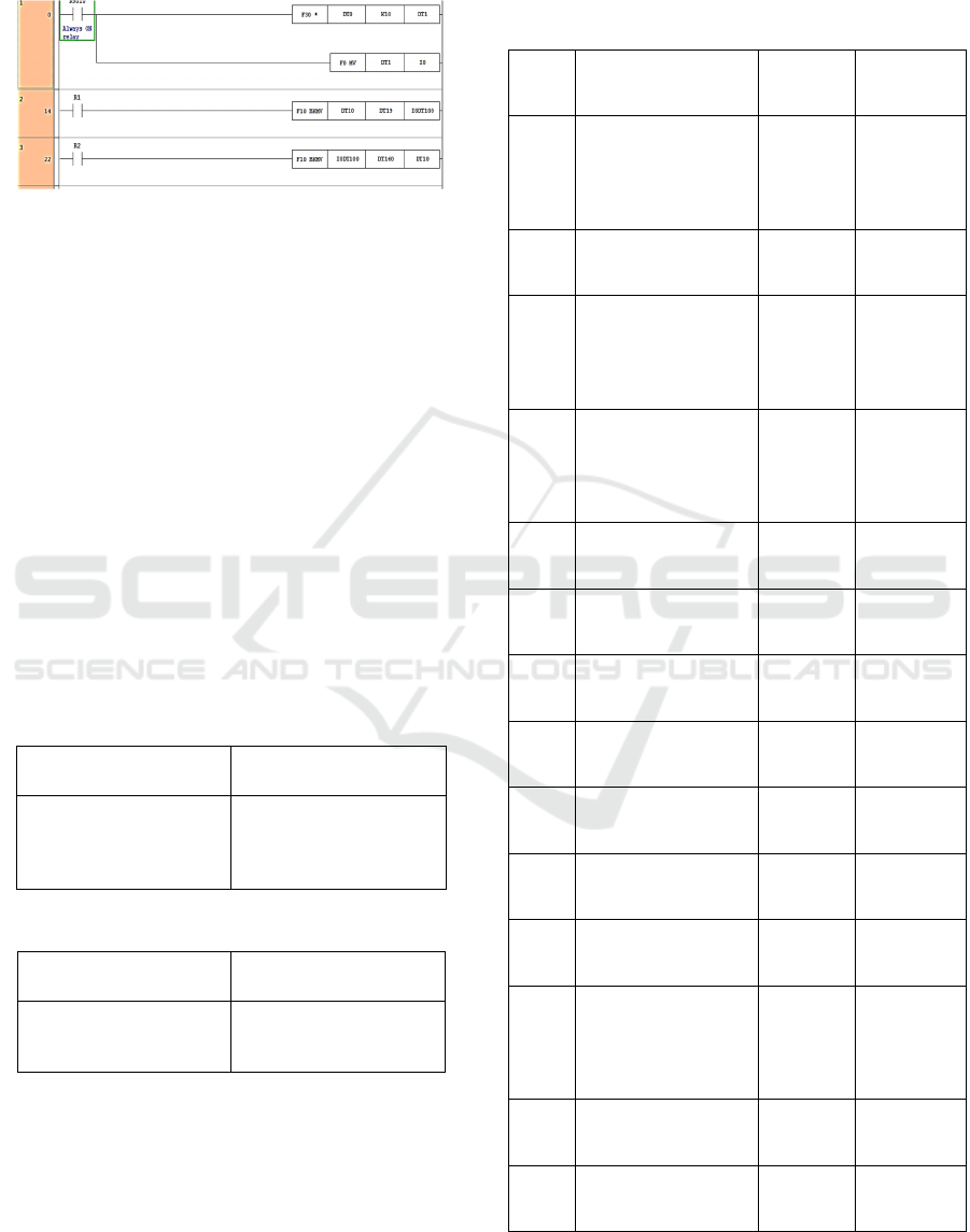
The created program is centered on a pushbutton from
start button, stop button, emergency button, and reset
button.
Figure 5: Indexing data rung network.
In the indexing data program, the use is for saving and
loading data when the simulation is working
including the day, time, and date. The data can be also
removed or reset to make new data. The data will be
displayed on HMI itself.
2.4 Alarm Display List
Alarm display list can be viewed in PANATERM
application. The alarm list contains various past
machine error from the servomotor so we can monitor
and know the problem what causes the error. This is
the alarm list from the recent simulation.
Model name: MDDLN45SG011
Print Date: July 27, 2022 13:44:27
Serial No: 18050079
Table 1: Now Error.
Protect Function
Error CD
Encoder communication
disconnect error
protection
21.0
Table 2: Now Warning.
Protect Function
Error CD
Encoder communication
warning
A4
When the simulation start and the device/laptop is
connected to the control panel via a communication
cable, we can open the PANATERM application to
monitor and look at the alarm list history from the
past to the present. The monitor displays from the
now error, now warning, and past error history. With
the alarm list, we can see why and how the simulation
work or maybe there is an error so we can find the
problem from the list and find the solution to make it
work again like running a jog in a trial run.
Table 3: Past Error History.
Hist.
Protect Function
Error CD
Power Of
Time[h]
1
Encoder
communication
disconnect error
protection
21.0
12926
2
Over-load
protection
16.0
12926
3
Encoder
communication
disconnect error
protection
21.0
12926
4
Encoder
communication
disconnect error
protection
21.0
12926
5
Over-load
protection
16.0
12926
6
Over-load
protection
16.0
12926
7
Overload protection
16.0
12926
8
Over-load
protection
16.0
12926
9
Over-load
protection
16.0
12926
10
Over-load
protection
16.0
12926
11
Over-load
protection
16.0
12926
12
Encoder
communication
disconnect error
protection
21.0
12926
13
Over-load
protection
16.0
12926
14
Overload protection
16.0
12926
iCAST-ES 2022 - International Conference on Applied Science and Technology on Engineering Science
440

3 CONCLUSIONS
With the simulation that has been cleared and how the
system work, the level of security and effectiveness
in an industrial warehouse can be further increased
and allows the industrial product distribution to
become fastly automatic and also can be reliable.
Because this system can facilitate the warehouse
worker and distribution transition allowed it to be
more practical in these day technology and has very
minimum of failure and work accidents. Meanwhile,
when using this system, the message can be
maintained until the situation is under control and all
of the workers are ensured. This system could be
implemented to Society 5.0. Where all working
activities can be improved effectiveness and
efficiency with the control system more precisely and
quickly than before.
REFERENCES
Loshin, Peter (2021). What is a SCADA (supervisory
control and data acquisition) and how does it work? In
https://www.techtarget.com. Accessed July 30, 2022.
Kollmorgen Experts (2020). How Servo Motors Work. In
https://www.kollmorgen.com. Accessed July 30, 2022.
Tuser, Cristina (2022). What is a Programmable Logic
Controller (PLC)? In https://www.wwdmag.com.
Accessed September 19, 2022.
Sutrisno, Imam (2019). Design of Pothole Detector Using
Gray Level Co-occurrence Matrix (GLCM) And Neural
Network (NN). IOP Conference Series: Materials
Science and Engineering.
Sutrisno, Imam (2014). Nonlinear Model-Predictive
Control Based on Quasi-ARX Radial-Basis Function-
Neural-Network. 2014 8th Asia Modelling Symposium
Sutrisno, Imam (2009), Pemrograman Komputer Dengan
Software Matlab disertai contoh dan aplikasi skripsi
dan thesis. ITS Press.
SCADA Control System Through Servomotor with PLC Monitored by Software Application on Automatic Rolling Door
441
