
Increased Production Capacity of Semi-Automatic Lens Pressing
Machine with Arduino Control Pneumatic Drive in the Type-045
Head Lamp Assembly Process
Eko Saputra, Yusuf Herlambang and Abdul Alfauzi
Politeknik Negeri Semarang, Semarang, Jawa Tengah, Indonesia
Keywords: Penekan Lensa, Head Lamp, Pneumatik, Arduino.
Abstract: Pressing the lens of the Head Lamp 045 or HL-045 product manually using both hands of the operator may
cause uneven compression. The manual process also often causes bottlenecks (time delays), also has an impact
on "Not Good" products and the HL-045 product production planning target is not achieved in the Industry.
The purpose of this research is to increase the productivity of the manufacture of HL-045 with the innovation
of a semi-automatic lens pressing machine to press the upper jig. The research method used is RCA (root
cause analyze) with the following stages: problem identification, problem determination, problem
understanding, corrective action, and system monitoring. Lens pressing machine testing was carried out using
3 pressure parameters, namely 0.3, 0.4 and 0.5 MPa with 30 trials each to obtain data on the lens pressing
process time. The test results show that the best test is at a pressure of 0.5 MPa with a lens pressing process
time of about 3.63 seconds. The conclusion of this study is that the semi-automatic lens pressing machine that
was made was able to increase production capacity by about 8.72% (initial 493 pcs/day to 536 pcs/day) and
reduce the assembly process time of the HL-045 product by 7.98% (initial 109.33 seconds to 100.6 seconds).
1 INTRODUCTION
PT. Indonesia Stanley Electric (ISE) is a
manufacturing company that produces lamps for the
application of two-wheeled and four-wheeled
motorized vehicles. The lamp parts produced include
Housing, Reflector, Extension, Lens, and Inner Lens.
The high demand from customers both in terms of
quantity and quality, then PT. Indonesia Stanley
Electric must implement good production management
standards so that production targets can be achieved.
Based on the method, the assembly process of a
product is divided into two, namely manual assembly
and automatic assembly. Manual assembly is an
assembly whose operation process is done
conventionally without special tools. Automated
assembly is an assembly that is done with automated
systems such as automation and requires more
specialized tools. (Ilyandi, 2015).
The implementation of the automation assembly
system in the line-lamp-assy has not been carried out
thoroughly. For example, the process of pressing the
lens on the line-lamp-assy of the HL type 045 product
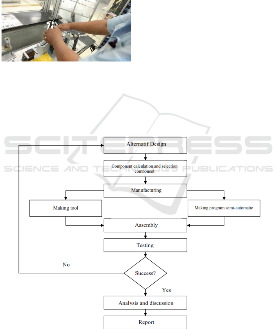
is still done manually, see Figure 1. This makes it
difficult for the operator during the manual lens
pressing process and the pressure applied to the lens
pressing process is uneven. This also resulted in "Not
good" product quality and frequent bottlenecks or
time delays that were not in accordance with the
predetermined time standard so that the HL-045
production target was not achieved.
In addition, the HL-045 production plan has a
production target in 1 working day of 540 parts/day.
Meanwhile, the actual production of HL-045 was 493
parts/day or 97.22% of the predetermined target.
Based on these data, it can be concluded that the
production planning of HL-045 has a problem,
namely a decrease in effectiveness and productivity.
In order to solve these problems, solutions and
innovations based on automation systems are needed,
namely through the design of a semi-automatic lens
pressing machine with a pneumatic drive based on
Arduino control. Arduino IDE is sophisticated
software and can be programmed using the C
programming language (Barret, 2011).
This research describes a semi-automatic lens
pressing machine system with pneumatic drive based
on Arduino control (Croser et al., 2002; Darto et al.,
Saputra, E., Herlambang, Y. and Alfauzi, A.
Increased Production Capacity of Semi-Automatic Lens Pressing Machine with Arduino Control Pneumatic Drive in the Type-045 Head Lamp Assembly Process.
DOI: 10.5220/0011875400003575
In Proceedings of the 5th International Conference on Applied Science and Technology on Engineering Science (iCAST-ES 2022), pages 719-725
ISBN: 978-989-758-619-4; ISSN: 2975-8246
Copyright © 2023 by SCITEPRESS – Science and Technology Publications, Lda. Under CC license (CC BY-NC-ND 4.0)
719
2015; Dindorf et al., 2017; Gupta et al., 2013; Junaidi
et al., 2018). This study also displays innovations
based on automation systems to increase the
effectiveness and productivity of HL-045 at PT.
Indonesia Stanley Electric. The machine is then
pressure tested to get the press time data.
Figure 1: Manual Lens Pressing Process.
The purpose of this research is to design and
manufacture a semi-automatic lens pressing machine
with a pneumatic drive based on Arduino control to
increase production capacity in the HL-045 assembly
process at PT. Indonesia Stanley Electric and to
determine the performance of the lens pressing machine
by comparing the differences in production results in
the HL-045 assembly process before and after the
design of the semi-automatic lens pressing machine.
2 MATERIAL AND METHOD
2.1 Method
Root Cause Analysis (RCA) is a method for finding a
problem or non-conformity in order to get to the root
cause of the problem. This method is used in order to
fix or eliminate the cause of the problem and prevent
the problem from recurring (Vorley, 2008).
Identification of root causes can be found by the
process of making fishbone diagrams. Fishbone
diagrams are a technique used for more complex
RCAs. This type of diagram identifies all the
processes and potential factors that can contribute to
the problem. Fishbone diagram technique is used to
describe the research process and to analyze the
factors that influence the problem in the lens pressing
process of the HL-045 line-lamp-assy product at PT.
Indonesia Stanley Electric covers man, method,
material, machine, money and environment.
Figure 2: Flow chart of design product.
iCAST-ES 2022 - International Conference on Applied Science and Technology on Engineering Science
720
Corrective action that serves to realize the design
concept that has been made into several alternative
designs. Then one of the best designs is chosen from
several alternative designs that have been made. The
selected design is then analyzed with mathematical
calculations on the material or components that will
be used in the manufacture of the lens pressing
machine. This design also adopted the process of
design product by (Cross, et al. 2000). Figure 2 is a
design flow diagram in the manufacture of a semi-
automatic lens pressing machine.
2.2 Design
The first step in designing a semi-automatic lens
pressing machine by using design software of
Solidworks (Dassault systems, 2015) is to activate
the vacuum ejector by turning the switch on first to
attach the HL-045 lens product to the upper jig. A
vacuum ejector is a device used to convert blowing
power into suction by creating a vacuum, so that this
allows the system to attract a desired workpiece
(Syahril, 2018). After the vacuum ejector is active,
the next step is to press the push button on the
microcontroller box. When the push button is pressed,
the reed switch sensor mounted on the upper
pneumatic cylinder will detect the initial piston
stroke, so that the piston will push the upper jig down
until the piston step is detected by the reed switch
sensor mounted on the bottom of the pneumatic
cylinder.
When the piston stroke has been detected on the
lower reed switch sensor, the lower reed switch
sensor is automatically activated while the upper reed
switch sensor and vacuum injector have been
deactivated by the Arduino microcontroller
command. When the lower reed switch sensor has
detected the piston step will stop or delay for 1 second
for the process of pressing the lens on the 045
reflector head lamp which is already installed on the
lower jig. After the lens pressing process is complete,
the piston will return to its initial position and activate
the upper reed switch sensor and vacuum ejector.
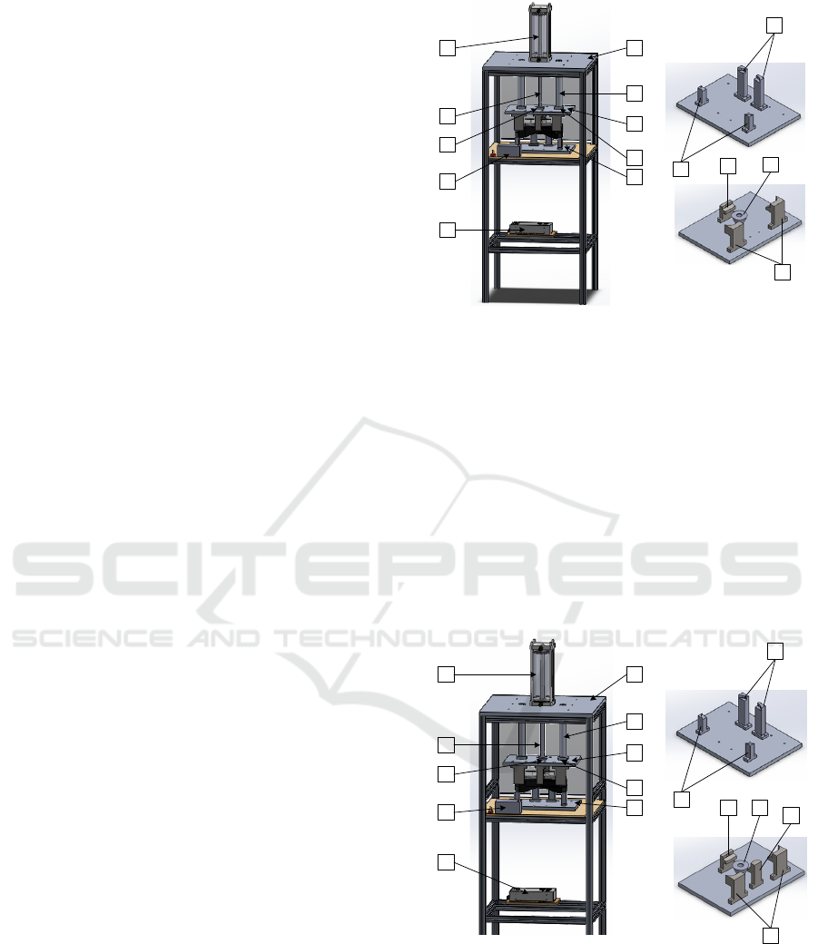
The advantages of this alternative design I have
several advantages, namely: it has a simple shape,
does not require a lot of material, affordable
manufacturing costs. As for the drawbacks, the upper
jig only has 3 stays to place the lens when the lens
pressing process takes place which is considered
imperfect in the gripping process, and there is no
retainer on the right and left sides so that the
construction strength of the lens pressing machine is
considered less strong.
A
I
H
B
J
F
G
C
D
E
L
K
M
N
0
Figure 3: Alternatif design 1.
The work steps of alternative design II are the same
as alternative designs I, namely the process of
suppressing the semi-automatic lens is controlled
through the Arduino microcontroller with the help of
a reed switch sensor to detect the piston stroke. The
advantage of alternative design II is that the machine
construction is stronger because of the holder on the
right and left side of the lens pressing machine, the
process is easier and the vacuum gripping area is
wider with the 4 stays on the upper jig. while the
disadvantage of alternative design II is that it requires
more material so that the manufacture becomes more
expensive.
A
I
H
B
J
F
G
C
D
E
L
K
M N
O
P
Figure 4: Alternatif desain 2.
The work steps of alternative design III are the same
as alternative designs I and II, namely the process of
suppressing the semi-automatic lens is controlled
through the Arduino microcontroller with the help of
a reed switch sensor to detect the piston stroke. The
advantage of alternative design III is that the vacuum
gripping area is wider with 4 stays on the upper jig so
Increased Production Capacity of Semi-Automatic Lens Pressing Machine with Arduino Control Pneumatic Drive in the Type-045 Head
Lamp Assembly Process
721
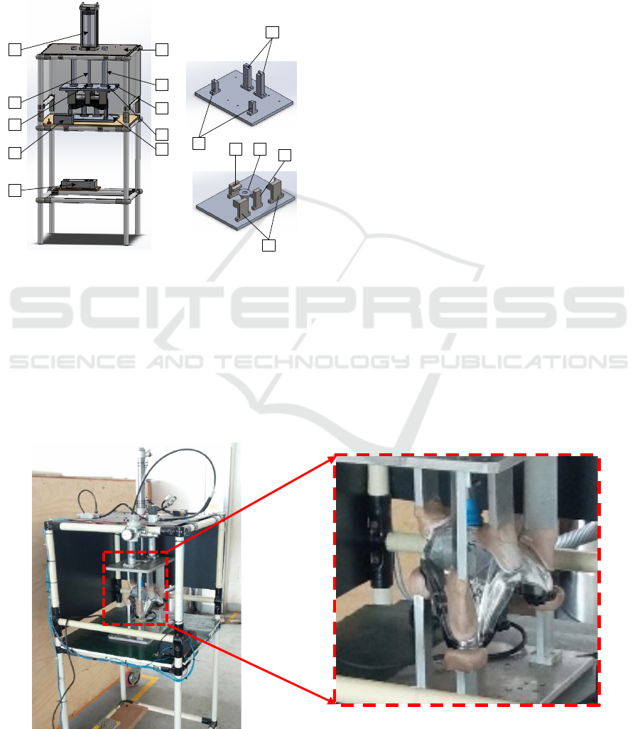
that it can grip the lens maximally and the machine
manufacture is much cheaper because it uses ivony
pipe material for the lens sealing machine frame.
While the disadvantage of alternative design III is that
the construction strength is less strong than
alternative design II, but it is still safe to use on semi-
automatic lens pressing machines and the process is
more difficult than alternative design II.
A
I
H
B
J
F
G
C
D
E
L
K
M N
O
P
Figure 5: Alternatif desain 2.
2.3 Testing
The test was carried out using 3 pressure variations to
determine the best pressure so that the lock on the 045
head lamp product could lock optimally and the semi-
automatic lens suppressor cycle time test was carried
out by observing the HL-045 assembly process.
This process is carried out by calculating the cycle
time of the lens pressing process and the production
capacity of the HL-045, then comparing before and
after the semi-automatic lens pressing machine so that
the success rate of the solution that has been
implemented can be seen. After that, control of the
tool needs to be done to determine the success rate of
whether the solutions that have been implemented can
solve the problem and do not cause new problems.
3 RESULT AND DISCUSSION
3.1 Mesin Penekan Lensa Semi
Automatic
Based on the results of the analysis of the design and
work processes carried out, a semi-automatic lens
pressing machine with a pneumatic drive based on
Arduino control is produced in the HL-045 assembly
process which has dimensions of 550 mm x 580 mm
x 1285 mm, see Figure 6. All of the machine element
selection follows the text book of (Khurmi et al.,
2005). This machine uses Pneumatic Solenoid valve
2/2 way: Airtac 1/8". DC 12V (Max Pressure 1.0
Mpa) and Solenoid valve 5/2 way: Airtac 1/8” Single
Coil DC 12V (Max Pressure 1.2
Mpa). Pneumatic Cylinder: SMC 32 x 160 (Max
Pressure 1.0 Mpa. Regulator / Pressure valve: SMC
ARP 20 (Set Pressure 0.008 to 0.6 Mpa). Vacuum
Ejector: Pamy CV 05 – HS 1/4" (Max Vacuum
87Kpa). Suction Cup: UT-SN-F20-TPU50-
1/8AG/M5IG-FIL Microcontroller: Arduino Nano
Atmega 168 (Work Voltage 5 volts).
Figure 6: The prototype of of Semi-Automatic Lens Pressing Machine.
iCAST-ES 2022 - International Conference on Applied Science and Technology on Engineering Science
722

3.2 Pressure Testing
The semi-automatic lens pressing machine was tested
with pressures of 0.3, 0.4, and 0.5 Mpa. The first test
data obtained is shown in Figure 7. Based on the data
obtained from the test results of 3 pressure variations
where one pressure variation was carried out 30 times
the lens suppression process experiment, then
different time results were obtained based on the
compressor pressure parameters that were working or
applied. Tests with a pressure of 0.5 Mpa, namely the
maximum safe pressure of the cylinder that is applied
to be the fastest time and there is no Noot Good (NG)
product compared to other pressures below it.
Figure 7: Alternatif desain 2.
3.3 Time Pressing after Impovement
The process of taking lens suppression data after the
improvement is carried out using a stopwatch when
the production process of the 045 type head lamp is
in progress. Table 1 shows the data on the time of
pressing the lens after the improvement obtained.
Table 1: Lens Pressure Time Data after Improvement.
N
o Procces Waktu
1 Installation of Qushion 3.64
2
H
oulder Caulkin
g
6.10
3
H
otmel
t
25.86
4 Lens Press 10.05
5 Installaation of SQ nu
t
6.44
6 Installaation of Bulb HL 4.32
7 Installaation of Cord Cp 6.94
8 Li
g
htin
g
Chec
k
22.56
9 Stampin
g
4.28
10 Visual Chec
k
10.41
Total 100.60
3.4 Comparison of Process Time
Before and after Improvement
Lens compression time data after Improvement The
research test of this semi-automatic lens pressing
machine with a pneumatic drive based on Arduino
control has been carried out using 3 pressure
variations, namely 0.3 Mpa, 0.4 Mpa, and 0.5 Mpa.
Testing with a pressure of 0.5 Mpa is the best test that
produces the fastest time and there is no NG product
compared to other pressures. Based on Figure 8 and
Table 1 it can be seen that the comparison of the 045
type head lamp assembly process before the
improvement activity was carried out with the
assembly process after the improvement activity was
carried out with the semi-automatic lens pressing
machine as shown in the figure below.
Based on Figure 8, it can be done analysis of
different work processes before and after
improvement. The difference lies in the 4th working
process, namely the lens suppression process which
previously took 18.78 seconds and after modification
it became 10.05 seconds. The graph shows that the
semi-automatic lens pressing machine with an
arduino-based pneumatic drive, in the 045 head lamp
assembly process experienced a decrease in cycle
time from 109.33 seconds to 100.6 seconds or 7.98%.
3.5 Productivity Cycle Time
Calculation Before Improvement
Time Active working hours at PT. Indonesia Stanley
Electric, which is Monday - Friday with an effective
time of 8 hours a day. Meanwhile, Saturday and
Sunday are taken to fill the overtime or overtime
schedule to meet production targets that cannot be
achieved with work activities. The following is the
calculation of the actual production amount in the 045
type head lamp assembly process before the
improvement is carried out by knowing the cycle time
of the lens suppression process before the
improvement is 109.33 seconds. The following is
Table 2 comparison before and after the improvement
of the manual lens pressing process.
0
1
2
3
4
5
6
0.3 0.35 0.4 0.45 0.5
Time (second)
Pressure (MPa)
Increased Production Capacity of Semi-Automatic Lens Pressing Machine with Arduino Control Pneumatic Drive in the Type-045 Head
Lamp Assembly Process
723
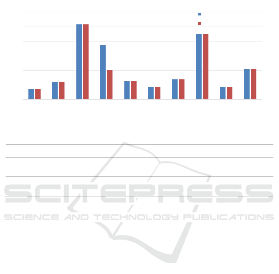
Figure 8: Comparison before and after Improvement.
Table 2: Comparison before and after Improvement.
Shift (hours)
Production
ca
p
acit
y
Average
p
roduction time
Performance
Before
Improvement
Shift 1 (8hour)
Shift 2 (7hour)
Total (15hour)
263
230
493
109.33 baseline
After
Improvement
Shift 1 (8Jam)
Shift 2 (7Jam)
Total (15Jam)
286
250
536
100.6
Cycle time - 7.98 % from actual
Produktivitas – 8,72 % from actual
Based on the data obtained from the test results of
3 pressure variations where one pressure variation
was carried out 30 times the lens suppression process
experiment, then different time results were obtained
based on the compressor pressure parameters that
were working or applied. Tests with a pressure of 0.5
Mpa, namely the maximum safe pressure of the
cylinder that is applied to be the fastest time and there
is no Not Good (NG) product compared to other
pressures below it.
The failure to achieve production results was
caused by obstacles in the assembly process of the
HL-045 product. The obstacles that occurred were in
the form of a bottleneck (time delay) in the assembly
process, resulting in a significant difference between
the actual time and the standard time set. Based on the
study time that has been carried out on the HL-045
assembly process, it is known the cause of the
obstacles that occur, namely the lens suppression
process. The average time needed to carry out the
pressing process is 12.56 seconds. This time is very
different from the standard time that has been set,
which is 3.55 seconds.
Based on the understanding of the problem, the
potential sources that cause problems are man,
material, method, money, machine and environment.
Sources caused by the man factor itself arise due to
the level of fatigue, work spirit and skills of each
operator. The difference in assembly time that has
been carried out by each operator is not too significant
but there is a large enough time difference with the
time set. Sources caused by material factors arise due
to the presence of NG material produced by the
plastic injection and evaporation division, resulting in
material shortages in the lamp assy division.
Therefore, there is a need for a double check process
in the division before the lamp assy.
The process of pressing the lens which is still
done manually results in bottlenecks (time delay) and
an increase in cycle time so that it has an impact on
not achieving the target production planning of the
045 head lamp. The manufacture of a semi-automatic
lens pressing machine with pneumatic drive is the
action taken to solve the existing problems. so that it
can increase the cycle time and productivity of the
HL-045. Environmental conditions can affect the
morale of each operator, besides that the quality of
product hygiene is also influenced by the existing
production environment. Therefore, each operator is
required to use special shoes in order to maintain the
cleanliness of the existing production environment.
Some of the proposed alternative designs are assessed
0
5
10
15
20
25
30
Pasang
Qushion
Houlder
Caulking
Hotmelt Lens
Press
Pasang
SQ nut
Pasang
Bulb HL
Pasang
Cord Cp
Lighting
Check
Stamping Visual
Check
Times (s)
Sebelum Improvement
Sesudah Improvement
iCAST-ES 2022 - International Conference on Applied Science and Technology on Engineering Science
724

based on the quality of the results, manufacturing
costs, construction, ergonomics and workmanship.
Based on the assessment that has been carried out, it
is found that the three alternative designs have the
highest rating, and the three alternative designs were
chosen to be the design used. Calculation of material
strength is carried out to determine material
specifications that are safe to use on lens pressing
machine components including: calculating axial
forces on the lower jig, upper jig, pneumatic base,
base table and calculating buckling that occurs in stay
1, 2, 3 and 4 lower jigs. Calculations of pneumatic
cylinders, vacuum ejectors and bolt nuts are also
carried out to determine the specifications of the three
components used in semi-automatic lens pressing
machines.
System monitoring is carried out to ensure that the
improvements made have been running with the
desired goals. System monitoring that has been
carried out is to analyze and process test data for
semi-automatic lens pressing machines using 3
pressure variations, namely 0.3, 0.4 and 0.5 Mpa.
Data processing was carried out using bivariate
analysis with the one way ANOVA method. The
results of data processing show that the best lens
pressing machine is tested at a pressure of 0.5 MPa
with the fastest average processing time of 3.63
seconds. The final result of monitoring the system
shows that the process time of pressing the 045 type
head lamp lens after the semi-automatic lens pressing
machine has decreased by 7.98% from 109.33
seconds to 100.6 seconds. This also affects the
increase in productivity from 493 pcs/day to 536
pcs/day with an increase of 43 pcs or 8.72%.
4 CONCLUSIONS
Innovations and improvements made at PT. Indonesia
Stanley Electric to provide problem solving solutions
in the HL-045 assembly process, namely the design
of a semi-automatic lens suppressor machine with an
Arduino control pneumatic drive which is proven to
be able to increase production capacity by 8.72%
(initial 493 pcs/day to 536 pcs/day) and a decrease in
cycle time of 7.98 % or 8.73 seconds (initial 109.33
seconds to 100.6 seconds). The semi-automatic lens
pressing machine was tested using 3 pressure
variations, namely 0.3, 0.4 and 0.5 Mpa. The test
results show that the most optimal test results are at a
pressure of 0.5 MPa with the fastest average lens
pressing process time of 3.63 seconds.
REFERENCES
Barret, Steven F. 2011. “Arduino Microcontroller
Processing for Everyone”. Morgan & Claypool
Plubisher
Croser, Peter and Frank Ebel. 2002. “Pneumatics Basic
Level”. Festo Didactic GmbH & Co.: Denkendorf
Cross, Nigel. 2000. Engineering Design Methods Fourth
Edition.UK: The Open University
Darto. 2015. “Perencanaan dan Simulasi Sistem Pneumatik
pada Mesin Pres Bricket Blotong Bebatuan Perangkat
Lunak”. Teknologi & Manajemen Informatika Volume
1 No. 1, Universitas Merdeka Malang
Dassault Systemes 3D Experience Company. 2015.
Solidworks Simulation Suite Drive Innovation With 3D
Enginners Solution. Dassault Systemes Solidworks
Corporation
Dindorf, Ryszard. dkk. 2017. Development of Pneumatic
Control System. Politechnika Świętokrzyska: Kielche
Gupta, A.K. dkk. 2013. “Experimental Investigation and
Fabrication of Pneumatic Punch”. International Journal
of Innovative Research in Science, Enginering and
Technology Vol. 2, Issue 6, Department of Mechanical
Engineering, Sikkim Manipal Institute of Technology
India
Ilyandi, Rifki. dkk. 2015. “Analisis Design for Assembly
pada Prototype Mesin Pemisah Sampah Material
Ferromagnetik dan Non Ferromagnetik”. Jom
FTEKNIK Volume 2 No. 1 Laboratorium Teknologi
Produksi, Jurusan Teknik Mesin, Fakultas Teknik
Universitas Riau : Riau
Junaidi, 2018. “Project Sistem Kendali Elektronik Berbasis
Arduino”. CV. Anugrah Utama Raharja: Bandar
Lampung
Khurmi, R.S & Gupta, J.K., 2005. Text Book of Machine
Design. Eurasia Publishing House, Itd Ram Nagar,
New Delhi
Syahril, Ahmad & M. Fajri Hidayat. 2018. “Perancangan
Ulang Peralatan Pneumatik Berbasis Progammable
Logic Control (PLC) untuk Kegiatan Praktikum”.
Jurnal Konversi Energi dan Manufaktur ISSN: 2339-
2029, Universitas Negeri Jakarta
Vorley, Geoff. 2008. Mini Guide to Root Cause Analysis,
Quality Management & Training, United Kingdom.
Increased Production Capacity of Semi-Automatic Lens Pressing Machine with Arduino Control Pneumatic Drive in the Type-045 Head
Lamp Assembly Process
725
